Dishwasher Installation manual DW80B70* Series, DW80B60* Series DW7000B_DW80B7070_AA_DD68-00242A-00_EN.
Contents Contents Safety instructions 3 Important safety instructions Before using your dishwasher 3 5 Installation 6 Product dimensions Cabinet dimensions 11 12 Specifications 37 Scan the QR code* to view our helpful installation videos. * Requires reader to be installed on your smartphone. 2 English DW7000B_DW80B7070_AA_DD68-00242A-00_EN.
Safety instructions Throughout this manual, you will see Warning and Caution notes. The warnings, cautions, and the important safety instructions that follow do not cover all possible conditions and situations that may occur. It is your responsibility to use common sense, caution, and care when installing, maintaining, and operating the dishwasher. Samsung is not liable for damages resulting from improper use.
Safety instructions California Proposition 65 Warning WARNING: Cancer and Reproductive Harm - www.P65Warnings.ca.gov Read all instructions before using the appliance. Install and store the dishwasher inside, away from exposure to weather. CAUTION • • • Safety instructions • Do not install the dishwasher near electrical components. Keep the dishwasher away from open flames. Do not install the dishwasher on a carpet as this is a fire hazard.
Make sure to use a new water supply line. Old lines are susceptible to breakage because they become hardened and may cause property damage due to a water leakage. The dishwasher must be connected to a hot water supply with a temperature between 120 °F (49 °C)~149 °F (65 °C). This temperature range provides the best washing result and shortest cycle time. Temperature should not exceed 149 °F (65 °C) to prevent damage to dishes. Ensure that the water supplied to the dishwasher does not freeze.
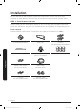
Installation Be sure that you or your installer follow these instructions closely so that the new dishwasher works properly and that you are not at risk of injury when washing dishes. STEP 1 Check the parts and tools Before starting on the installation, prepare all the necessary tools and parts required to install the dishwasher. This will save installation time and simplify the installation process. Parts required Provided with the dishwasher. Check when you unbox the dishwasher in STEP 5.
Not provided Power cable Twist on wire connector Strain relief Electrical tape & Standard duct tape Hot water supply line 90° Fitting (3/4") Tube fittings Air gap Rubber connector NOTE Installation For the hot water supply line – We strongly recommend using 3/8" minimum O.D. copper tubing with a compression fitting or a flexible stainless steel braided hot water supply line. [Warning: Do not use plastic tubing. Plastic tubing can deteriorate over time and cause a leak inside the tube fitting.
Installation Tools required Installation Electric drill Safety glasses Gloves Flashlight Adjustable wrench Wire stripper Pliers Nipper Tape measure Pencil Phillips screwdriver Flat screwdriver Tubing cutter Cutting knife Hole saw Level Torx t20 Hex L-wrench 8 English DW7000B_DW80B7070_AA_DD68-00242A-00_EN.
NOTE New installation If the dishwasher is a new installation, most of the installation work must be done before the dishwasher is moved into place. Replacement If the dishwasher is replacing an old dishwasher, you must check the exising dishwasher connections for compatibility with the new dishwasher. Replace the existing connections as necessary.
Installation If this is a new installation, follow these steps: 1. Using a 21/2 inch hole saw, cut a hole into the side of the cabinet that holds the sink as shown in Figure 1-1 below. 2. If the base inside the sink cabinet is raised above the kitchen floor and is higher than the connections on the dishwasher, make a hole in the base inside the cabinet and in the cabinet side as shown in Figure 1-2. NOTE Depending on where your electrical outlet is, you may need to cut a hole in the opposite cabinet side.
Product dimensions Front view DW80B7070**, DW80B6060** DW80B7071**, DW80B6061** 237/8" (605 mm) 237/8" (605 mm) 33⅞-35" (860-890 mm) 33⅞-35" (860-890 mm) Junction box Junction box Side view Installation DW80B7070**, DW80B6060** DW80B7071**, DW80B6061** 275/16" (693 mm) 21/2" (60 mm) 5 3 / 4 " (140 mm) 41/5" (107 mm) 21/2" (60 mm) 23/4" (70 mm) 201/2" (520 mm) 25" (636 mm) 201/2" (520 mm) 25" (636 mm) You must arrange the water supply line, power cable and drain hose in the space behind th
Installation Cabinet dimensions NOTE 24" (610 mm) minimum 34⅛-35⅓" (867-897 mm) 24" (610 mm) minimum This dishwasher is designed to be enclosed on the top and on both sides by a standard residential kitchen cabinet unit. The installation cabinet must be clean and free of any obstructions. The cabinet must be at least 24 inches wide, 24 inches deep, and 341/8 inches high.
STEP 3 Check water supply requirements and cautions • • The hot water supply line pressure must be between 20~120 psi (140~830 kPa). Adjust the water heater to deliver water between 120 °F (49 °C)~149 °F (65 °C). - - The dishwasher must be connected to a hot water supply between 120 °F (49 °C)~149 °F (65 °C). This temperature range provides the best washing result and shortest cycle time. Temperature should not exceed 149 °F (65 °C) to prevent damage to dishes.
Installation STEP 4 Check the electrical requirements and cautions The electrical requirements for the dishwasher are as follows: • • • In the United States, install in accordance with the National Electric Code/State and Municipal codes and/or local codes. In Canada, install in accordance with the Canadian Electric Code C22.1-latest edition/ Provincial and Municipal codes and/or local codes. For cable direct connections.
STEP 5 Unpacking and inspecting the dishwasher Unpack the dishwasher in an open area free of obstruction both around the packaging and overhead. We recommend that you retain all of the packing materials until the dishwasher is fully installed and operational to ensure you have removed all the product’s components from the packing materials prior to disposal. Unpacking 1. Position the carton right-side-up with top arrows pointing upwards. 2. Unbuckle or cut the straps securing the packaging. 3.
Installation Inspecting Mechanical 1. Check the plastic base assembly to ensure that it is intact 2. Check the dishwasher’s feet to ensure they are in place and can be adjusted so you can level and secure the dishwasher. 3. Check all the visible components on the bottom of the dishwasher to ensure they are intact and secure. 4. Check the door latch, the operation of the hinges, and confirm the door is properly secured to the dishwasher. Plumbing 1.
STEP 6 Mounting the custom panel 1. Open the door and fit the custom panel in the front bottom of the door. Make sure that the ribs of the panel fit into the corresponding holes (totaling 6) of the door. Installation 2. While holding the door and the custom panel with both hands, press the panel evenly from bottom to top to lock into the dishwasher. English 17 DW7000B_DW80B7070_AA_DD68-00242A-00_EN.
Installation 3. When both sides of the panel lock into place, press the top center of the custom panel to secure it to the top of the door. NOTE • • Make sure that the custom panel fits in the dishwasher properly. If the gap between the dishwasher and the custom panel is below 2 mm, proper installation is done. For 2 mm or more, remove the custom panel and try again. 4. Unpack the caps and screws (two for each) included in the product package. 5. Tighten the screws on either side of the dishwasher.
6. Insert the caps on either side. Make sure the rib of the cap fits in the hole of the dishwasher in the right direction. Installation 7. This is the completion of mounting the custom panel. English 19 DW7000B_DW80B7070_AA_DD68-00242A-00_EN.
Installation STEP 7 Preparing the dishwasher 1. Attach the protective sticker (A). - To prevent damage, put the protective sticker on the bottom of the counter top as shown in the picture. NOTE • • Before putting the protective sticker, clean the counter top as shown in the picture. For information, the length of the protective sticker is 26 inches (660 mm). A Installation 2. Ensure that the circuit breaker and water supply valve are turned off before proceeding with the following steps.
3. Use the provided nut connector to connect the water hose to the dishwasher. Follow these steps: 01 02 03 A B E C D F 01 Disconnect the 90° fitting (A) from the hose (B). 02 Remove the seal (C) and the nut (D) from the 90° fitting. 03 From the provided nut connector, separate the seal (E) and the nut (F), and then assemble them to the 90° fitting as shown in the figure. You must insert the smaller side of the seal. 4. Then, insert the 3/4" 90 degree fitting into the inlet valve (See Figure 4-B).
Installation Figure 4 A A A’ A’ C B Junction box Strain relief 90° fitting CAUTION Do not overtighten the 90° Fitting. (Below 280 lb·in (31.6 N·m)) Installation Doing so may damage the water inlet valve and cause a water leak. 22 English DW7000B_DW80B7070_AA_DD68-00242A-00_EN.
STEP 8 Placing the dishwasher and connecting the hot water supply line 1. Adjust the three leveling legs at the bottom of the dishwasher after measuring the height of the cabinet opening from under the countertop to the floor. (See STEP 9, Leveling the Dishwasher.) 2. Locate the hot water supply line and the power cable. 3. Place the dishwasher so that the hot water supply line is in the left side and the power cable is in the right channel of the base of the dishwasher.
Installation Figure 5 Side gasket Side gasket Junction box 1 inch Drain hose Hot Water Supply Line Power cable Inlet valve built-in hook Hot Water Supply Line /4" (9.5 mm)) 3 Elbow ( Installation CAUTION Do not overtighten the 90° Fitting. Doing so may damage the water inlet valve and cause a water leak. Make sure the dishwasher is positioned to the center. 24 English DW7000B_DW80B7070_AA_DD68-00242A-00_EN.
STEP 9 Leveling the dishwasher 1. Open the door and place the level against the top of the tub on the inside and check if the the dishwasher is level. If it is not level, rotate the leveling legs at the bottom front of the dishwasher until the dishwasher is level. See the first note below for instructions on adusting the height of the front legs. 2. Use the level to check if the dishwasher is level front to back, as shown in the figure to the right.
Installation NOTE • • If the leveling legs are rotated to the left (clockwise), they are loosened and the front of the dishwasher is raised. If they are rotated to the right (counter clockwise), they are tightened and the front of the dishwasher is lowered. You can adjust the leveling legs by a max of 16/32" However, leveling up to the max height is not recommended.
STEP 10 Securing the dishwasher You must secure the dishwasher to the countertop or cabinet side walls for additional stability and safety. To the countertop If the countertop is made of wood or the material will not be damaged by drilling, follow this. 1. Put a large towel into the bottom of the dishwasher(covering the filter) to prevent wood shavings or a dropped screw from falling into the sump. 2. Insert the provided brackets into the top front holes of the dishwasher as shown.
Installation To the sides If the countertop is made of granite, marble, or any other material that can be damaged by drilling, follow this. 1. Put a large towel into the bottom of the dishwasher(covering the filter) to prevent wood shavings or a dropped screw from falling into the sump. 2. Insert the provided brackets into the side front holes of the dishwasher as shown. If the brackets are too long, cut them down using pliers. 3. Pre-drill one hole into both sides of the kitchen cabinet.
STEP 11 Securing 1. Check the parts on the sink to which the drain hose will be connected. 2. There are several ways to insert the drain hose into the drain hose connector of the sink, as shown in the following figures. You must connect the drain hose in accordance with the water pipe installation regulations in your region. Figure 8 Case 1. Without disposal Air gap Drain hose Hose clamp Hose clamp Without disposal With an air gap/without disposal Without an air gap Installation Case 2.
Installation Air gap Drain hose Hose clamp Hose clamp With disposal Disposal with an air gap Without an air gap Knock out plug in garbage disposal before connecting the drain hose. Installation 3. Check the size of the sink’s drain hose connector. If needed, cut the drain hose so its end fits onto the sink connector (5/8 in. or 1 in. - as shown in Figure 9 below).
NOTE To prevent leaks or drainage problems, make sure the drain hose is not damaged, kinked, or twisted. 8. Do not cut the ribbed area of the drain hose to fit the size. When arranging the drain hose, take caution not to contact on sharp edges of the cabinet or under-sink. CAUTION • • • Be careful when cutting off the end of the drain hose as there is a risk of injury. Clean around the sink’s drain connection so that it does not damage the hose.
Installation Figure 9 1 in. (25 mm) /8 in. (16 mm) 5 /8 in. (22 mm) 7 If necessary, cut off the dotted line of the drain hose to fit the size. Figure 10 Sink Min. 10 in. (254 mm) Dishwasher To prevent backflow for models without the air gap, secure the drain hose to the side wall of the kitchen cabinet using cable ties or other fixtures. Make sure the drain hose is high at least 10 inches from the sink connector. Installation Drain hose 32 English DW7000B_DW80B7070_AA_DD68-00242A-00_EN.
STEP 12 Wiring connections 1. Before connecting the power cable to the dishwasher, make sure the circuit breaker is off. 2. In the junction box located at the front bottom right of the dishwasher, find the three power wires from the dishwasher including the grounding line. 3. Pass the power cable through the strain relief, and then into the junction box (Figure 11). 4. Connect the black wire of the dishwasher to the black wire of the power cable by insertng both into a wire nut.
Installation Figure 12 WARNING • Electrical Shock Hazard To avoid electrical shock, do not work on an energized circuit. Doing so could result in serious injury or death. Only qualified electricians should perform electrical work. Do not attempt any work on the dishwasher electric supply circuit until you are certain the circuit is de-energized. • Fire Hazard To avoid a fire hazard, make sure electrical work is properly installed. Only qualified electricians should perform electrical work.
STEP 13 Completing the installation 1. Open the door and remove all foam, paper packaging, and unnecessary parts. 2. Turn on the circuit breaker you turned off before you began the installation. 3. Open the water supply valve to supply water to the dishwasher. 4. Turn on the dishwasher, and then select and run a cycle. CAUTION Make sure to check for water leakage on both ends of the water supply line and drain hose connector. 5. Check if the dishwasher turns on properly and check also if there is any leak.
Installation 10. If the “LC” information code continues to appear on the window panel, contact a local service center. 11. Finally, attach the kick plate to the bottom of the dishwasher. While keeping the rubber skirt of the door taut, push the kick plate from the front of the rubber skirt inward underneath the door of the dishwasher. Make sure the gaskets of the kick plate are flush with the floor and side walls. Then, tighten the screws to fix the plate.
Specifications Power supply 120 V, 15 A, 60 Hz AC Water pressure 20~120 psi (140 ~ 830 kPa) 237/8 x 25 x 337/8 in. (605 x 636 x 860 mm) Dimensions (DW80B7070AP / DW80B7070U*/ DW80B6060U*) (Width × Depth × Height) 2313/16 x 2631/32 x 337/8 in. (605 x 685 x 860 mm) (DW80B7071U* / DW80B6061U*) Minimum inlet water temperature 120 °F (49 °C) NOTE Specifications are subject to change without notice for quality improvement purposes.
Memo DW7000B_DW80B7070_AA_DD68-00242A-00_EN.
Memo DW7000B_DW80B7070_AA_DD68-00242A-00_EN.
DD68-00242A-00 DW7000B_DW80B7070_AA_DD68-00242A-00_EN.