LED TV Installation manual imagine the possibilities Thank you for purchasing this Samsung product. To receive more complete service, please register your product at www.samsung.com/register Model [HG690_ZA]Install_Guide_00ENG.indd 1 Serial No.
Figures and illustrations in this User Manual are provided for reference only and may differ from actual product appearance. Product design and specifications may be changed without notice. Introduction This TV has functionality that lets it interact with a set-back box (SBB/STB) and with other TVs in a computer-controlled system for hotels and other hospitality businesses. Interactive : When the TV is powered-up initially, it sends a command to identify the connected SBB/STB.
Contents Introduction............................................................................................................................................................... 2 Operational Modes.................................................................................................................................................... 2 Still image warning..............................................................................................................................................
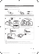
Accessories ✎✎Please make sure the following items are included with your LED TV. If any items are missing, contact your dealer. ✎✎The items’ color and shape may vary, depending on the model. ✎✎The parts for the stand are listed under Stand Components on the following page.
Installing the LED TV Stand The 32” and larger LED TVs have swivel stands. You can set these stands so that the TVs swivel 20 degrees left and right. 60 degrees left and right, or 90 degrees left and right. See page 7. Components When installing the stand, use the provided components and parts.
¦¦ Hotel Mount Kit Bolt + Nut Short Bolt (2EA) Long Bolt (2EA) Nut (2EA) Washer (2EA) Top Bottom 6 Affix the stand to a flat surface such as a dresser top, desk top, or entertainment center as shown. English [HG690_ZA]Install_Guide_00ENG.
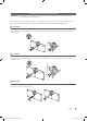
Assembling the swivel (32 inch TVs or larger) ]] WARNING: If you configure the TV to swivel, you must attach it securely to the floor, a desk, a dresser top, etc. as described in the installation instructions. The 32” and larger LED TVs have swivel stands. You can configure these stands so that the TVs swivel 20 degrees left and right, 60 degrees left and right, or 90 degrees left and right using the BRACKET HOLDER SWIVEL.
Using the TV's Controller ✎✎The color and shape of the TV Controller may vary depending on the model. ✎✎The TV's Controller, a small joy stick like button on the bottom right side of the TV, lets you control the TV without the remote control. Open Smart Hub. Open the menu. m Select a source. R P Turn off the TV. TV Controller The control stick is located at the lower-left corner on the back of the TV.
The Connection Panel 0 9 HDMI IN 4 (ARC) 8 7 COMPONENT / AV IN 6 B 1 - SIDE - VIDEIO DVI AUDIO IN DIGITAL AUDIO OUT (OPTICAL) ! 2 (HDD 1.0A) HDMI IN 3 1 3 AUDIO OUT VARIABLE AUDIO OUT AUDIO 4 VOL-CTRL HDMI IN 2 HDMI IN 1 (DVI) EX-LINK @ 5 6 ✎✎Whenever you connect an external device to your TV, make sure that power on the TV and the device is turned off. ✎✎When connecting an external device, match the color of the connection terminal to the cable.
7 EX-LINK: Connect this jack to the jack on the optional RJP (Remote Jack Pack). This will allow you to connect external devices (Camcoder, PC, DVD players etc.) easily. 8 DIGITAL AUDIO OUT (OPTICAL): Connects to a Digital Audio component. 9 DATA –– Used to support data communication between the TV and the SBB or STB. –– Connects using RJ-12 TV type plugs. 0 LAN: Connect to a wired LAN using CAT 6 or CAT 7 cable. ! USB (HDD/1.0A) / CLONING –– Connector for software upgrades and Media Play, etc.
The Remote Control ✎✎This remote control has Braille points on the Power, Channel, and Volume buttons and can be used by visually impaired customers. Display and select the available video sources. Turns the TV on and off. Press to directly access channels. Press to select additional digital channels being broadcast by the same station. For example, to select channel ‘54-3’, press ‘54’, then press '-' and ‘3’. Adjust the volume. Return to the previous channel. Cut off the sound temporarily.
Installing batteries (Battery size: AAA) Match the polarity of the batteries to the symbols in the battery compartment. X Y Z After you have installed the batteries, use a screwdriver to screw in the screw that holds the battery cover closed. ✎✎ NOTE •• Use the remote control within 23~33 feet of the TV. •• Bright light may affect the performance of the remote control. Avoid using near fluorescent lights or neon signs. •• The color and shape of the remote may vary depending on the model.
This TV supports the IEEE 802.11a/b/g and n communication protocols. Samsung recommends using IEEE 802.11n. When you play video over a network connection, the video may not play smoothly. Most wireless network systems incorporate a security system that requires devices that access the network through an access point or AP (typically a wireless IP Sharer - router or modem) to transmit an encrypted security code called an access key.
Connecting the TV to an SBB or STB TV Rear Panel ETH MODEM Data Cable HDMI IN 4 (ARC) COMPONENT / AV IN B VIDEIO DVI AUDIO IN AUDIO OUT VOL-CTRL EX-LINK AUDIO VARIABLE AUDIO OUT DIGITAL AUDIO OUT (OPTICAL) 1. Connect the DATA jack of the TV to the ETH MODEM jack of the STB (SBB) with the Data cable. ✎✎ Data cables are polarized. Make sure you attach the end marked TV Side to the TV and the end marked STB Side to the STB. Also make sure you use the correct data cable for your vendor.
¦¦ List of Vendors and Compatible Data Cables Supplied with the TV yy Confirm you are using the correct data cable for your vendor. Refer to the code label on the data cables. Confirm the code on the Code Label Note the labeled end. Note the labeled end. Vendor Cable code OCC BN39-00865B NXTV BN39-01011B nStreams BN39-01110A MTI BN39-01011C Pin assign Remark Provided LodgeNet MTI Provided English [HG690_ZA]Install_Guide_00ENG.
¦¦ Connecting the Audio Output to an Audio Amplifier TV Rear Panel HDMI IN 4 (ARC) COMPONENT / AV IN B V VIDEIO DVI AUDIO IN AUDIO OUT VOL-CTRL EX-LINK AUDIO IN Audio Amplifier AUDIO VARIABLE AUDIO OUT DIGITAL AUDIO OUT (OPTICAL) 1 Stereo cable 1. Connect the AUDIO OUT port of the TV to the Audio In port of an audio amplifier with a stereo cable. 16 English [HG690_ZA]Install_Guide_00ENG.
Connecting the Bathroom Speakers You can connect the Bathroom Speakers in the following manner. ¦¦ Connecting through the Variable Output (available without an external amplifier) TV Rear Panel HDMI IN 4 (ARC) COMPONENT / AV IN B VIDEIO DVI AUDIO IN AUDIO OUT DIGITAL AUDIO OUT (OPTICAL) EX-LINK 1 VOL+ VOL- AUDIO VARIABLE AUDIO OUT VOL-CTRL Volume Control Box 2 Speaker 1. Connect the VARIABLE AUDIO OUT port of the TV to the Bathroom Wall Speakers of the hotel. Speaker + Speaker - N/C 2.
Connecting the RJP (Remote Jack Pack) Connect the input jacks on the TV to the RJP. The RJP lets guests connect audio and video sources to the TV. RJP Rear USB HDMI 4 RS-232 Data Cable S-VIDEO RCA AUDIO/PC RS/232 TV Rear Panel HDMI IN 4 (ARC) COMPONENT / AV IN B VIDEIO DVI AUDIO IN DIGITAL AUDIO OUT (OPTICAL) ((HDD 1.0A)) 1 D-sub / PC Audio cable HDMI IN 3 HDMI IN 2 AUDIO OUT VARIABLE AUDIO OUT VOL-CTRL HDMI IN 1 ( ) (DVI) AUDIO 2 Video / Audio Cable EX-LINK EK-LINK 3 HDMI cable 1.
yy RJP (Remote Jack Pack): RJP stands for Remote Jack Pack. The RJP is a hardware module that has different Audio Video inputs (A/V, Audio, PC and HDMI) and corresponding outputs. The corresponding outputs are connected from the RJP to the TV. The RJP communicates with the TV via RS232. A Hot Plug & Play function allows hotel guests to connect an external source to the RJP. The RJP communicates with the TV by sending messages regarding Active/Inactive sources.
Setting the Hotel Option Data To let you control how the TV functions when in Hotel mode, the TV has two Hotel mode menus, the Stand-alone mode menu and the Interactive mode menu. The menu items that differ between the menus are listed below.
¦¦ Menu Items To Enter this menu: Press the MUTE → 1 → 1 → 9 → ENTER buttons in order. To exit from this menu : Power Off (or Power Off and unplug if you have changed SI Vendor), and then turn on again. Any changes you made are saved.
Menu Music Mode Item initial Value Description Music Mode AV OFF Allows music output from an mp3/audio player connected to an AV Input Source on the TV. When on, you can hear sound from the player through the TV whether there is a video signal or not. Also mutes the video so the TV does not display a picture when a guest is playing music. The TV's backlight, however, remains on. Music Mode Comp OFF To get music output from an mp3/audio player through a Component Input Source.
Menu Item initial Value Welcome Message OFF Edit Welcome Message Hospitality Logo Edit the Welcome Message. OFF Logo/ Message Turns the Hospitality logo feature on/off. Select from Off, BMP, AVI, or Both. When you select BMP, AVI, or Both, you select the file to use and turn the logo feature on. The Logo is shown during the initial turn on for the amount of time set in "Logo Display Time" Hospitality Logo DL ... Downloads the Hospitality logo.
Menu Item initial Value Widget Mode ON Solution Type Vender Server Server URL Setting Service IPTV Mode Select type of solution (Vender Server/ SINC Server). Set server URL. License Server IP Setting Widget Description Widget Mode ON/OFF. Set server IP. ... IPTV mode On/Off. Virtual Standby OFF Virtual Standby mode On/Off. When Virtual Standby is On, TV power consumption will be 9.5W to 17.4W (Depending on ithe size of the TV screen). External Source Browser ON Source Menu On/Off.
¦¦ Welcome Message The Welcome Message feature displays a custom message on the TV every time it is turned on. –– Welcome message settings are in the Hotel Option Menu. –– Set Welcome Message to ON to display the message when the TV is powered on. Welcome Message OFF Edit Welcome Message Hospitality Logo OFF Hospitality Logo DL ... Logo Display Time ... –– You can make the Welcome Message up to 25 characters long and edit it in the Hotel Service menu.
¦¦ Hospitality Logo The Hospitality Logo function displays the Hotel's picture image when the TV is powered on. –– Hospitality Logo settings are the Hotel mode menus. –– The Logo Download and Logo Display Menu items are enabled when you turn the Hospitality Logo option on. –– If there is a logo image stored in memory and the Hospitality Logo option is on, the Hospitality logo is displayed when the TV is turned on.
¦¦ USB Cloning The USB Cloning function lets you download user-configured settings (Picture, Sound, Input, Channel, Setup, and Hotel Setup) from one TV to a USB device, and then upload these settings from the USB device to other TV sets. This lets you create a standard array of settings and distribute that standard array to all the TVs in your facility. yy Cloning from TV to USB: Copies stored menu settings from a TV to a USB device. 1. Insert a USB drive into the USB port on the rear of the TV. 2.
yy Settings Cloned in the Hotel Menu Menu Item Hospitality Mode SI Vendor Power On Channel EN Power On Channel Channel Type Power On Volume EN Power On Volume Min Volume Max Volume Power On Source Power On Option Channel Setup Channel Editor Channel Bank Editor Channel Bank Service Level Mixed Channel Map Dynamic SI Channel Rescan Message Pan Euro MHEG Channel Auto Store Mychannel En Genre Editor Picture Menu Lock Menu Display Channel Menu Display Panel Button Lock Mute On CC Subtitle Auto On SW Clock Local
Menu Item Hospitality Logo Hospitality Logo DL Logo Display Time Clone TV to USB Clone USB to TV Setting Auto Initialize SIRCH Update Time SIRCH Update Immediate Manual SIRCH SIRCH Channel SIRCH Version SIRCH Group ID REACH IPG Room Type CAS PI AES Data Self Diagnosis PI AES Log View PI AES Log SW Upgrade Service Pattern ATV Cable AGC Gain DTV OpenCable AGC Gain TV Reset Cloning Support Applicable Region Yes N/A Yes N/A N/A Yes Yes Yes N/A Yes N/A No Yes No Yes N/A N/A Yes N/A N/A Yes Yes Yes N/A All Al
¦¦ Multi Code Remocon A Multi Code Remocon is a special remote which is designed to control multiple TV. This is useful where there is more than one TV in a location. You can control up to 10 TVs, each with a different ID code, with one remote. ID numbers are displayed on each TV's OSD. The Initial ID code for each TV is “0”. –– You can set and reset the ID code in Analog TV mode or PC mode. (Not available in DTV mode.) –– You can set the ID code to any digit from 0 to 9.
¦¦ Setting Auto Initialize When you clone settings from one TV to another, you clone both the guest side menu and hotel side menu settings: Picture, Sound, Input, Channel, Setup, and Hotel Setup. This lets you set nearly all of the menu values on your hospitality TVs to the same, standard settings. If you allow guests access to the guest side menus, for example the Picture menu, they can change the settings in those menus so they are no longer standard.
¦ Hotel Plug & Play The Hotel Plug & Play function, which automatically performs the Hotel mode selection, Country Setup, Clock Setup, and Picture Mode Setup, runs once, when power is first turned ON. Setup also runs automatically after you have executed a Service Reset. y UI Scenario Local Set Local Set If you select Change Change Local Set if Located in North America Latin America and Europe. In other regions, Please press SKIP button move to the next step.
yy Hotel Plug & Play OSD –– Initially highlighted: Interactive –– If you select the Standalone Only button, the Standalone hotel mode is set by default and the “Standalone mode is set” OSD appears for 3 seconds. –– TV enters into RF mode automatically after displaying the “Standalone mode is set” OSD for 3 seconds. –– If you select the Interactive mode, the Interactive Setup Menu is displayed. Press the power off key to exit from the Interactive menu.
3. Press the ▲ or ▼ button to select SW Upgrade, and then press the ENTER button. The message "Scanning for USB. This may take more than 1min." is displayed. 4. The message "Upgrade version XXXX to version XXXX? The system will be reset after upgrade." is displayed. Press the ◄ or ► to select the OK, and then press the ENTER button. Please be careful to not disconnect the power or remove the USB drive while upgrades are being applied.
¦¦ Channel Bank Editor (Smoovie TV Only) The Channel Bank Editor in conjunction with the SMOOVIE remote lets you control the channels guests have access to. The Channel Bank Editor provides three Banks of channels and lets you select which channels will be available from each bank. SMOOVIE remotes have installable Bank Cards which correspond to the channel banks in the Channel Bank Editor. The remotes only allow access to channels in the channel bank that correspond to the installed card.
Smoovie Set Up Sequence Smoovie TV Setup (Air/ Cable ) Only Air or Cable used Only Air or Cable used If the TV starts with Hotel Plug&Play If Hotel Plug&Play already done 1 Do a complete P&P (including Air or Cable auto tune) Enter the Hotel menu 2 After P&P, the TV displays the Hotel menu Select the channel type - ATV or ADTV for Air - CATV or CDTV for cable 3 Select the channel type - ATV or ADTV for Air - CATV or CDTV for cable Select Smoovie TV in the Hotel menu 4 Select Smoovie TV in the
The picture below shows a sample Channel Editor screen. yy a Indicates an analog channel. yy Channels without an a are digital channels. yy The guide at the bottom of the Channel Editor menu displays the remote buttons you need to press to apply Channel Editor functions. 1 Using the remote's up or down arrow key, highlight the channel that you want edit. –– To edit more than one channel, move the highlight to a channel, and then press the ENTERE key.
When you press the TOOLS button, the following menu is available. Edit Channel Number Use Edit Channel Number to change the channel number of a channel you select. To change a channel number, follow these steps: 1. Select a channel on the Channel Edit screen. Channel 2. Press the Tools button on your remote. TOOLS aChannel 10 Rename 3. Select Edit Channel Number in the Tools menu. Air 10-1 CW CW DTV Edit Channel Number a 11 HBO Information Air 11-1 HBO DTV 4.
The external sources of this TV are displayed in the last page of the Channel Editor menu as shown in the example below. In the example, there are two external sources connected to the TV, HDMI2(DVI) and AV. –– You can assign a new analog channel to an external source by selecting the source on the last page, pressing the Tools button, selecting Edit Channel Number, and then using the up or down arrow button on the remote to select the channel number of the analog channel.
Installing the Wall Mount Preparing befor installing Wall-Mount (for 46", 50" models) To install a wall-mount from another manufacturer, user the Holder-Ring. ✎✎The Product shape may differ depending on the model. Installing the Wall Mount Kit The wall mount kit (sold separately) allows you to mount the TV on a wall. For detailed information on installing the wall mount, see the instructions provided with the wall mount. Contact a technician for assistance when installing the wall mount bracket.
Wall Mount Kit Specifications (VESA) ✎✎The wall mount kit is not supplied, but sold separately. Install your wall mount on a solid wall perpendicular to the floor. If you are attaching the wall mount to building materials other than plaster board, contact your nearest dealer. If installed on a ceiling or slanted wall, the TV may fall and cause severe personal injury. ✎✎NOTE xx Standard dimensions for wall mount kits are shown in the table below.
Anti-theft Kensington Lock The Kensington Lock is a device you can use to physically fix a TV to a location when you use it in a public place. The appearance and locking method may differ from the illustration at right, depending on the manufacturer. Refer to the manual provided with the Kensington Lock for additional information on proper use. 1 The Kensington Lock is not supplied by Samsung. ✎✎Please find the “K” icon on the rear of the TV. A Kensington slot is beside the “K” icon.
Specifications Display Resolution 1920 x 1080 Environmental Considerations Operating Temperature Operating Humidity Storage Temperature Storage Humidity 50°F to 104°F (10°C to 40°C) 10% to 80%, non-condensing -4°F to 113°F (-20°C to 45°C) 5% to 95%, non-condensing Stand Swivel (Left / Right) -20˚ ~ 20˚ Model Name HG32NB690 HG40NB690 Screen Size (Diagonal) 32" Class (31.5" measured diagonally) 40" Class (40.0" measured diagonally) Sound (Output) Dimensions (WxDxH) Body 10W x 2 29.3 x 1.9 x 17.
Display Resolution When you use your TV as a computer monitor, you can also select one of the standard resolutions listed in the Resolution column. The TV will automatically adjust to the resolution you choose. Mode Resolution Horizontal Frequency (KHz) Vertical Frequency (Hz) Pixel Clock Frequency (MHz) Sync Polarity (H / V) IBM 640 x 350 720 x 400 31.469 31.469 70.086 70.087 25.175 28.322 +/-/+ MAC 640 x 480 832 x 624 1152 x 870 35.000 49.726 68.681 66.667 74.551 75.062 30.240 57.284 100.
Dimensions HG32NB690 / HG40NB690 / HG46NB690 / HG55NB690 ▪▪ Front view / Side view 5 1 3 4 6 2 (Unit: inches) HG32NB690 1 29.0 2 16.5 3 17.2 4 19.8 5 1.9 6 6.2 8.9 HG40NB690 36.5 20.3 21.4 24.0 1.9 HG46NB690 41.7 20.3 24.3 27.0 1.9 8.9 HG55NB690 44.7 20.3 25.9 31.2 1.9 8.9 ▪▪ Jack panel detail / Rear view 3 2 1 4 6 7 5 HG32NB690 1 2 3 4 5 6 7 7.8 7.8 10.5 5.1 4.1 4.8 5.0 HG40NB690 7.8 7.8 14.3 5.1 6.1 6.9 5.0 HG46NB690 15.7 15.7 12.9 5.1 6.
▪▪ Base Stand detail HG32NB690 / HG40NB690 / HG46NB690 / HG55NB690 (Unit: inches) 20.3 8.9 2.6 5.3 R9.5 R3.75 5.9 20.3 8.9 7.5 NOTE: All drawings are not necessarily to scale. Some dimensions are subject to change without prior notice. Refer to the dimensions prior to performing installation of your TV. Not responsible for typographical or printed errors. © 2011 Samsung Electronics America, Inc 46 English [HG690_ZA]Install_Guide_00ENG.
¦¦ Important Warranty Information Regarding Television Format Viewing ✎✎ See the warranty card for more information on warranty terms. Wide screen format LED Displays (16:9, the aspect ratio of the screen width to height) are primarily designed to view wide screen format full-motion video. The images displayed on them should primarily be in the wide screen 16:9 ratio format, or expanded to fill the screen if your model offers this feature and the images are constantly moving.
Contact SAMSUNG WORLDWIDE If you have any questions or comments relating to Samsung products, please contact the SAMSUNG customer care center. Samsung Hospitality Hotline: 866-894-0524 Web site: http://www.samsung.com/us/business HG690-ZA-00 [HG690_ZA]Install_Guide_00ENG.