30X Crisp Image Detection PTZ Dome Camera SPD-3000/2300 User’s Manual SALES NETWORK • SAMSUNG TECHWIN CO., LTD. 145-3, Sangdaewon 1-dong, Jungwon-gu, Seongnam-si, Gyeonggi-do 462-703, Korea TEL : +82-31-740-8137~8139 FAX : +82-31-740-8145 • SAMSUNG OPTO-ELECTRONICS UK, LTD. Samsung House, 1000 Hillswood Drive, Hillswood Business Park Chertsey, Surrey KT16 OPS TEL : +44-1932-45-5308 FAX : +44-1932-45-5325 www.samsungtechwin.com www.samsungcctv.com • TIANJIN SAMSUNG OPTO-ELECTRONICS CO., LTD.
The lightning flash with an arrowhead symbol, within an equilateral triangle is intended to alert the user to the presence of uninsulated “dangerous voltage” within the product's enclosure that may be of sufficient magnitude to constitute a risk of electric shock to persons. The exclamation point within an equilateral triangle is intended to alert the user to the presence of important operating and maintenance (servicing) instructions in the literature accompanying the appliance.
Features Various Auto Surveillances *Individual Preset Saving Modes 13 camera adjustment functions can be saved independently in each Preset menu to provide optimum images. *Various Protocols Five different makersí protocols are supported: Samsung Techwin, Pelco, Samsung Electronics, Panasonic and Vicon. *PTZ Tracking 4 patterns operated with the joystick can be saved and replayed by users. *AUTO Swing Pan or Tilt is operated in sequence between 2 designated positions.
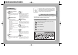
Contents 10 Body Camera Holder Camera Holder Connection Camera Holder Initial Setting 10 Components and Accessories 22 Installation 11 12 13 23 Functional Description 30 OSD Menu Organization Dome Camera User Menu Settings 1. Camera Settings 2. Sequence Setting 3. P/T Setting 4. OSD Setting 5. Alarm Setting 6. Initialization Setting 7.
Precautions Experienced and skilled technicians have to install this product. Unqualified and personal installation may cause fire or electric shock. Contact the dealer for installation. Do not install the product under humid conditions or near flammable or explosive gases. Install the product in a place strong enough to hold it. It may cause failure, electric shock or fire. The product may fall. Do not handle the power plug with wet hands. Do not disassemble or insert foreign objects.
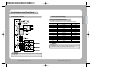
Part Names and Functions Camera Holder ENGLISH Body Function Setup Switch 1. Half/Full 2.3.4.5. RS-485/422 Terminal Setting 6. RS-485/422 Communication 7. Factory setting 8. RS-232 Power Switch Power ON/OFF (Factory Setting: OFF) Controller Connection Input 1. RXD+ 2. RXD- 3. TXD+ 4. TXD- 5. GND 6. TX 7. RX ID Setup Switch Alarm Connection Input 1. IN1 2. IN2 3. GND 7. COM1 8. 1N.C 9. 1N.O 4. IN3 10. COM2 5. IN4 11. 2N.
Part Names and Functions Camera Holder Initial Settings Setting Communications Protocol Use the SW3 of installation bracket to set the communications protocol. SW1 0 1 2 3 4 5 6 7 8 9 10 11 12~F Protocol Samsung Samsung Pelco-D Pelco-D Pelco-D Samsung Elec. Samsung Elec. Samsung Elec.
Part Names and Functions Samsung Pelco Samsung Elec. SVR-430 SVR-440 SVR-1630 SVR-1650 9600,19200 9600,19200 9600,19200 9600,19200 9600 4800, 9600 2400,4800,9600 2400,4800,9600 19,200,38,400 19,200,38,400 19,200,38,400 19,200,38400 Notes • Depending on the DVR firmware version, the Control function may not be supported. Use this function after installation of the final version. Setting Camera ID (Camera Holder) Set the Camera ID using 2 rotary switches (SW1 and SW2).
Part Names and Functions SW2 6 6 6 6 6 6 6 6 6 6 6 6 6 6 6 6 7 7 7 7 7 7 7 7 7 7 7 7 7 7 7 7 8 8 8 8 8 8 8 8 8 8 8 8 8 8 8 8 9 9 SW1 0 1 2 3 4 5 6 7 8 9 A B C D E F 0 1 2 3 4 5 6 7 8 9 A B C D E F 0 1 2 3 4 5 6 7 8 9 A B C D E F 0 1 Remarks SPEED DOME CAMERA Camera ID ID = 146 ID = 147 ID = 148 ID = 149 ID = 150 ID = 151 ID = 152 ID = 153 ID = 154 ID = 155 ID = 156 ID = 157 ID = 158 ID = 159 ID = 160 ID = 161 ID = 162 ID = 163 ID = 164 ID = 165 ID = 166 ID = 167 ID = 168 ID = 169 ID = 170 ID = 171 ID =
Part Names and Functions The following 3 Camera ID’s cannot be used. Notes R-SW2 0 A A R-SW1 0 0 F ENGLISH Camera ID ID = 0 ID = 160 ID = 175 • Factory Settings: Only #2 and #3 are ON. Setting Communication Method (Camera Holder) Setting Transmission Mode (Camera Holder) SW3- #6 Set the transmission mode using the ON/OFF of the Dip Switch 1.
Part Names and Functions CON7- #1 CON7-#2 CON7-#3 CON7-#4 CON7-#5 CON7-#6 CON7-#7 NAME RXD+ RXDTXD+ TXDGND TX RX Purpose Controller Data Line Connection Controller Data Line Connection Controller Data Line Connection Controller Data Line Connection GND For RS-232 Communication For RS-232 Communication Alarm Connection Terminal (Camera Holder) IJP3 - #1 IJP3 - #2 IJP3 - #3 IJP3 - #4 IJP3 - #5 IJP3 - #6 IJP3 - #7 IJP3 - #8 IJP3 - #9 IJP3 - #10 IJP3 - #11 IJP3 - #12 NAME IN1 IN2 GND IN3 IN4 GND COM1 1N.
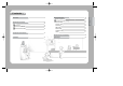
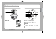
Installation Components and Accessories Adapter AC24V, Peak 2.5A) User s Manual Preparation for Cable To install and use the SPD-3000/2300, the following cables should be used. • Power Adapter Cable The cable connected to the power input terminal of SPD-3000/2300 is shown below with a rated voltage of AC24V 2.5A.
Installation Installation of SPD-3000/2300 2. Next, connect the other end of the connector to the Video Input Terminal of the monitor. Monitor In Terminal Video Out Terminal Monitor 3. Then, connect the Power Adapter Cable. Use a driver (-) to screw one part of the Power Adapter consisting of two lines to the Power Input Terminal of the camera holder. 4. Connect the Power Adapter’s plug to the Power Outlet.
Installation Camera Installation (outdoor Housing) ENGLISH 3) Indoor and Outdoor Housing (STH-330PI, STH-330PO) This housing is used to install the speed dome camera on the indoor or outdoor wall or ceiling. (For the indoor type, the fan and heater are excluded.) 1. Fasten the ceiling mount on the ceiling. 2. Pull outside of the housing the safety wire fastened to the outdoor housing. 4) Wall Type Mount (STB-270PW) This item is used to install the indoor or outdoor housing for speed dome on the wall.
Installation 9. Connect the housing safety wires to the fixture inside the mount installed on the ceiling. 6. Adjust and make the arrows marked on the bottom of the camera an arrow body face each other. 10. Connect the video cable, the controller cable, the power adapter cable and ID cable to the camera holder. 7.
Functional Description P1 Dome camera can be set up on the OSD (On Screen Display) menu displayed on the video monitor by the camera controller. The joystick operations in the OSD menu are as follows. In addition, sending control codes to the camera from the PC can also use the camera functions.
Functional Description P2 Area Setting P/T Setting Area Masking OSD Setting Prop.
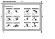
Functional Description FOCUS • Execution of OSD Menu : After checking if the camera is in manual operation mode, press the OSD Menu key or 1+MENU (SCC-16 Model). The following commands are displayed on the monitor screen. • Main Menu The selection key moves up and down. Press the execution key switch on the selected menu to change the setup menu. Press the ESC key to exit the OSD Menu.
Functional Description Camera Setting Focus White Balance Exposure Back Light AGC SSNR Day & Night Others ATW(O) OFF MIDDLE MIDDLE COLOR WB Mode ATW: Balances the colour automatically depending on the source of light from 1,800~10,500K colour temperature. * Indoor[ATW(I)] : Use this mode in the area under the limited colour temperature. * Outdoor[ATW(O)]: Use this mode in the area under the broad colour temperature.
Functional Description Notes • As the accumulated magnification increases, the screen goes bright. But, the after image of the moving object also becomes larger and the optimum Auto Focus function may not work. Camera Setting Focus White Balance Exposure Back Light AGC SSNR Day & Night Others Camera Setting Focus White Balance Exposure Back Light AGC SSNR Day & Night Others ATW(O) OFF MIDDLE MIDDLE COLOR ATW(O) OFF OFF MIDDLE COLOR Select one mode among High, Middle, Low or Off.
Functional Description Camera Setting Focus White Balance Exposure Back Light AGC SSNR Day & Night Others Camera Setting Focus White Balance Exposure Back Light AGC SSNR Day & Night Others ATW(O) OFF MIDDLE MIDDLE AUTO ATW(O) OFF MIDDLE MIDDLE B/W Camera Setting Focus White Balance Exposure Back Light AGC SSNR Day & Night Others ATW(O) OFF MIDDLE MIDDLE COLOR COLOR : Output images are displayed in colour all the time. Burst signal size can be adjusted.
Functional Description 2) Sequence Setting • Sequence Setting Menu Sequence Setting Preset Swing SEQ Group SEQ Tour SEQ PTZ Trace Auto Run Power On Resume OFF Clear : Select the Preset number to delete for clearing. Status : The current Preset number setup is displayed. • Motion Detection Setting Select Motion Detection in the Preset Setting menu and then turn on the mode. Notes • When the illumination is shaking under direct lighting such as a fluorescent lamp, it may cause malfunction of the camera.
Functional Description 6. If you select the Scene Adj. item, such items as Shutter, AGC, SSNR, Sens-Up, White Balance and DIS can be set up differently in every Preset item. Preset Edit PTZ Focus Mode Brightness Iris Back Light Day & Night Motion Det. Scene Adj Scene Adj. Shutter AGC SSNR Sens-Up White Balance DIS [001] 267/051/1X Manual 050 AUTO OFF COLOR OFF [001] --MIDDLE MIDDLE AUTO ATW OFF Notes • In the White Balance setting of the individual Preset Scene Adj.
Functional Description Sequence Setting Preset Swing SEQ Group SEQ Tour SEQ PTZ Trace Auto Run Power On Resume OFF Notes • Press the OSD key to stop the internal memory to continue saving. Tour SEQ Setting Execute Clear Setting : The registered Group Sequence is selected with the joystick and confirmed with the Execution key. If the selected number is not registered, it cannot be input. Press the Execution key in the location with selection mark to finish the setting process.
Functional Description Main Menu Pan Limit : The moving range in the Pan direction can be limited. Main Menu P/T Setting Camera Setting Sequence Setting P/T Setting OSD Setting Alarm Setting Initialize Status Pan Limit Tilt Limit Area Setting Area Masking Prop. P/T Digital Flip ON ON Tilt Limit : Moving range in the tilt direction can be limited. P/T Setting Camera Setting Sequence Setting P/T Setting OSD Setting Alarm Setting Initialize Status Pan Limit Tilt Limit Area Setting Area Masking Prop.
Functional Description Prop. P/T : Pan and Tilt speeds can be changed depending on zoom magnification. Tele will slow down the speed of Pan/Tilt and Wide will increase the Pan/Tilt speed. It will take about 15 seconds for 1 cycle in Tele mode and about 1.5 seconds in the Wide mode. Default setting is ON. Main Menu P/T Setting Camera Setting Sequence Setting P/T Setting OSD Setting Alarm Setting Initialize Status Pan Limit Tilt Limit Area Setting Area Masking Prop.
Functional Description : A maximum of 12 characters consisting of English (or Chinese, Japanese), numbers and special characters can be input for Camera Name. On/Off : The operation of this function is preset. Default setting is On. Preset Number (Default setting is ON.) : Preset numbering is set up.
Functional Description Main Menu OSD Setting Camera Setting Sequence Setting P/T Setting OSD Setting Alarm Setting Initialize Status Camera ID Camera Name Preset Number Preset Name Sequence Status Area Name PTZ Position Language ON ON OFF OFF ON English Language : The OSD can be displayed either in English (default setting) or in Chinese.
Functional Description : If you want to cancel the operating Alarm outputs at once, select the corresponding menu to cancel the operating Alarm. MD Dwell Time : When the Motion Detection function is on, the motion of intruders can be detected. When the motion is detected, the Alarm signal is displayed in the Alarm Output Terminal. For detailed settings of the Motion Detection for each Preset menu, see page 43 and 44.
Product Structure and Installation Installation 243.4 215.7 27.7 ENGLISH Product Structure R75 Ø155 SPEED DOME CAMERA 58 User’s Manual *Other Installations: The outdoor installation accessories, which are sold separately, can be applied in various ways. (See 25 and 26 page for the accessories on sale.
Product Structure and Installation Installation 2 SPEED DOME CAMERA 60 User’s Manual ENGLISH Installation 1 SPEED DOME CAMERA 61 User’s Manual
Specifications SPD-2300 1/4” Colour Vertical Double Density Interline CCD. 410.000pixel TV Accuracy of Horizontal 811(H) X 508(V) Vertical Rotation Valid Pixel 768(H) X 494(V) Vertical Rotation Speed 15.734kHz Vertical Scan Frequency 59.