6900 Hotel 6000 Hotel LED TV installation manual imagine the possibilities Thank you for purchasing this Samsung product. To receive more complete service, please register your product at www.samsung.com/register Model______________ Serial No.______________ UC6900 호주_중아, UC6000 구주 호텔.
Figures and illustrations in this User Manual are provided for reference only and may differ from actual product appearance. Product design and specifications may be changed without notice. Instruction This TV is provided with interactive functionality through a set-back box (SBB/STB) connected to the TV, and with other TVs in a computer controlled system for hotels and other hospitality businesses.
Contents Accessories............................................................................................................................................................... 4 Install the Stand (6900 Hotel)..................................................................................................................................... 5 Install the Stand (6000 Hotel).....................................................................................................................................
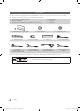
Accessories ✎✎Please make sure the following items are included with your LED TV. If any items are missing, contact your dealer. ✎✎The items’ colour and shapes may vary depending on the models.
Install the Stand (6900 Hotel) Components When installing the stand, use the provided components and parts. A B s s 1 EA 1 EA yy Stand 1 C s s 9EA (M4 X L8) s yy Guide Stand yy Screws 3 B s s s s s A s Front s s s s Top View ss s s s s s s 4EA C s s s s s s s 2 s s s Rear s s 4 s s s s s s s s s s s s s s s ✎✎NOTE xx Make sure to distinguish between the front and back of each component when assembling them.
Install the Stand (6000 Hotel) Component When installing the stand, use the provided components and parts. s s s s Stand (1EA) (A) 5EA (M4 X L12) (B) 5EA (M4 X L8) s Guide Stand (1EA) Screws (10EA) Follow the steps below to connect the TV to the stand. Top view Screws (M4 X L12) s Guide Stand s s s s Front Stand Rear Rear 1. Connect the Guide Stand to the Stand using five screws (M4 X L12) as shown. 2 s s s s s s s s s s s Screws (M4 X L8) 1 2.
0 ! ! * * & & ^ % $ # @ Viewing the Connection Panel ^ % $ # @ UA40C6900VHXZN UA46C6900VHXZN UA55C6900VHXZN 1 1 3 4 3 5 4 5 6 6 7 8 7 9 8 0 9 Power Input 0 ! ! * & ^ % $ # @ * & ^ % $ # @ 1 UA40C6900VHXXY UA46C6900VHXXY UA55C6900VHXXY 1 3 4 3 UA40C6900VHXRD UA46C6900VHXRD UA55C6900VHXRD 5 4 5 6 7 6 7 8 9 8 0 9 0 Power Input ! ! * & ^ $ # @ * & ^ $ # @ English UC6900 호주_중아, UC6000 구주 호텔.
UE40C6000RHXXC UE46C6000RHXXC 1 2 3 4 5 6 7 8 9 0 Power Input ! * & ^ % $ # @ ✎✎Whenever you connect an external device to your TV, make sure that power on the unit is turned1 off. ✎✎When connecting an external device, match the color of the connection terminal to the cable. 1 RJP: This port is an RJP (Remote Jack Pack) communication port that enables connecting different devices to additional module so as to improve device use convenience.
8 AV OUT (Aus, NZ, Singapore) / AUDIO OUT (EU, Central Africa) –– AUDIO OUT: Connects to the audio input jacks on an Amplifier/Home Theater. –– VIDEO OUT: Connect to Video input on an appropriate external display device. (DTV signal is unsupportable. This output is only for Analogue video signal.) 9 VOL-CTRL: Used to control the volume of the Bathroom speaker. Connect the Bathroom Wall Box and the VOLCTRL port. 0 VARIABLE AUDIO OUT: Used for the audio output to the Bathroom speaker.
$ COMPONENT IN –– Connects Component video / audio. –– Connect component video cables (optional) to the component jacks ("PR", "PB", "Y") on the rear of your TV and the other ends to corresponding component video out jacks on the DVD. –– If you wish to connect both the Set-Top Box and DVD, you should connect the Set-Top Box to the DVD and connect the DVD to the component jacks ("PR", "PB", "Y") on your TV.
Viewing the Remote Control ✎✎This is a special remote control for the visually impaired persons and has Braille points on the Power, Channel and Volume buttons. POWER SOURCE Turns the TV on and off. Display and select the available video sources. Selects the HDMI mode directly. HDMI Have direct access to channels. Alternately selects Teletext, Double or Mix. PRE-CH TTX/MIX MUTE Return to the previous channel. Cut off the sound temporarily. Adjust the volume. Change channels.
Connecting the TV with SBB TV Rear Panel Hotel Server STB(Set Top Box) or SBB(Set Back Box) UA40C6900VHXZN UA46C6900VHXZN UA55C6900VHXZN ETH MODEM Data Cable TV Rear Panel Hotel Server STB(Set Top Box) or SBB(Set Back Box) UA40C6900VHXXY UA46C6900VHXXY UA55C6900VHXXY ETH MODEM UA40C6900VHXRD UA46C6900VHXRD UA55C6900VHXRD Data Cable TV Rear Panel Hotel Server STB(Set Top Box) or SBB(Set Back Box) UE40C6000RHXXC UE46C6000RHXXC ETH MODEM ETH MODEM Data Cable 1.
Connecting the Bathroom Speakers You can connect the Bathroom Speakers in the following method. ¦¦ Connecting through the Variable Output (available without an external amplifier) TV Rear Panel Volume Control Box VOL+ 2 VOL- 1 Speaker 1. Connect the VARIABLE AUDIO OUT port of the TV to the Bathroom Wall Speakers of the hotel. Signal wire : Speaker + Shield wire : Speaker - 2. Connect the VOL-CTRL jack of the TV to the Volume Control Box Switch port of the Bathroom Wall of the hotel.
yy Variable Output Port Specifications –– Speaker Wire: Use speaker cable no more than 82 feet (25m) in length. Volume Control Box VOL + 1 3 2 VOL - VOL - UP GND VOL - DOWN ( White 1 ) ( Black /Red 2 ) ( Shield Wire 3 ) ¦¦ Connect through the Fixed Output (available without an external amplifier) Audio Amplifier TV Rear Panel AUDIO IN 1 Stereo cable 1. Connect the AUDIO OUT port of the TV and the Audio In port of the audio amplifier with a stereo cable. 14 English UC6900 호주_중아, UC6000 구주 호텔.
Connecting the MediaHub HD Output of any external source connected to MediaHub HD on hotel desk. MediaHub HD Rear USB HDMI RS/232 TV Rear Panel 1 RS-232 Data Cable 2 HDMI cable 1. Connect the RJP port of the TV and the RS/232 port of the MediaHub HD. 2. Connect the HDMI port of the TV and the HDMI port of the MediaHub HD. yy MediaHub HD –– The MediaHub HD is a hardware module that has different Audio Video inputs (A/V, Audio, PC, HDMI and USB) and corresponding outputs.
Connecting the RJP (Remote Jack Pack) Output of any external source connected to RJP on hotel desk. RJP Rear USB HDMI S-VIDEO RCA AUDIO/PC RS/232 TV Rear Panel 1 2 Video / Audio Cable 3 HDMI cable 4 D-sub / PC Audio cable 1. Connect the RJP port of the TV and the RS/232 port of the RJP. 2. Connect the AV IN [VIDEO]/[L-AUDIO-R] port of the TV to the RCA port of the RJP. 3. Connect the [HDMI] port of the TV and the HDMI port of the RJP. 4.
yy The following table shows the approximate time in seconds to switch from the TV to the input source, based on the priority. ✎✎ Scenario 1: When no inputs are connected. Source To Connect AV PC HDMI 2 Sec 0.7 Sec 3.9 Sec ✎✎ Scenario 2: When two or more inputs are connected and an Input source is disconnected and then reconnected. Source Disconnect To Connect Total AV PC HDMI 4.5 Sec 0.7 Sec 3.9 Sec 2 Sec 0.7 Sec 3.9 Sec 6.5 Sec 1.4 Sec 7.8 Sec ✎✎ E.g.
Setting the Hotel Option Data ¦¦ Stand-alone Mode To Enter: Press the MUTE → 1 → 1 → 9 → ENTER buttons in order. To Exit from this menu : power off and turn on again. No Item initial Value 1 Hotel Mode On 2 SI Vendor Off 3 Power On Channel 1 4 Channel Type ATV Description Hotel mode(Stand alone) on/off Select the SI Vendor TV will switch on to this particular Channel Provides channel Type description for Power On channel selected. i.e.
No Item initial Value Description Selection of the way to update clock data • Auto: Use clock data from server when the TV is in the interactive mode. • Manual: Use clock data from DVB channel or manual clock setting when the TV is in the stand-alone mode. • TTX: manual clock setting (with updating from TTX data) 23 Local time Manual 24 Audio Loop In OFF Audio loop identification or H.
¦¦ Interactive Mode To Enter: Press the INFO → MENU → 0 → 1 → EXIT buttons in order, in normal operation state. To Exit from this menu : Power Off and Turn On again. (Press POWER button with general SAMSUNG remocon) No Item initial Value Description 1 Hotel Mode On 2 SI Vendor Samsung 3 Power On Channel 1 4 Channel Type ATV Provides channel Type description for Power On channel selected. i.e.
No Item initial Value Description 23 Local time Manual Selection of the way to update clock data • Auto: Use clock data from server when the TV is in the interactive mode. • Manual: Use clock data from DVB channel or manual clock setting when the TV is in the stand-alone mode. • TTX: manual clock setting (with updating from TTX data) 24 Audio Loop In OFF Audio loop identification or H.
¦¦ Welcome Message Welcome message is a feature to display custom message on TV, every time TV is turned on by Guest in Hotel room. –– Welcome message settings are placed in Hotel Option Menu. –– Welcome message should be ON in order to display the message on power on.
¦¦ Customer Logo (Hotel Logo) Customer Logo is a function that displays picture image or Video file which represents hotel during power on procedure. –– Customer Logo will be in hotel option menu in both Standalone and Interactive mode. –– Lower menus will be enabled when Customer Logo option is on. –– Customer Logo will be displayed if there is picture image or video file which is already stored in memory and Customer Logo option is on during power on procedure.
¦¦ USB Cloning USB Cloning is a function to download user configured settings (Picture, Sound, Input, Channel, Setup and Hotel Setup) from one TV set and upload the same to other TV sets. All the user-defined settings from the TV (Master Set) can be copied to the USB device. USB Cloning is in hotel option menu in both Standalone and Interactive mode. yy Cloning from TV to USB: It is an operation to copy the stored data from the specific area on the EEPROM from the TV set to the USB device. 1.
¦¦ Hotel Plug & Play Hotel Plug & Play is a function that automatically performs the Hotel mode selection, Country Setup, Clock Setup and Picture mode Setup once. –– Hotel Plug & Play is available only one time when power is first turned ON. –– After setting up first TV and Clone TV to USB –– Next TV only needs to exit Hotel Plug & Play, connect USB, then Clone USB to TV.
yy UI Scenario (Aus, NZ, Singapore) If Standalone Only is selected Hotel Plug & Play Easy Set Up Interactive Standalone Plug & Play Standalone Only mode is set If Interactive is selected If Standalone Plug & Play is selected Interactive Hotel Option Menu Channel Source Select Country. : Australia Press Power OFF to exit. Hotel Plug & Play Hotel Plug & Play Country r Enter Hotel Plug & Play : Digital & Analogue r U After A Previous D Skip U Move Exit Searching the channels.
yy Hotel Plug & Play OSD –– Initial Highlight: Interactive –– If Standalone Only button is selected, the Standalone hotel mode is set by default and “Standalone mode is set” OSD is displayed for 3 seconds. –– TV enters into RF mode automatically after displaying “Standalone mode is set” OSD for 3 seconds. –– When Interactive mode is selected, Interactive Setup Menu is displayed. Press power off button to exit from Interactive menu.
¦¦ Multi Code Remocon Multi Code Remocon is a special transmitter which is designed to control each TVs with one remote. This function is useful where there is more than one TV in one location like hospital Set ID number will be displayed in source osd. It is possible to support up to 10 different remote key transmission for multi code. Initial ID code which each TV has is “0”. –– ID code could be set and reset in Analog TV mode or PC mode. (not available in DTV channel) –– ID code could be from 0 to 9.
¦¦ Mixed Channel Map Mixed Channel Map is a function to mix Air and Cable channels. [ If there are no Cable channels, you can use this item as channel sorting. ] –– Mixed channel Map, Channel Editor and Channel Auto Store are newly placed in Hotel Option Menu. –– Mixed channel Map should be ON in order to mix Air and Cable channels. –– Use Channel Editor to sort the channels as user-desired channel numbers. Hotel Mode ON RJP Priority AV 1 Logo Download ...
1. Rearrange Air and Cable Channels based on User-desired Channel List in ‘Channel Editor’ a. Check the largest channel number from the user-desired channel list. Chnnel No. A A A A Programme Name 1 2 3 4 5 6 7 8 9 BBC1 BBC2 FR1 BOXER FR2 TF1 Disney M6 Canal+ ← Programme 'Canal+' has the largest channel number b. Locate cursor to a programme that you want to put it into the largest channel number. c. Press TOOLS key. d. Move cursor to Edit Channel Number and press ENTERE key.
f. Check the second largest channel number from the user-desired channel list. Chnnel No. Programme Name 1 2 3 4 5 6 7 8 9 A A A A BBC1 BBC2 FR1 BOXER FR2 TF1 Disney M6 Canal+ ← Programme 'M6' has the second largest channel number g. Locate cursor to the other programme that you want to put it into the second largest channel number. h. Press TOOLS key. i. Move cursor to Edit Channel Number and press ENTERE key. 1 BBC1 A 1 2 A 2 A 3 4 A 4 9 900 j.
Assembling the Cables Stand Type 1 1 2 2 3 3 Wall-Mount Type ✎✎Do not pull the cables too hard when arranging them. This may cause damage to the product’s connection terminals. 32 English UC6900 호주_중아, UC6000 구주 호텔.
Installing the Wall Mount Assembling the Blanking Bracket When installing the TV onto a wall, attach the Blanking Bracket as shown. Blanking Bracket Assembling Power-Cord When Installing the TV onto a wall, attach the Power-Cord as shown. 1 2 3 1. Remove the screw shown in the first picture above. 2. Attach the power cord clamp to the power cord. 3. Mount the power cord clamp to the TV, using the removed screw, as shown.
Installing the Wall Mount Kit The wall mount kit (sold separately) allows you to mount the TV on the wall. For detailed information on installing the wall mount, see the instructions provided with the wall mount. Contact a technician for assistance when installing the wall mount bracket. Samsung Electronics is not responsible for any damage to the product or injury to yourself or others if you elect to install the TV on your own.
Securing the TV to the Wall Caution: Pulling, pushing, or climbing on the TV may cause the TV to fall. In particular, ensure your children do not hang over or destabilize the TV; doing so may cause the TV to tip over, causing serious injuries or death. Follow all safety precautions provided on the included Safety Flyer. For added stability, install the anti-fall device for safety purposes, as follows. ¦¦ To Avoid the TV from Falling 1. Put the screws into the clamps and firmly fasten them onto the wall.
Specifications Items TV System Audio out Input Specification Comment PAL, SECAM, DVB-T/C Speaker out 10W x 2 (40" 46") 15W x 2 (55") Variable Audio 4W mono 8 ohm SPK' Audio out 500mVrms Component Y, Pb, Pr, Audio-L/R PC D-sub, Audio-L/R A/V Audio Video Jack EXT Scart Jack (EU, Central Africa Only) HDMI Compatible with the HDMI Specifications Antenna 75 ohm Unbalanced, Din Jack DATA RJ-12 RJP RS232 Data Operating Temperature 10°C ~ 40°C (50°F ~ 104°F) Operating Humidity 10% ~ 8
This page is intentionally left blank. UC6900 호주_중아, UC6000 구주 호텔.
Contact SAMSUNG WORLDWIDE If you have any questions or comments relating to Samsung products, please contact the SAMSUNG customer care center. Country Customer Care Centre AUSTRIA 800-112233 FINLAND 0771-400002 FRANCE 0825-022062 GERMANY 01805-471101 HUNGARY 0640-985985 ITALIA 800-194194 NETHERLANDS 015-2197000 POLAND 0-801-B2BSAM (222726) PORTUGAL 808-B2BSAM SPAIN 0902024-010 UNITED KINGDOM +44 (0) 845 8414141 SOUTH AFRICA U.A.