AVR32416: AVR32 AP7 Linux LCD Panel Customization Features • Hardware - Display connection - Special wirings (color swap) - Bandwidth considerations • Software - Editing the LCD configuration - Adding a LCD driver - Using the low level LCD abstraction layer 32-bit Microcontrollers Application Note 1 Introduction This application note describes all necessary steps to successfully connect a custom LCD display to an AP7 device running the Linux® operating system.
Hardware 2.1 Display interface The typical interface of a display is based on analog and digital inputs. The digital lines are a data bus, pixel clock, vertical and horizontal synchronization signals and a data enable line. The voltage input is generally used for contrast control. The LCD Controller drives all these interface lines. If more inputs are required by the display, it may be managed by GPIOs (power control, AC bias on some STN displays, backlight control, etc.) or other peripheral (SPI,I2C etc.
AVR32416 Name PWR GP[7:0] LCDD[23:0] Description LCD panel Power enable control signal LCD General purpose lines LCD Data Bus output Type Output Output Output 2.1.1 Standard configurations The Controller supports the following interface configurations: 4-bit single scan STN display 4 parallel data lines are used to shift data to successive single horizontal lines one at a time until the entire frame has been shifted and transferred.
Table 2-2 LCD controller data signal multiplexing LCD Data Bus 4-bit STN Single Scan (mono, color) 8-bit STN Single Scan (mono, color) 8-bit STN Dual Scan (mono, color) 16-bit STN Dual Scan (mono, color) 24-bit TFT 16-bit TFT LCDD[23] BLUE7 BLUE4 LCDD[22] BLUE6 BLUE3 LCDD[21] BLUE5 BLUE2 LCDD[20] BLUE4 BLUE1 LCDD[19] BLUE3 BLUE0 LCDD[18] BLUE2 Intensity Bit LCDD[17] BLUE1 LCDD[16] BLUE0 LCDD[15] LCDLP7 GREEN7 GREEN4 LCDD[14] LCDLP6 GREEN6 GREEN3 LCDD[13] LCDLP5 GREEN5
AVR32416 2.1.2.3 Hardware swap for 16-bit resolution In a 16-bit resolution the opposite of the BGR-555.1 format is considered as the RGB565 format. Therefore a hardware swap for a 16-bit resolution needs more considerations especially because here the intensity bit needs to be used appropriately. More information about the frame buffer layout and data ordering can be found in chapter “3.5 Frame buffer”.
Figure 2. 2D Frame Buffer Addressing 2.3 Bandwidth considerations An attached display needs a lot of bandwidth from the expansion bus of the system. This must be considered in the display selection process. The bandwidth needed is calculated by following formula: NeededBandwidth = DispaySize x BitsPerPixel x FrameRate Depending on the applications an operating system is running in parallel enough bandwidth should be available.
AVR32416 2.3.2 16-bit memory example (as on the NGW100) The NGW100 uses a 16bit wide interface to the external memory. Thus the maximum available bandwidth is: AvailableBandwidth = 75 x 16/8 Bytes/s = 150 MB/s While a QVGA display leaves enough room for MPEG4 decoding and other tasks a VGA display may not be used in this constellation. Never the less it is possible to show graphics on the VGA display which do not need to be updated at high frequencies. 3 Software 3.
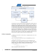
Figure 3-1 Frame buffer and LCD driver software overview The main part is the frame buffer driver with the underlying LCD controller driver and a frame buffer. These parts are necessary components in order to build up a functioning system. Depending on the LCD an extra LCD driver may be needed to do configuring or power up/down through interfaces like SPI or GPIO. A LCD driver can be tied to the frame buffer driver by using a low level LCD abstraction layer.
AVR32416 Graphics support -> Support for frame buffer devices -> AT91/AT32 LCD Controller support These will add the LCD controller driver and the frame buffer driver to the kernel. If one of the LCD low level abstraction layers should be used with the LCD driver they can be activated under Device Drivers -> Graphics support -> Support for frame buffer devices -> Backlight & LCD device support A selection entry for a custom LCD driver should be added here if necessary.
Table 3-1. Frame buffer data ordering 24-bit resolution not packed MSB LSB 31 – 24 Unused 23 – 16 Blue 15 – 8 Green 7-0 Red The packed 24-bit resolution removes the unneeded empty 8-bit which results in a smaller frame buffer. Table 3-2 shows how the data must be placed in the frame buffer in order to be compliant with a packed 24-bit configuration. The second blue component belongs to the next pixel. Table 3-2.
AVR32416 .right_margin = 33, .upper_margin = 10, .lower_margin = 10, .hsync_len = 16, .vsync_len = 1, .sync = 0, .vmode = FB_VMODE_NONINTERLACED, }, }; The fields must be filled out according to the datasheet of the LCD. The pixel clock must be in picoseconds, the horizontal timings in number of pixel clocks and the vertical timings in number of scanlines. Table 3-4.
Figure 3-2 Display timings All timings in the gray area represent the blanking area. For the internal synchronization mechanism, the display may need some dummy data at the beginning and/or end of a line, and at the beginning and/or end of a frame. This is called blanking. The dummy pixels/lines are not part of the frame buffer are therefore managed by the LCD Controller. Some delays must be introduced in vertical and horizontal timings to support it.
AVR32416 .monitor = "LTV350QV", .modedb = ltv350qv_modes, .modedb_len = ARRAY_SIZE(ltv350qv_modes), .hfmin = 14820, .hfmax = 22230, .vfmin = 60, .vfmax = 90, .dclkmax = 30000000, }; The maximum and minimum parameters specified here will make sure that the LCD controller can not be configured with values that do not fit into that range. A configuration value below or above the specification will be set to the lower or the upper limit.
Parameter Description default_bpp Bits per pixel to use. Possible values are 1, 2, 4, 8, 15, 16, 24 and 32. The memory layout for these values is described in the datasheet of the device. For instance 32bit means 3x8bit for the three colors red, green, blue and empty 8bit at the end. default_dmacon Setting ATMEL_LCDC_DMAEN is mandatory in order to enable the LCD controller DMA engine. The ATMEL_LCDC_DMA2DEN will activate the double buffering of the frame buffer.
AVR32416 needed for other things the following function must be edited in the file arch/avr32/mach- at32ap/at32ap700x.c. struct platform_device *__init at32_add_device_lcdc( unsigned int id, struct atmel_lcdfb_info *data, unsigned long fbmem_start, unsigned long fbmem_len ) In this function the pins can be freed by commenting out or removing lines like: select_peripheral(PD(16), PERIPH_A, 0); /* DATA22 */ 3.6.2.
GCCTRL6 = GCCTRL7 = 0 16 osc32k osc0 pll0 cpu hsb pba pclk mck mck mck mck mck usart usart spi_clk twi_pclk pclk pbb pclk pclk hmatrix_clk pclk pclk pclk mci_clk pclk pclk pclk ebi hramc mck hclk hclk hclk hck1 hclk pico lcdc_clk * gclk0 * pll1 sample_clk * gclk1 * gclk2 * gclk3 * gclk4 * osc1 users= 1 users=24 users=23 users=22 users=20 users=10 users= 1 users= 1 users= 1 users= 1 users= 1 users= 1 users= 1 users= 1 users= 1 users= 0 users= 1 users= 6 users= 1 users= 1 users= 1 users= 1 users= 1 users=
AVR32416 LCD controller driver configures the prescaler unit according the configuration it gets from the board setup code or later on from the fbset tool. As previously mentioned can a scaler only divide the clock by 2^n (n=0…). If an exact pixel clock is needed the “lcdc_clk” must be a multiple of 2 or exactly the desired clock rate. A good solution is to use the PLL1 as input for the “lcdc_clk” because it provides the ability to get very close to desired clock rate.
correct view, the LCD Controller and its DMA engine have to be restarted. A possible solution to guarantee access to the external bus interface for the LCD Controller is to enable a priority based arbitration algorithm for this slave. If the LCD Controller gets the highest priority for the slave it is guaranteed that it gets access before all other masters. A major drawback is that all other masters will have a reduced access or even in a worst case no access at all to the slave.
AVR32416 struct device *parent, void *devdata, struct lcd_ops *ops); void lcd_device_unregister(struct lcd_device *ld); Functions that can be implemented in a LCD driver are listed in the struct lcd_ops. 3.7.2 Backlight layer The backlight client provides an easy integration of the backlight control in the frame buffer driver and the LCD driver. Relevant files are include/linux/backlight.h and drivers/video/backlight/backlight.c.
default n help If you have a Samsung LTV350QV LCD panel, say y to include a power control driver for it. The panel starts up in power off state, so you need this driver in order to see any output. The LTV350QV panel is present on all ATSTK1000 boards. For a custom LCD driver a similar entry has to be made in the same file. First a custom configuration name needs to be added to the “config” entry. This name will be referred to from other modules or configuration dependencies.
Disclaimer Headquarters International Atmel Corporation 2325 Orchard Parkway San Jose, CA 95131 USA Tel: 1(408) 441-0311 Fax: 1(408) 487-2600 Atmel Asia Room 1219 Chinachem Golden Plaza 77 Mody Road Tsimshatsui East Kowloon Hong Kong Tel: (852) 2721-9778 Fax: (852) 2722-1369 Atmel Europe Le Krebs 8, Rue Jean-Pierre Timbaud BP 309 78054 Saint-Quentin-enYvelines Cedex France Tel: (33) 1-30-60-70-00 Fax: (33) 1-30-60-71-11 Atmel Japan 9F, Tonetsu Shinkawa Bldg.