E_cov.
1E_cov.fm Page 2 Wednesday, January 23, 2002 9:02 AM For Better Display 1. Adjust computer resolution and screen injection rate (refresh rate) in control panel of computer as described below to enjoy the best quality of picture. You can have an uneven quality of picture in the screen if the best quality of picture is not provided in TFT-LCD. • Resolution: 15” 1024 x 768 • Vertical frequency (refresh rate): 60 Hz 17” 1280 x 1024 2.
English 1 Français Safety Instructions. . . . . . . . . . . . . . . . . . . . . . . . . . . . . . . . . . . . . . . . . . . . . . . . . . . . . . . . . . . 2 Unpacking Your TV/Monitor . . . . . . . . . . . . . . . . . . . . . . . . . . . . . . . . . . . . . . . . . . . . . . . . . . . 3 Setting up Your LCD TV/Monitor . . . . . . . . . . . . . . . . . . . . . . . . . . . . . . . . . . . . . . . . . . . . . . 4 Setting up an Ergonomic Workstation . . . . . . . . . . . . . . . . . . . . . . . . . . . . . .
3E_LW-15E23C/17E24Csaf.fm Page 2 Monday, October 8, 2001 2:52 PM Safety Instructions 1 2 3 4 5 6 7 8 9 10 11 12 13 14 Before connecting the AC power cord to the DC adapter outlet, make sure the voltage designation of the DC adapter corresponds to the local electrical supply. Never insert anything metallic into the cabinet openings of the liquid crystal display (LCD) TV/Monitor; doing so may create the danger of electric shock. To avoid electric shock, never touch the inside of the LCD TV/Monitor.
4E_body3p.fm Page 3 Wednesday, December 19, 2001 4:09 PM Unpacking Your TV/Monitor Please make sure the following items are included with your TV/Monitor. If any items are missing, contact your dealer.
4E_body3p.fm Page 4 Wednesday, December 19, 2001 4:09 PM Setting up Your LCD TV/Monitor Setting up an Ergonomic Workstation Consider the advice given below before you install your TV/Monitor. TV/Monitor location Choose a position that exposes your TV/Monitor to the least reflection from lights or windows, usually at a right angle to any window. Workstation height Place your LCD TV/Monitor so that the top of the screen is slightly below your eye level when you are comfortably seated.
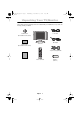
4E_body3p.fm Page 5 Wednesday, December 19, 2001 4:09 PM Setting up Your LCD TV/Monitor Connecting Your LCD TV/Monitor DC POWER VIDEO AUDIO(ST) SCART E VID O S -VIDE O TV or VCR Figure 2. Cable connections 1. Connecting Computer ( ➀ ➁ ➂ ) A. Connect the power cord to the DC Adaptor and connect the adaptor jack to the DC 14V power connector on the back of the TV/Monitor. B. Connect the 15-pin D-SUB of the video signal cable to the PC video connector on the back of the TV/Monitor. C.
4E_body3p.fm Page 6 Wednesday, December 19, 2001 4:09 PM Setting up Your LCD TV/Monitor Plug and Play The adoption of the new VESA® Plug and Play solution eliminates complicated and time consuming setup. It allows you to install your TV/Monitor in a Plug and Play compatible system without the usual hassles and confusion. Your PC system can easily identify and configure itself for use with your display.
4E_body3p.fm Page 7 Wednesday, December 19, 2001 4:09 PM Setting up Your LCD TV/Monitor If the TV/Monitor is functioning properly, you will see a white box with a large blue oval Samsung logo and an error message “Check Signal Cable.” in red color. Check Signal Cable Figure 4. TV/Monitor self-test screen This box also appears during normal operation if the video cable becomes disconnected or damaged.
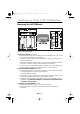
4E_body3p.fm Page 8 Wednesday, December 19, 2001 4:09 PM Adjusting Your LCD TV/Monitor User Controls Your LCD TV/Monitor allows you to easily adjust the characteristics of the image being displayed. All of these adjustments are made using the control buttons on the top of the TV/Monitor. While you use these buttons to adjust the controls, an OSD shows you their numeric values as they change. Figure 5. User control locations No. Name 1 PC Description ■ ■ ■ 2 PIP ■ Selects PC source.
4E_body3p.fm Page 9 Wednesday, December 19, 2001 4:09 PM Adjusting Your LCD TV/Monitor No. Name Description ■ 7 VOL ■ ■ 8 EXIT ■ ■ ■ 9 AUTO 10 POWER ■ ■ Moves the selector left or right on the OSD. Increases or decreases the values of the selected function. Increases or decreases the level of audio volume. Exits from menus and sub-menus. Exits from the OSD system. “Auto” allows the TV/Monitor to self-adjust to the incoming video signal.
4E_body3p.fm Page 10 Wednesday, December 19, 2001 4:09 PM Adjusting Your LCD TV/Monitor Direct-Access Features While you are watching full screen TV or in PIP mode Valid only after performing "Channel auto program". When OSD is not on the screen, push the " " or " " button to select program channel number. Program 1 Push the " number. 2 Push the " " button to increase the channel number. " button to decrease channel When OSD is not on the screen, push the " " " button to adjust volume.
4E_body3p.fm Page 11 Wednesday, December 19, 2001 4:09 PM Adjusting Your LCD TV/Monitor On Screen Display (OSD) Accessing the menu system 1 2 3 4 5 With the OSD off, push the MENU button to display the main OSD menu. Use the " " buttons to move from one function to another. As you move from one icon to another, the function name changes to reflect the function or group of functions represented by that icon.
4E_body3p.fm Page 12 Wednesday, December 19, 2001 4:09 PM Adjusting Your LCD TV/Monitor OSD functions and adjustments Function icons Language Function name Setting bar Main menu Tool Tip Press MENU Key Table 1. Screen controls Main Menu Icon Function Descriptions Menus and Sub-menus Language OSD language and appearence can be changed. English Deutsch Español Français Italiano Svenska Português Nederland Position Move the OSD Window to the vertical and horizontal direction.
5E_LW-15E23C/17E24Cbody13p.fm Page 13 Tuesday, November 13, 2001 10:17 AM Adjusting Your LCD TV/Monitor PC functions and adjustments Function icons Contrast Function name - Setting bar Tool Tip Main menu + Press MENU Key Table 1. Screen controls (Continued) Main Menu Icon Function Descriptions Menus and Sub-menus Contrast Brightness Color Control The tone of color can be changed from redish white to bluish white. The individual color components are also user customizable.
5E_LW-15E23C/17E24Cbody13p.fm Page 14 Tuesday, November 13, 2001 10:17 AM Adjusting Your LCD TV/Monitor Table 1. Screen controls (Continued) Main Menu Icon Function Descriptions Menus and Sub-menus Image • Image Lock • Image Size • Image Effect Image Lock Image Lock is used to fine tune and get the best image by removing noises that create unstable images with jitters and shimmers.
5E_LW-15E23C/17E24Cbody13p.fm Page 15 Tuesday, November 13, 2001 10:17 AM Adjusting Your LCD TV/Monitor Table 1. Screen controls (Continued) Main Menu Icon Function Descriptions Menus and Sub-menus Image Size The size of the image being displayed can be handled in several different ways. ■ Expand1 Resize the image to fill the whole screen. (applicable to PC RGB only) ■ Expand2 Expand images keeping the original aspect ratio.
5E_LW-15E23C/17E24Cbody13p.fm Page 16 Tuesday, November 13, 2001 10:17 AM Adjusting Your LCD TV/Monitor Table 1. Screen controls (Continued) Main Menu Icon Function Descriptions Menus and Sub-menus H-position V-position Sound The TV/Monitor has a built-in high fidelity stereo audio amplifier. The audio circuit processes audio signal from various external input sources such as DVD, VCR, TV or PC. ■ Bass Emphasize low frequency audio. ■ Treble Emphasize high frequency audio.
6E_body17p.fm Page 17 Wednesday, December 19, 2001 4:50 PM Adjusting Your LCD TV/Monitor TV/ Video functions and adjustments Function icons Picture Function name Mode Contrast Brightness Sharpness Colour Tint Setting bar Main menu Standard 45 65 57 40 50 Tool Tip Press MENU Key Table 1. Screen controls (Continued) Main Menu Icon Function Descriptions Menus and Sub-menus Picture This funtion is active if you select an input source other than PC.
6E_body17p.fm Page 18 Wednesday, December 19, 2001 4:50 PM Adjusting Your LCD TV/Monitor Table 1. Screen controls (Continued) Main Menu Icon Function Descriptions Menus and Sub-menus Sound The TV/Monitor has a built-in high fidelity stereo audio amplifier. The audio circuit processes audio signal from various external input sources such as DVD, VCR, TV, Scart, or PC. ■ Mode The diverse sound users need. (Standard, Music, Movie, Speech, Custom) ■ Bass Emphasize low frequency audio.
6E_body17p.fm Page 19 Wednesday, December 19, 2001 4:50 PM Adjusting Your LCD TV/Monitor Table 1. Screen controls (Continued) Main Menu Icon Function Descriptions Menus and Sub-menus ■ Name To... Press the... - Select a program or button - Move on the next or previous letter or button ■ Add/ Erase To select the required channel. To add or erase the desired channel by pressing the , or , button. ■ Fine Tune To select the “Fine tune” and press the button.
6E_body17p.fm Page 20 Wednesday, December 19, 2001 4:50 PM Appendix By Remote-Control PC mode On Display setup information Power On/Off TV/Video mode on & Source Change The diverse screen users need Screen pause The diverse sound users need Channel Up/Down Page Up/Down (Teletext mode) Turn on the OSD Select a function Teletext Index (Teletext mode) Volume Up/Down Turn off the OSD Sound mute Numeric keypads for direct channel access.
6E_body17p.fm Page 21 Wednesday, December 19, 2001 4:50 PM Appendix ■ Features that can only be accessed via remote controller Display Shows a selected video source, audio soure, current channel number sound mode and the state of audio mute on the upper right corner of the screen. P2 NICAM DUAL/I/II BBC Stereo You can set the audio mode by using this button.
6E_body17p.fm Page 22 Wednesday, December 19, 2001 4:50 PM Appendix ■ TELETEXT (TTX) MODE ■ TTX ON (MIX ■ ) This key is used to toggle TTX MODE and TTX MIX MODE. When TTX KEY is converted to TV MODE, TV MODE is changed to NORMAL SIZE TTX MODE. While changing to FULL TTX MODE, OSD vanishes.
6E_body17p.fm Page 23 Wednesday, December 19, 2001 4:50 PM Appendix HOLD SIZE REVEAL / ■ The MULTIPLE PAGE display changes after a certain time passes. The display does not change but is stopped when the key is inserted. When HOLD ON is selected, it halts the PAGE ACQUISITION then displays the HOLD SYMBOL instead of the PAGE NUMBER on the upper left of the displayed screen. ■ This key is used to rotate the 3 states below.
6E_body17p.fm Page 24 Wednesday, December 19, 2001 4:50 PM Appendix PowerSaver This TV/Monitor has a built-in power management system called PowerSaver. This system saves energy by switching your TV/Monitor into a low-power mode when it has not been used for a certain period of time. PowerSaver operates with a VESA DPMS compliant video card installed in your computer. You use a software utility installed on your computer to set up this feature. See Table 2 below for details. Table 2.
6E_body17p.fm Page 25 Wednesday, December 19, 2001 4:50 PM Appendix Troubleshooting If you have a problem setting up or using your LCD TV/Monitor, you may be able to solve it yourself. Before contacting customer service, try the suggested actions that are appropriate to your problem. Table 3. Troubleshooting – Image What you see... Suggested Actions Reference Screen is black and power indicator is off.
6E_body17p.fm Page 26 Wednesday, December 19, 2001 4:50 PM Appendix Table 3. Troubleshooting – Image (Continued) What you see... Suggested Actions Reference Blinks every second as long as the power-safe mode indicator light is on. ■ Image is not stable and may appear to vibrate. ■ Check that the display Display Modes, page 31. resolution and frequency from your PC or video board is an available mode for your TV/Monitor. On your computer check: Control Panel, Display, Settings.
6E_body17p.fm Page 27 Wednesday, December 19, 2001 4:50 PM Appendix Table 4. Troubleshooting – Audio and TV Problem No sound. Sound level is too low. Sound is too high pitched or too low pitched. Suggested Actions Reference ■ Ensure that the audio cable is firmly connected to both the audio-in port on your TV/Monitor and the audio–out port on your sound card. Connecting your LCD TV/Monitor, page 5. ■ Check the volume level. Sound Controls. ■ Check the volume level. Sound Controls.
6E_body17p.fm Page 28 Wednesday, December 19, 2001 4:50 PM Appendix Specifications Table 5. Technical and environmental specifications LW - 15E23C LW - 17E24C Panel Size Display Size Type Pixel pitch Viewing Angle 15.0” Diagonal 304.1 (H) x 228.1 (V) mm a-si TFT active matrix 0.297 (H) x 0.297 (V) mm 70/70/60/60 (L/R/U/D) (Depending on the panel manufacturer, the viewing angle may be different from this spec.) 17.0” Diagonal 338 (H) x 270 (V) mm a-si TFT active matrix 0.264 (H) x 0.
6E_body17p.fm Page 29 Wednesday, December 19, 2001 4:50 PM Appendix Table 5. Technical and environmental specifications LW - 15E23C LW - 17E24C Power Consumption Maximum 48W Power Saving < 2 W Dimensions/ Weight Unit (WxHxD) : 18.6 x 12.4 x 2.0 inch/7.49 lbs 20.8 x 14.4 x 2.2 inch/9.25 lbs TV/Monitor (474 x 317 x 51 mm/3.4 kg) (530 x 367 x 57 mm/4.
6E_body17p.fm Page 30 Wednesday, December 19, 2001 4:50 PM Appendix Pin Assignments Table 6.
6E_body17p.fm Page 31 Wednesday, December 19, 2001 4:50 PM Appendix Display Modes If the signal from the system equals to the standard signal mode, the screen is adjusted automatically. If the signal from the system doesn’t equal to the standard signal mode, adjust the mode with refering to the Videocard user guide because the screen might not display or only the power LED might be on. For the display modes listed below, the screen image has been optimized during manufacture. Table 7.
6E_body17p.fm Page 32 Wednesday, December 19, 2001 4:50 PM Appendix Attaching a wall or Arm mounting device The TV/Monitor supports VESA mounting standard for use with various VESA mounting devices. To install any VESA mounting device, please follow the instructions given. A B 1 Lay the LCD TV/Monitor face-down on a flat surface with a cushion or other soft materials to protect the screen. 2 3 Remove all cable connected on the TV/Monitor.
6E_body17p.fm Page 33 Wednesday, December 19, 2001 4:50 PM Appendix Installing VESA compliant mounting devices Refer to page 32 to fold the base. Rear cover mounting pad Mounting Align the mounting interface pad with the holes in the rear cover mounting pad and secure it with the four screws that came with the arm-type base, wall mount hanger or other bases.
6E_body17p.fm Page 34 Wednesday, December 19, 2001 4:50 PM Appendix Retractable Stand 15 NOTE: The maximum tilt angle is 15 degree to the backward direction. Please do not tilt the TV/Monitor other than specified range. Excessive force to tilt the TV/Monitor other than specified range may give permanent damage to the mechanical part of the stand.
7E_LW-15E23C/17E24Cix.
8E_LW-15E23C/17E24Creg.fm Page 18 Monday, October 8, 2001 2:42 PM Regulatory Information FCC Information User Instructions The Federal Communications Commission Radio Frequency Interference Statement includes the following warning: Note: This equipment has been tested and found to comply with the limits for a Class B digital device, pursuant to Part 15 of the FCC Rules. These limits are designed to provide reasonable protection against harmful interference in a residential installation.
9E_bk.fm Page 1 Wednesday, January 23, 2002 U.S.A.: Samsung Computer Products Customer Service 400 Valley Road, Suite 201, Mt. Arlington, NJ 07856 Tel. : (973)601-6000, 1-800-SAMSUNG (1-800-726-7864) Fax. : (973)601-6001 http://samsungmonitor.com/ CANADA: Samsung Electronics Canada Inc. 7037 Financial Drive Mississauga, Ontario L5N 6R3 Tel. : 1-800-SAMSUNG (1-800-726-7864) Fax. : (905) 542-1199 http://www.samsung.ca GERMANY: TELEPLAN Rhein-Main GmbH Feldstr. 16 64331 Weiterstadt T. 06151/957-1306 F.