MICROWAVE OVEN G2711N SERVICE MICROWAVE OVEN Manual CONTENTS 1. Precaution 2. Specifications 3. Operating Instructions 4. Disassembly and Reassembly 5. Alignment and Adjustments 6. Troubleshooting 7. Exploded Views and Parts List 8.
PRECAUTIONS TO BE OBSERVED BEFORE AND DURING SERVICING TO AVOID POSSIBLE EXPOSURE TO EXCESSIVE MICROWAVE ENERGY (a) Do not operate or allow the oven to be operated with the door open.
1. Precaution Follow these special safety precautions. Although the microwave oven is completely safe during ordinary use, repair work can be extremely hazardous due to possible exposure to microwave radiation, as well as potentially lethal high voltages and currents. 1-1 Safety precautions ( 1. ) All repairs should be done in accordance with the procedures described in this manual. This product complies with Federal Performance Standard 21 CFR. Subchapter J(DHHS). 11.
1-2 Special Servicing Precautions (Continued) 17. When checking the continuity of the witches or transformer, always make sure that the power is OFF, and one of the lead wires is disconnected. 18. Components that are critical for safety are indicated in the circuit diagram by shading, or . 19. Use replacement components that have the same ratings, especially for flame resistance and dielectric strength specifications.
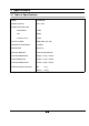
2. Specifications 2-1 Table of Specifications TIMER 35 MINUTES POWER SOURCE 230V ~50Hz POWER CONSUMPTION MICROWAVE 1100W Grill 1000W Combined mode 2100W OUTPUT POWER 100W/750W (IEC-705) OPERATING FREQUENCY 2,450MHz MAGNETRON OM75S(31) COOLING METHOD COOLING FAN MOTOR OUTSIDE DIMENSIONS 489(W) x 275(H) x 392(D) OVEN DIMENSIONS 330(W) x 187(H) x 320(D) SHIPPING DIMENSIONS 557(W) x 329(H) x 451(D) SHIPPING WEIGHT APPROX. NET 15 kg GROSS 15.
3.
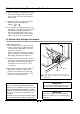
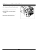
4. Disassembly and Reassembly 4-1 Replacement of Magnetron, Motor Assembly and Lamp Remove the magnetron including the shield case, permanent magnet, choke coils and capacitors (all of which are contained in one assembly). 1. 2. 3. 4. 5. 6. 7. 8. Disconnect all lead wires from the magnetron and lamp. Remove a screw securing air cover. Remove the air cover. Remove screws securing the magnetron to the wave guide. Take out the magnetron very carefully. Remove nuts from the back panel. Take out the fan motor.
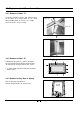
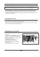
4-3 Replacement of Door Assembly 4-3-1 Removal of Door "C" Insert flat screwdriver into the gap between Door "A" and Door "C" to remove Door "C". Be careful when handling Door "C" because it is fragile. Then remove the door assembly. Door "A" Door "C" 4-3-2 Removal of Door "E" Door "E" Following the procedure as shown in the figure, insert and bend a thin metal plate between Door "E" and Door "A" until you hear the 'tick' sound. 1. Insertion depth of the thin metal plate should be 0.5mm or less.
4-3-4 Reassembly Test After replacement of the defective component parts of the door, reassemble it and follow the instructions below for proper installation and adjustment so as to prevent an excessive microwave leakage. 1. When mounting the door to the oven, be sure to adjust the door parallel to the bottom line of the oven face plate by moving the upper hinge and lower hinge in the direction necessary for proper alignment. 2.
4-6 Replacement of Control Circuit Board 4-6-1 Removal of Control Box Assembly 1. Disconnect the connectors from the control box assembly. 2. Remove screws securing the control box assembly. 3. Remove the knobs of the control box A'ssy. SCREW 4. Remove the screw securing the timer.
5. Alignment and Adjustments PRECAUTION 1. High voltage is present at the high voltage terminals during any cook cycle. 2. It is neither necessary nor advisable to attempt measurement of the high voltage. 3. Before touching any oven components or wiring, always unplug the oven from its power source and discharge the high voltage capacitor. 5-1 High Voltage Transformer 1. Remove connectors from the transformer terminals and check continuity. 2.
5-3 High Voltage Capacitor Ω 1. Check continuity of the capacitor with the meter set at the highest resistance scale. 2. Once the capacitor is charged, a normal capacitor shows continuity for a short time, and then indicates 9M . 3. A shorted capacitor will show continuous continuity. 4. An open capacitor will show constant 9M . 5. Resistance between each terminal and chassis should read infinite. Ω 5-4 High Voltage Diode 1. Isolate the diode from the circuit by disconnecting its leads. 2.
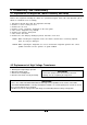
5-6 Output Power of Magnetron CAUTION MICROWAVE RADIATION PERSONNEL SHOULD NOT ALLOW EXPOSURE TO MICROWAVE RADIATION FROM MICROWAVE GENERATOR OR OTHER PARTS CONDUCTING MICROWAVE ENERGY. The output power of the magnetron can be measured by performing a water temperature rise test. Equipment needed : * Two 1-liter cylindrical borosilicate glass vessel (Outside diameter 190 mm) * One glass thermometer with mercury column NOTE: Check line voltage under load. Low voltage will lower the magnetron output.
5-8 Procedure for Measurement of Microwave Energy Leakage 1) Pour 275±15cc of 20±5° C(68±9° F) water in a beaker which is graduated to 600cc, and place the beaker in the center of the oven. 2) Start to operate the oven and measure the leakage by using a microwave energy survey meter. 3) Set survey meter with dual ranges to 2,450MHz. 4) When measuring the leakage, always use the 2 inch spacer cone with the probe. Hold the probe perpendicular to the cabinet door.
6. Troubleshooting WARNING FOR HIGH VOLTAGE 4000 VOLTS EXIST AT THE HIGH VOLTAGE AREA. DO NOT OPERATE THE OVEN WITH CABINET PARTS REMOVED. DO NOT REMOVE THE CABINET PARTS IF THE POWER SUPPLY CORD IS PLUGGED IN THE WALL OUTLET. UNPLUG THE POWER CORD BEFORE SERVICING. 6-1 Electrical Malfunction Parts Fuse blows out when door is opened. Fuse is Open Oven lamp does not light. Fan does not operate. Cause Diagnosis Remedy Defective primary interlock switch ary winding.
6-1 Electrical Malfunction(continued) part Cause 1) Too small a load Diagnosis Remedy If a small amount of food is heated for a long time, period of microwave may turn off during operation. Microwave turns off during cooking cycle. To increase the oven water into water into the oven. 2) Defective magnetron Check to see if the magnetron thermal cutout switch Replace thermal cutout thermal is activated at a temperature higher than 150 . switch. ℃ cutout S/W properly shock is felt.
6-2 Unsatisfactory Cooking Parts Cause 1) Open cathode of magnetron Diagnosis Remedy Check the terminals with a multimeter to see Replace magnetron. if the heater circuit is open. Check the H. V. Diode for continuity in the reverse and 2) Defective H. V. Diode normal directions using megger. If there is continuity in the reverse direction, the H. V. Diode may be faulty. Replace H. V. Diode. (In this event H. V.
7.
7-2 Main Parts List No. Code No. Q'ty Remark B001 3405-001034 SWITCH-MICRO Description 125/250VAC,16A,200GF,SPST-N Specification 1 PRI B002 3405-001032 SWITCH-MICRO 125/250VAC,16A,200GF,SPDT 1 B006 DE72-00138A BODY-LATCH NC2000(0.6/0.8/1.2),PP,-,-,-, 1 B009 DE66-00088A LEVER-SWITCH NC2000(0.6/0.8/1.2),PP,-,-, 1 B018 DE96-00115C ASSY BODY LATCH CE2611N,NC2000(BUTTON) 1 M001 DE70-00184P PANEL-OUTER MW850WA,C/STEEL,T0.
7-3 Control & Door Parts List No. Code No. C005 DE72-00176D CONTROL-PANEL Description G2711N/XET,ABS,-,-,-,-,PUR Specification 1 C006 DE61-70076A SPRING-BUTTON -,HSWR,PI0.
7-4 Standard Parts List Code No.
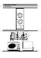
8. Schematic Diagrams 8-1 Schematic Diagrams MAGNETRON HIGH VOLTAGE DIODE FA TO CHASSIS F HIGH VOLTAGE CAPACITOR RED RED RED H.V.
ELECTRONICS © Samsung Electronics Co., Ltd. May 2003 Printed in Korea Code No.