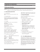
COLOR MONITOR CF21M* SERVICE Manual COLOR MONITOR CONTENTS 1. Precautions 2. Product Specifications 3. Disassembly & Reassembly 4. Alignment & Adjustments 5. Troubleshooting 6. Exploded View & Parts List 7. Electrical Parts List 8. Block Diagram 9. Wiring Diagram 10.
1 Precautions 1-1 Safety Precautions WARNINGS 1. For continued safety, do not attempt to modify the circuit board. 2. Disconnect the AC power before servicing. 3. When the chassis is operating, semiconductor heatsinks are potential shock hazards. 1-1-1 2. Inspect all protective devices such as nonmetallic control knobs, insulating materials, cabinet backs, adjustment and compartment covers or shields, isolation resistor-capacitor networks, mechanical insulators, etc. 3.
2 Product Specifications 2-1 Specifications Description Item Picture Tube: 21-Inch (53 cm): 20-inch (50.8 cm) viewable, 21”: 0.25 mm Dot pitch. Full-square tube / Perfect Flatmess, 90˚ Deflection, Anti-Reflection coating with Anti-electrastatic, Medium short persistence phosphor Scanning Frequency Horizontal : 30 kHz ~ 115 kHz Display Colors Unlimited colors Maximum Resolution Horizontal : 1800 Pixels, Input Video Signal Analog, 0.
3 Disassembly and Reassembly This section of the service manual describes the disassembly and reassembly procedures for the CF21M* monitor. WARNING: This monitor contains electrostatically sensitive devices. Use with caution when handling these components. 3-1 Disassembly Cautions:1. Disconnect the monitor from the power source before disassembly. 2. To remove the Rear Cover, you must use the special opening jig tool. 3-1-1 Before making Disassembly 3-1-5 Removing the Bottom Shield 1.
4 Alignment and Adjustments This section of the service manual explains how to make permanent adjustments to the monitor. 4-1 Adjustment Conditions Caution: Changes made without the Softjig are saved only to the user mode settings. As such, the settings are not permanently stored and may be inadvertently deleted by the user. 4-1-1 Before Making Adjustments 4-1-1 (a) ORIENTATION When servicing, always face the monitor to the east.
5 Troubleshooting 5-1 Parts Level Troubleshooting Notes: 1. If a picture does not appear, Click the Brightness and Contrast button on the front panel, and then increase the value of Brightness and Contrast. 2. Check the following circuits. • No raster appears: Power circuit, Horizontal output circuit, H/V control circuit, and H/V output circuit. • High voltage develops but no raster appears: Video output circuits. • High voltage does not develop: Horizontal output circuits.
6 Exploded View and Parts List CF21M* 6-1
7 Electrical Parts List 7-1 Main PCB Parts Loc. No. C414 C415 C602 C607 C701 CIS CIS CIS CIS CIS CIS CIS CIS CIS CN201 CN202 CN204 CN205 CN211 CN212 CN401 CN409 CORE_1 CORE_2 D402 D456 D505 D507 D647 FG601 G2_EY599 H/S+FBT HS402_CLAMP HS504_CLAMP IC201 IC201_SOCK IC250 IC403 IC620 JW01 L402 L403 L503 L601 L701 LC601 M/PCB+B/M-PCB POS601 R400 R401 R403 R407 CF21M* Code No.
CF21M* S-CORRECTION SOG LED H-SYNC V-SYNC AC INPUT 90-264VAC 60/50Hz AC INLET SOCKET H-SYNC TRIGGER MENU KEY MICROPROCESSOR ST72T774 CRYSTAL 24MHz D-COIL DEGAUSS OPERATION ACL CLAMP TILT MOIRE H_LIN. RECTIFIER D3SBA60 SWITCHING TRANS POWER OFF CONTROL POWER SYNC PWM CONTROL & SWITCHING FET DP408 LINE FILTER PFC CONTROL BNC/D-SUB R.G.B H-SYNC V-SYNC INPUT SDA/SCL H-SYNC/ V-SYNC OUT S-RASTER DDC-DATA DDC-CLK DEGAUSS -14V_I -14V +6.
9 Wiring Diagram H_CG H_CG V_CG V_CG CN103 Video PCB 1 2 3 4 5 6 7 8 9 10 11 12 13 14 15 1 2 3 4 5 6 7 8 9 10 11 12 13 14 15 H_SYNC_OUT +5V +12V +80V 6.3V GND G1 CN201 GND H_FLB V_SYNC_OUT CLAMP SCL SDA ABL DC_FOCUS CN204 KEY 1 GND KEY 2 GND 1 2 3 4 CONTROL PCB 1 KEY 1 2 GND KEY 1 3 GND 4 GND BLUE GND GREEN GND RED NC 1 2 3 4 5 6 7 1 2 3 4 5 6 GND BLUE GND GREEN GND RED 1 2 3 4 H_SYNC_OUT +5V +12V +80V +6.
10 Schematic Diagrams 10-1-1 Main Part Schematic Diagram CN201 slcon15p 1 2 +5V 3 +12V BD280 C280 R284 IC280 100nF 1/6W 1 8 2 7 3 6 4 5 MO 4 100 KS24C080 50V B +80V 5 +6.3V W_PROTECT 6 SCL R280 100 7 G1 1/6W 8 +12V H_FLB +5V_1 ZD201 12K MTZ7.5C C207 1/6W 1/2W 10 11 CLAMP 12 SCL 16V 50V 13 100nF Delete on CF21M 1.5K V_SYNC_OUT 100UF 100nF 1/6W 100 +5V_1 C202 C201 R220 9 SDA R281 RESET R282 SDA 50V R211 IC201 MO R243 R242 R240 R238 3.3K 3.
Copyright Trademarks © 2001 by Samsung Electronics Co., Ltd. Samsung is the registered trademark of Samsung Electronics Co., Ltd. All rights reserved. This manual may not, in whole or in part, be copied, photocopied, reproduced, translated, or converted to any electronic or machine readable form without prior written permission of Samsung Electronics Co., Ltd. CF21M* Service Manual First edition November 2001. CF21M* and MacMaster Cable Adapter are trademarks of Samsung Electronics Co., Ltd.
10 Schematic Diagrams 9 IC250, #24 10-2 10 IC250, #23 13 2.20 V (IC250, #11, 32) 16 3.42 V (IC201, #33) 17 3.16 V (IC201, #32) CH1 P-P = 2.20 V CH1 RMS = 2.776 V CH1 P-P = 3.42 V CH1 RMS = 2.500V CH1 P-P = 3.16 V CH1 RMS = 2.
10 Schematic Diagrams 10-1-2 Main Part Schematic Diagram +12V +350V +30V HIGH_VOLTAGE 14 +80V SCREEN FOCUS(RED) FOCUS(WHT) L502 -210V D598 4.7uH SCREEN RGP02-12(T) C503 L501 1 470uF 33uH EY503 16V C513 D505 C505 100uF 10nF 16V 50V GUR460L-5700 IC501 D504 Q502 TL494CN -210V 9 10 1/4W 12 13 +30V 1SS244 75K 1/4W 15nF 250V R522 270K 1/4W 1/4W 17/19NS 1/8W 470 2N3906 1 R504 X-RAY 5 10 6 9 1/6W C512 D509 33K 47uF UF4004 0.
10 Schematic Diagrams 2 IC402, #6 3 Q454, drain CH1 P-P = 10.96 V CH1 RMS = 6.180 V 7 Q402, Collector 4 Q401, Gate 5 Q401, Drain 6 Q402, Base 12 Q504, Gate 14 580 V (T501, #1) CH1 P-P = 11.6 V CH1 RMS = 6.944V 8 T402, #8 11 IC301, #6 CH1 P-P = 580 V CH1 RMS = 278.
10 Schematic Diagrams 10-1-3 Main Part Schematic Diagram CEPHEUS PROJECT POWER CIRCUIT WARING: BEFORE SERVICING THIS CHASSIS, READ "X-RAY RADIATION PRECAUTION,SAFETY CAUTION WARNING: 1. THE AREAS MARKED WITH A "THIS EQUIPMENT CONTAINS SAFETY CRITICAL COMPONTS ALL PARTS SHOWN IN THE SHADED IN THE SCHEMATIC DIAGRAM AND THE PARTS LIST DESIGNATE COMPONENT PRECAUTION, PRODUCT SAFETY NOTICE".
10 Schematic Diagrams 1 368 V (IC601, #1) 10-6 CF21M*
10 Schematic Diagrams 10-2 Video Part Schematic Diagram +5V 12V 5V Q105 KTA1281-Y BD111 4 21 1D 2H 1E 2I 1F 2J 1G 2K 1H 2L 1I 2M 1J 2N 1K 1N 5 8 1/10W ZD103 BZX79C5V6 R142 330 1/10W 13 1L ACL_ADJ C137 4.7uF 50V 10K C131 100nF 25V MO 12V C133 1uF 50V 12V_B CR01 100nF 25V 80V 2 CG01 100nF 25V 3 4 3 CB01 100nF 25V RB02 22 1/10W 4 5 6 RB01 75 1/10W RG01 75 1/10W RR01 75 1/10W DR02 1N4148 DG02 1N4148 DB02 1N4148 C103 100UF 16V C102 6.
10 Schematic Diagrams 15 CRT Socket, Red, Green, Blue 10-8 19 IC103, #5, 24 20 R, G, B, Video CF21M*
10 Schematic Diagrams 10-3 BNC Part Schematic Diagram +5V DB51 1N4148 +5V_DDC +5V DG51 1N4148 +3.3V +5V C151 100nF 50V MO DR51 1N4148 C159 10uF 25V UPSTREAM slcon6p C160 100nF 50V MO ZD159 UZ-6.2BM CN104 slcon5p 1 SELECTOR 5 2 USB_DM 4 3 4 3 ZD160 UZ-6.
10 Schematic Diagrams Memo 10-10 CF21M*
9 Wiring Diagram Memo 9-2 CF21M*
8 Block Diagrams Memo 8-2 CF21M*
7 Electrical Parts List Loc. No. R516 R608 RL601 T401 T402 T501 T502 T601 T620 T701 TH601 VR401 BD201 BD202 BD203 BD204 BD205 BD206 BD207 BD208 BD280 BD401 BD532 BD602 BD603 BD604 BD651 BD652 BD653 C201 C202 C203 C204 C208 C209 C210 C211 C212 C213 C214 C216 C220 C250 C251 C252 C253 C254 C255 C256 C257 C258 C259 C260 C264 C265 7-2 Code No.
7 Electrical Parts List Loc. No. C266 C268 C269 C270 C272 C280 C281 C283 C284 C285 C286 C301 C302 C303 C304 C305 C306 C307 C308 C309 C310 C312 C401 C402 C403 C404 C405 C406 C407 C408 C409 C410 C411 C413 C416 C417 C418 C440 C450 C451 C452 C453 C454 C456 C457 C458 C459 C460 C461 C462 C463 C464 C465 C466 C467 CF21M* Code No.
7 Electrical Parts List Loc. No. C468 C501 C502 C503 C504 C505 C506 C507 C508 C509 C510 C511 C512 C513 C514 C516 C520 C530 C531 C532 C533 C540 C550 C551 C552 C559 C562 C598 C599 C603 C604 C608 C609 C610 C611 C612 C613 C614 C620 C621 C622 C624 C625 C627 C628 C629 C641 C642 C643 C644 C645 C646 C649 C650 C651 7-4 Code No.
7 Electrical Parts List Loc. No. C652 C653 C654 C655 C656 C702 C703 C705 C706 C708 CN209 CN210 CN407 CN408 CN414 CN415 CN416 CN417 CN420 CN421 CN601 CN602 CN603 CN608 CN609 D201 D202 D250 D254 D281 D282 D301 D302 D303 D401 D405 D406 D407 D408 D450 D451 D452 D453 D454 D478 D501 D503 D504 D508 D509 D510 D520 D521 D522 D523 CF21M* Code No.
7 Electrical Parts List Loc. No. D530 D532 D540 D551 D552 D553 D561 D598 D599 D602 D604 D605 D606 D620 D621 D640 D642 D644 D646 D650 D670 D702 D703 D704 EY301 EY302 EY401 EY402 EY403 EY404 EY405 EY408 EY409 EY410 EY411 EY412 EY413 EY415 EY420 EY440 EY441 EY501 EY502 EY503 EY504 EY505 EY506 EY507 EY508 EY509 EY510 EY511 EY512 EY550 EY599 7-6 Code No.
7 Electrical Parts List Loc. No. EY6 EY601 EY602 EY603 EY604 EY607 EY608 EY609 EY61 EY610 EY611 EY612 EY613 EY614 EY615 EY616 EY703 EY704 EY705 FH601 IC280 IC402 IC501 IC621 IC701 JP104 JP106 JP113 JP114 JP116 JP150 JP151 JP153 JP154 JP158 JP159 JP167 JP178 JP184 JP186 JP187 JP189 JP190 JP191 JP192 JP193 JP194 JP197 JP198 JP204 JP210 JP212 JP213 JP216 JP227 CF21M* Code No.
7 Electrical Parts List Loc. No. JP239 JP245 JP266 JP267 JP268 JP269 JP275 JP276 JP289 JP294 JP295 JP297 JP302 JP303 JP307 JP308 JP323 JP324 JP327 JP328 JP334 JP335 JP337 JP340 JP344 JP346 JP361 JP362 JP363 JP365 JP371 JP372 JP375 JP376 JP377 JP378 JP379 JP381 JP383 JP390 JP397 JP399 JP402 JP404 JP412 JP415 JP416 JP417 JP418 JP419 JP421 JP425 JP439 JP440 JP441 7-8 Code No.
7 Electrical Parts List Loc. No. JP451 JP453 JP454 JP455 JP460 JP481 JP483 JP486 JP487 JP491 JP511 JP516 JP522 JP546 JP547 JP548 JP572 JP578 JP579 JP585 JP587 JP588 JP590 JP591 JP596 JP597 JP598 JP603 JP615 JP616 JP617 JP619 JP623 JP626 JP629 JP630 JP633 JP635 JP637 JP638 JP640 JP643 JP644 JP645 JP647 JP648 JP649 JP650 JP651 JP652 JP653 JP654 JP655 JP656 JP657 CF21M* Code No.
7 Electrical Parts List Loc. No. JP659 JP660 JP661 JP662 JP663 JP664 JP665 JP666 JP670 JP678 JP680 JP681 JP682 JP683 JP684 JP685 JP686 JP687 JP688 JP691 JP695 JP697 JP699 JP701 JP702 JP703 JP705 JP706 JP713 JP714 JP715 JP716 JP718 JP719 JP720 JP722 L400 L501 L502 MP1.0 Q250 Q251 Q252 Q301 Q408 Q409 Q410 Q411 Q412 Q450 Q451 Q452 Q453 Q502 Q503 7-10 Code No.
7 Electrical Parts List Loc. No. Q520 Q521 Q540 Q553 Q601 Q620 Q670 Q671 Q672 R200 R203 R204 R205 R206 R207 R208 R209 R210 R211 R215 R216 R218 R219 R220 R221 R222 R225 R226 R227 R228 R229 R230 R231 R233 R236 R237 R238 R239 R240 R242 R243 R250 R251 R252 R253 R254 R255 R256 R261 R264 R265 R266 R267 R268 R269 CF21M* Code No.
7 Electrical Parts List Loc. No. R270 R271 R272 R273 R274 R278 R280 R281 R282 R284 R285 R286 R301 R302 R303 R304 R305 R306 R307 R308 R309 R310 R311 R312 R313 R314 R315 R316 R402 R404 R405 R406 R408 R409 R410 R412 R413 R414 R420 R421 R422 R423 R424 R425 R426 R427 R428 R429 R430 R431 R432 R433 R434 R440 R441 7-12 Code No.
7 Electrical Parts List Loc. No. R450 R451 R452 R453 R454 R455 R456 R457 R459 R460 R461 R462 R463 R464 R465 R466 R467 R468 R490 R501 R502 R503 R504 R505 R506 R507 R508 R509 R510 R511 R512 R515 R520 R521 R522 R523 R524 R525 R526 R527 R531 R532 R541 R542 R543 R545 R546 R547 R550 R551 R552 R553 R555 R556 R557 CF21M* Code No.
7 Electrical Parts List Loc. No. R558 R560 R561 R596 R597 R598 R599 R601 R602 R603 R604 R605 R606 R607 R609 R620 R621 R622 R623 R624 R625 R626 R627 R628 R629 R630 R631 R644 R649 R651 R655 R656 R668 R670 R671 R672 R673 R674 R675 R676 R677 R688 R701 R702 R703 R704 R705 R706 R711 R712 R721 SK530 X201 ZD201 ZD203 7-14 Code No.
7 Electrical Parts List Loc. No. Code No. Description Specification Remarks ZD204 ZD236 ZD286 ZD450 ZD520 ZD521 ZD601 ZD630 ZD631 ZD705 ZD706 0403-000361 0403-001068 0403-000361 0403-000004 0403-001068 0403-000367 0403-000753 0403-000367 0406-001062 0403-000004 0403-000538 DIODE-ZENER DIODE-ZENER DIODE-ZENER DIODE-ZENER DIODE-ZENER DIODE-ZENER DIODE-ZENER DIODE-ZENER DIODE-TVS DIODE-ZENER DIODE-ZENER UZ6.2BSB,6.2V,5.99-6.24V,500mW UZ4.7BSA,4.7V,4.47-4.65V,500mW UZ6.2BSB,6.2V,5.99-6.
7 Electrical Parts List Loc. No. Code No.
7 Electrical Parts List 7-2 Video PCB Parts Loc. No. ]CIS CIS CIS CIS CIS CIS CIS CIS CIS CIS CIS CIS CIS CN101 CN102 CN104 CN105 H/S+SH/VID HS102 IC102 IC106 SH/VID SH/VID SK105 C100 C105 C106 C107 C108 C109 C110 C111 C119 C123 C128 C129 C130 C134 C136 CB02 CB03 CG02 CG03 CR02 CR03 IC103 R111 R112 R113 R114 R115 R116 R117 R118 CF21M* Code No.
7 Electrical Parts List Loc. No. R119 R120 R121 R122 R124 R125 R126 R128 R129 R130 R131 R132 R133 R134 R135 R137 R138 R139 R140 R141 R142 R143 R144 RB01 RB02 RB04 RB05 RB06 RB08 RG01 RG02 RG04 RG05 RG06 RG08 RR01 RR02 RR04 RR05 RR06 RR08 BD101 BD102 BD103 BD104 BD105 BD106 BD108 BD109 BD111 C104 C112 C113 C116 C117 7-18 Code No.
7 Electrical Parts List Loc. No. C118 C120 C121 C122 C124 C125 C126 C127 C132 C133 C135 C137 C138 C139 C140 C141 C144 CB04 CB06 CG04 CG06 CN12 CN13 CN14 CR04 CR06 D101 DB01 DB02 DB03 DB04 DB05 DG01 DG02 DG03 DG04 DG05 DR01 DR02 DR03 DR04 DR05 EY1 EY2 EY5 EY6 EY7 EY8 IC104 JP1 JP100 JP101 JP102 JP103 JP104 CF21M* Code No.
7 Electrical Parts List Loc. No. JP105 JP106 JP109 JP11 JP110 JP12 JP13 JP17 JP18 JP19 JP20 JP21 JP22 JP23 JP24 JP27 JP29 JP32 JP37 JP4 JP44 JP49 JP5 JP50 JP51 JP53 JP54 JP57 JP6 JP60 JP61 JP62 JP63 JP64 JP65 JP66 JP67 JP68 JP69 JP7 JP70 JP74 JP75 JP8 JP82 JP86 JP87 JP89 JP90 JP91 JP92 JP93 JP94 JP95 JP97 7-20 Code No.
7 Electrical Parts List Loc. No. Code No. Description Specification JP98 JP99 L100 L101 L106 LB01 LG01 LR01 MP1.
7 Electrical Parts List 7-3 MISC PCB Parts Loc. No. MISC B/BNC+SH/BNC CIS CIS CIS CIS CIS CIS CIS CN101_ASSY CN103 CN104 CN105 IC1 BD150 BD151 C132 C133 C151 C152 C159 C160 C95 C96 C97 C98 CB51 CB52 CB53 CG51 CG52 CG53 CR51 CR52 CR53 DB51 DB52 DB53 DB54 DG51 DG52 DG53 DG54 DR51 DR52 DR53 DR54 EY101 EY102 EY103 EY104 EY105 IC3 JP107 JP108 7-22 Code No.
7 Electrical Parts List Loc. No. JP109 JP110 JP111 JP112 JP115 JP117 JP118 JP119 JP120 JP121 JP122 JP123 JP125 JP126 JP127 JP128 JP131 JP132 JP160 JP161 JP162 JP163 JP164 JP165 JP166 JP168 JP170 JP171 MP1.0 QB52 QG52 QR52 R100 R137 R154 R155 R159 R160 R95 R96 R97 R98 R99 RB51 RB52 RB53 RB54 RB55 RG51 RG52 RG53 RG54 RG55 RR51 RR52 CF21M* Code No.
7 Electrical Parts List Loc. No. RR53 RR54 RR55 ZD151 ZD152 ZD153 ZD154 ZD155 ZD156 ZD157 ZD158 ZD159 ZD160 ZD161 Code No. 2001-000969 2001-000302 2001-000527 0403-000361 0403-000361 0403-000361 0403-000361 0403-000361 0403-000361 0403-000361 0403-000361 0403-000361 0403-000361 0403-000361 Description R-CARBON R-CARBON R-CARBON DIODE-ZENER DIODE-ZENER DIODE-ZENER DIODE-ZENER DIODE-ZENER DIODE-ZENER DIODE-ZENER DIODE-ZENER DIODE-ZENER DIODE-ZENER DIODE-ZENER Specification Remarks 75OHM,5%,1/8W,AA,TP,1.
7 Electrical Parts List 7-5 S-Corretion Table S1 ~114.9 ~104.9 ~99.9 ~94.9 ~91.9 ~84.9 ~80.9 ~77.9 ~75.9 ~69.9 ~67.9 ~64.9 ~60.9 ~58.9 ~54.9 ~50.9 ~45.9 ~39.9 ~36.9 ~34.
7 Electrical Parts List Memo 7-26 CF21M*
7 Electrical Parts List Loc. No. CF21M* Code No.
6 Exploded View & Parts List Memo 6-2 CF21M*
5 Troubleshooting 5-1-2 PFC Failure Check the Voltage at IC701 Pin5. The Voltage is around 10VDC? No Check and Replace D702, R711, ZD705, ZD706. WAVEFORMS 1 368 V (IC601, #1) Yes 1 Q701 Gate waveform is right? No Replace IC701. Yes Check the Voltage at D701 cathode. The Voltage is about 400VDC? No Replace Q701, D701. Yes Done. 5-1-3 DPMS Failure Check signal source H/V sync. video signal. Make No H/V sync. ( That is power off mode).
5 Troubleshooting 5-1-4 H_Deflection Failure 2 IC402 Pin 6 waveform is right? No 1. Appear the Voltage 12VDC at IC402 Pin 7 replace R451. 2. Check IC402 Pins 6~5, 7~6. 3. Replace IC402. Yes Q454 drain waveform is right? 3 No Check Q451, Q452, Q453, ZD450, R467, D456. No Check Q250, Q251, IC250 Check +19V line. No Check and replace D402 and Q402. Check DY connector connection.
5 Troubleshooting 5-1-5 S Correction Failure Check S1 ~ S5 signal. Refer to the S-corrction table page? S1~S5 signals are right at each frequency block? No Check and replace IC201. Yes Check and replace C411, C413, C414, C415, C416, C417, C418, Q403 ~ Q407, Q408 ~ Q412 5-1-6 H_Lin. Failure IC201 Pin 3 voltage varies with different H_Lin. DAC values? No Replace IC201. Yes IC403 Pin 7, 8 voltage varies with different H_Lin. DAC values? No Check +12 V line. Check some parts around IC403.
5 Troubleshooting 5-1-8 Abnormal H_Size WAVEFORMS The Voltage waveforms at Q402 Collector are right? 7 No Repeat the troubleshooting Guide of H_deflection failure. 7 Q402, Collector Yes T402 pin 8 wareform is right? 8 No Replace T402. Yes 8 T402, #8 Check some parts around IC250 and IC402 Pin 1 and 2. 5-1-9 Side Pin or Trap Failure IC250 Pin 24 output exists? The waveform is right? 9 No Check and replace IC250. Yes Check and replace IC402. Check some parts IC402 Pin 2 and IC250 Pin 24.
5 Troubleshooting 5-1-11 Tilt Failure Check tilt connector connection IC201 Pin 5 output duty varies with different DAC values? No Check and replace IC201. Yes IC403 Pin 10, 11 output varies with different DAC values? No Check and replace IC403. Yes Check and replace CRT. 5-1-12 V Deflection Failure Is 14V at IC301 Pin 2? Is -14V at IS301 Pin 5? No Check and replace R312, R316. Refer to 5-1-1 No Power supply.
5 Troubleshooting 5-1-13 V Size or Pos. Variation Failure IC250 Pin 23 output varies with different DAC values? No Check some parts around IC250. Check bias voltage. No Check +12 V line. Check and replace Q502, Q503, R511, IC501. Yes Check and replace IC250 and IC301.
5 Troubleshooting 5-1-15 ABL Failure Input full white pattern to monitor. IC102 Pin12 (19”: IC101, Pin15) input exists and varies with different patterns? Yes Check and replace IC102 (19”:IC101). No Check CN102, Q101, Q102, ZD101. T501 Pin 8 Voltage exists? No Check and replace T501. Yes IC103 Pin 16 output exists and varies with different patterns? No Check and replace IC103.
5 Troubleshooting 5-1-17 No Video WAVEFORMS Check signal cable and connection. 15 CRT Socket, Red, Green, Blue IC101 Pins 2, 4 and 6 (19”: IC105, Pins 2, 4 and 6) inputs are right? No Check CN101, IC1, QR51, QG51, QB51, and IC3 on BNC Board. No Check Vcc on IC101 (19”: IC105) and replace IC101 (19”: IC105). No Check +12 V line. Check and replace IC102 (19”: IC101).
5 Troubleshooting 5-1-18 Micom Failure IC201 Pin 13 input is over 4.2V? No WAVEFORMS Check IC650. 16 3.42 V (IC201, #33) Yes 16 17 IC201 Pin 32 and 33 inputs are right? No Check X201, C203 and C204. Yes CH1 P-P = 3.42 V CH1 RMS = 2.500V IC201 Pin 40 input is High Active? No Check and replace IC202. 17 3.16 V (IC201, #32) Yes All in/output values are right? Yes No Replace IC201. CH1 P-P = 3.16 V CH1 RMS = 2.560 V Done.
5 Troubleshooting 5-1-19 OSD Failure WAVEFORMS Check CN102 and connector Ass’y. 18 IC103, #6, 17 IC103 (19”: IC03) Pin 6 and 17 18 19 waveforms are right? Is there 5V on IC103 Pin 5 and 24? No Check and replace Q104, IC201 Pin 20. Check 5V Line. Yes IC102 Pins 1, 2 and 3, 4 (19”: IC101 Pins 1, 4 and 9, 13) input is right? No Check and replace IC103 (19”:IC103). 19 IC103, #5, 24 Yes Does the Voltage Change on IC201 Pins 11, 12 When you push the control Button? No Check CN204 and Assy.
5 Troubleshooting 5-1-20 User Control Failure Check connector Ass’y. IC201 Pins 11 and 12 inputs are right at each function? No Check and replace function key. Yes Check and replace IC201. Done. 5-1-21 Degaussing Failure Check degaussing connector. RL601 operation is right? Yes Check D-Coil, POS601. No Q601 base input is right? Yes Check and replace Q601. No IC201 Pin 31 output is right? No Check and replace IC201. Check user function key. Yes Done.
5 Troubleshooting 5-2 General Troubleshooting 5-2-1 No Picture LED blinks? Yes Go to 5-2-2 Shut down troubleshooting guide. WAVEFORMS 20 R, G, B, Video No G2 Voltage is right? No Check D598, D599 and G2 wire. Also check around FBT circuits. Yes Heater Voltage is right? No Check CN201 Assy and D642, Q672. Yes 20 R, G, B Cathode is right? No Return back the No Video (5-1-16) troubleshooting guide. Yes Check SDA (IC201 Pin 30) and SCL (IC201 Pin 29) Replace IC280, IC201.
5 Troubleshooting 5-2-3 Missing Color Proper Video levels are on CN101 Pin 1, 3 and 5. No Check signal generator and replace BNC Board. Yes Proper AC voltage are on all cathodes? No Refer to 5-1-16 No Video. Yes Proper DC voltage are on all cathodes? No Check IC105 (19”: IC102) Pin 1, 3 and 5. Check and replace IC105 (19”: IC102) and IC104 (19”: IC104). Yes G2 voltage is right? No Check D598, D599 and G2 wire. Check around FBT circuits also. Yes Change the CRT. Done.
5 Troubleshooting 5-2-4 Visible Retrace Check white balance adjustment. G2 voltage is right? No Check G2 control volume and FBT. Yes Blank pulse is on Pin 23 of IC102 (19”: Pin 27 of IC101) on Video board? No Check CN102, Q104 (19”: Q103). Yes Blank pedestal is on Pin 25, 28 and 30 of IC102 (19”: 29, 32 and 35 of IC101)? No Check IC102 (19”: IC101) and related components. No Check Q301, CN102 Assy, Q520, D520, and D521. Yes Is V_FLB and DC_bias on G1 Pin at CRT socket? Yes Done.
5 Troubleshooting 5-2-5 Unsynchronized Image Compare input sync. of IC201 Pin 18 and 19 with output sync. of IC201 20 and 21. Are they all right? No Check and replace IC201. Yes Are H_Out and V_Out of IC250 Pin 23 and 26 right? No Check and replace IC250. Yes Are H_FLYBACK of IC102 Pin 23 (19”: IC101 Pin 27) right? No Check CN102 Assy and Q103. Yes Check clamp pulse of IC102 Pin 22 (19”: IC101 Pin 19) replace IC201 and Q107. Done.
5 Troubleshooting 5-2-6 Misconvergence Are the C/G control circuits in the video Board? (AQ17NS, AQ17NS, AQ19FS have the C/G control circuits in the video Board) No Try readjusting convergence. The convergence is now within spec.? No Yes Change CRT and readjust convergence. Yes Check the C/G control Assy (CN104, CN105). Proper voltage are appeared on IC106 Pin 7, 8, 10, and 11 in Video Board. Change CRT and readjust convergence. No Check and replace IC106. No Done. Done.
5 Troubleshooting 5-2-7 Poor Focus Adjust focus VR. Improved focus? Yes Aging monitor and check for focus change. No Refer to 5-1-15 Dynamic Focus Failure. No Check focus leads from FBT to CRT Socket. Check the CRT Socket. Dynamic focus circuit is right? Yes Replace the CRT and verify focus. 5-2-8 Purity Failure Degaussing Purity is right? Yes Done. No Degaussing circuit is right? No Refer to 5-1-20 Degaussing Failure. Yes Replace CRT and verify purity.
4 Alignment and Adjustments 4-2 Display Control Adjustments 4-2-1 Centering 4-2-1 (d) VERTICAL POSITION ADJUSTMENT Centering means to position the center point of the display in the middle of the display area. Horizontal size and position and vertical size and position control the centering of the display.
4 Alignment and Adjustments 4-2-2 (b) VERTICAL LINEARITY ADJUSTMENT CONDITIONS Scanning frequency: 91 kHz / 85 Hz Display image: Crosshatch pattern Brightness: Cut-off Contrast: Maximum To adjust the Vertical Linearity, refer to Table 4-1 for the tolerance range. Use control bar after selecting “V_LINEARITY BAL” in left menu to optimize the image.
4 Alignment and Adjustments 4-3 Color Adjustments 4-3-1 Color Coordinates (Temperature) Color temperature is a measurement of the radiant energy transmitted by a color. For computer monitors, the color temperature refers to the radiant energy transmitted by white. Color coordinates are the X and Y coordinates on the chromaticity diagram of wavelengths for the visible spectrum.
4 Alignment and Adjustments Luminance Table (9300K) 4-3 21” Without ABL 32ft-L Without ABL 28ft-L Without ABL (High Light is Activated) - 4-3-2 (d) WHITE BALANCE ADJUSTMENT VERIFICATION CONDITIONS Scanning frequency: Display image: X-Y Coordinates: Raster Luminance ABL Luminance Brightness: Contrast: 91 kHz / 85 Hz Back raster pattern x = 0.283 ± 0.02, y = 0.298 ± 0.02 0.3 ~ 1ft-L 30 ± 1 ft-L Cut-off Maximum 1. Check whether the color coordinates of the back raster satisfy the above spec.
4 Alignment and Adjustments 4-3-4 (c) WHITE BALANCE ADJUSTMENT CONDITIONS Scanning frequency: Display image: Brightness: Contrast: 91 kHz / 85 Hz Full white pattern Cut-off Maximum 1. Click on the << or >> boxes next to R_GAIN and B_GAIN to make the video white. (For 5000K color adjustment: x = 0.346 ± 0.02, y = 0.359 ± 0.02.) 2. Refer to the procedure for 9300K, section 4-3-2 (c) steps 2 and 3.
3 Disassembly and Reassembly 3-1-7 Removing the Video PCB Assembly Rear Shield and Video PCB 1. Remove the 3 screws on the PCB Assembly. 2. Remove the Video PCB Assembly Rear Shield. (5 point) 3. Lift out the Video PCB and pleat it on a flat, level surface that is protected from static electricity. 3-1-8 Removing the Main PCB Assembly 1. Remove both side screws (4 screws) on the lower edge of the CRT Bracket. 2. Remove Chassis Ground Wire on the both side. 3.
2 Product Specifications Table 2-1. Timing Chart Mode IBM Timing VESA VGA2/70Hz VGA3/60Hz 640/85 Hz 800/85 Hz 1024/85 Hz 1280/75 Hz 1280/85 Hz 1600/85 Hz 720 x 400 640 x 480 640 x 480 800 x 600 1024 x 768 1280 x 1024 1280 x 1024 1600 x 1200 fH (kHz) 31.469 31.469 43.269 53.674 68.677 79.976 91.146 106.250 A µsec 31.778 31.778 23.111 18.631 14.561 12.504 10.971 9.412 B µsec 3.813 3.813 1.556 1.138 1.016 1.067 0.016 0.837 C µsec 1.907 1.907 3.810 2.702 2.
1 Precautions 1-2 Servicing Precautions WARNING1: First read the “Safety Precautions” section of this manual. If unforeseen circumstances create conflict between the servicing precautions and safety precautions, always follow the safety precautions. WARNING2: A high voltage VR replaced in the wrong direction may cause excessive X-ray emissions. WARNING3: An electrolytic capacitor installed with the wrong polarity might explode. 1.
Samsung Electronics Co.,Ltd. 416, Maetan-3Dong, Paldal-Gu, Suwon City, Kyungki-Do, Korea. Printed in Korea P/N : BH81-00017A-00 http://www.samsungmonitor.com (SyncMaster Worldwide) http://www.samsung-monitor.com (SyncMaster USA) http://www.sec.co.