INSTALLATION INSTRUCTIONS OVER THE RANGE MICROWAVE OVEN BEFORE YOU BEGIN (Read these instructions completely and carefully.) • • • • • IMPORTANT Save these instructions for local inspector’s use. IMPORTANT Observe all governing codes and ordinances. Note to Installer - Be sure to leave these instructions with the Consumer. Note to Consumer - Keep these instructions for future reference. Skill level - Installation of this appliance requires basic mechanical and electrical skills.
Contents General information Step-by-step installation guide Important Safety Instructions . . . . . . . . . 3 Placement Of The Mounting Plate. . . . . . 8 Removing the Mounting Plate. . . . . . . . . 8 Finding the Wall Studs. . . . . . . . . . . . . . . 8 Determining Wall Plate Location . . . . . . . 9 Aligning the Wall Plate. . . . . . . . . . . . . . . 10 Electrical Requirements. . . . . . . . . . . . . . 3 Hood Exhaust . . . . . . . . . . . . . . . . . . . . . . 4 Damage - Shipment/installation. . .
General information IMPORTANT SAFETY INSTRUCTIONS Where a standard two-prong wall receptacle is encountered, it is very important to have it replaced with a properly grounded three-prong wall receptacle, installed by a qualified electrician. This product requires a three-prong grounded outlet. The installer must perform a ground continuity check on the power outlet box before beginning the installation to insure that the outlet box is properly grounded.
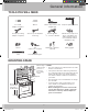
General information HOOD EXHAUST NOTE: Read these next two pages only if you plan to vent your exhaust to the outside. If you plan to recirculate the air back into the room, proceed to page 11. OUTSIDE TOP EXHAUST (EXAMPLE ONLY) The following chart describes an example of one possible ductwork installation. EQUIVALENT LENGTH x NUMBER USED = EQUIVALENT LENGTH Roof Cap 24 ft. x (1) = 24 ft. 12 Ft. Straight Duct (6” Round) 12 ft. x (1) = 12 ft. Rectangular-to-Round Transition Adaptor* 5 ft.
General information Maximum duct length: NOTE: If you need to install ducts, note that the total duct length of 3¼” x 10” rectangular or 6” diameter round duct should not exceed 140 equivalent feet. For satisfactory air movement, the total duct length of 3¼” x 10” rectangular or 6” diameter round duct should not exceed 140 equivalent feet. Outside ventilation requires a HOOD EXHAUST DUCT. Read the following carefully. Elbows, transitions, wall and roof caps, etc.
General information DAMAGE - SHIPMENT/INSTALLATION • If the unit is damaged in shipment, return the unit to the store in which it was bought for repair or replacement. • If the unit is damaged by the customer, repair or replacement is the responsibility of the customer. • If the unit is damaged by the installer (if other than the customer), repair or replacement must be made by arrangement between customer and installer.
General information TOOLS YOU WILL NEED # 1 and #2 Phillips screwdriver Pencil Tin snips (for cutting damper, if required) Scissors (to cut template, if necessary) Gloves Saw (saber, hole or keyhole) Level Duct and masking tape Ruler or tape measure and straight edge Electric drill with ½” and 5/8” drill bits 3/16”, Stud finder or Hammer (optional) Carpenter square (optional) Filler blocks or scrap wood pieces, if needed for top cabinet spacing (used on recessed bottom cabinet installations on
Step-by-step installation guide 1. PLACEMENT OF THE MOUNTING PLATE A. REMOVING THE MICROWAVE OVEN FROM THE CARTON/REMOVING THE MOUNTING PLATE B. FINDING THE WALL STUDS 1. Remove the installation instructions, Exhaust 7ALL 3TUDS adaptor, filters, glass tray and the small hardware bag. Do not remove the Styrofoam protecting the front of the oven. #ENTER 2. Fold back all 4 carton flaps fully against carton sides. Then carefully roll the oven and carton over onto the top side.
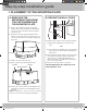
Step-by-step installation guide C. DETERMINING WALL PLATE LOCATION UNDER YOUR CABINET Plate position – beneath flat bottom cabinet Plate position – beneath framed recessed cabinet bottom 16-1/2" CL At least 30q Draw a vertical line on the wall at the center of the 30q wide space. Tape the Rear Wall Template onto the wall matching the centerline and touching the bottom of the cabinet. CL 30q to Cooktop Draw a vertical line on the wall at the center of the 30q space.
Step-by-step installation guide D. ALIGNING THE WALL PLATE Hole A Draw a Vertical Line on Wall from Center of Top Cabinet Centerline notches CL Horizontal Line Area E Hole B Horizontal Line Draw a Horizontal line on wall from bottom of “Rear Wall Template”. CAUTION: Wear gloves to avoid cutting CAUTION: Wear gloves to avoid cutting fingers on sharp fingers on sharp edges. edges. 1. Draw a Vertical line on the wall at the center of the 30" NOTE: Holes A, B and C are inside area E.
Step-by-step installation guide 2. INSTALLATION TYPES (Choose A, B or C) This microwave oven is designed for adaptation to the following three types of ventilation: A. B. C. Outside Top Exhaust (Vertical Duct) Recirculating (Non-Vented Ductless) Outside Back Exhaust (Horizontal Duct) A. OUTSIDE TOP EXHAUST (VERTICAL DUCT) NOTE: This microwave is shipped assembled for Outside Top Exhaust (except for non-vented models).
Step-by-step installation guide A. OUTSIDE TOP EXHAUST (Vertical Duct) INSTALLATION OVERVIEW A1. A2. A3. A4. A5. Attach Mounting Plate to Wall Prepare Top Cabinet Mount the Microwave Oven Adjust the Exhaust Adaptor Connecting Ductwork A1. ATTACH THE MOUNTING PLATE TO THE WALL NOTE: Before tightening toggle bolts and wood screw, make sure the tabs on the mounting plate touch the bottom of the cabinet when pushed flush against the wall and that the plate is properly centered under the cabinet.
Step-by-step installation guide A3. INSTALLATION PROCEDURE FOR EXHAUST ADAPTOR AND PROPER DAMPER OPERATION CHECK A4. MOUNT THE MICROWAVE OVEN FOR EASIER INSTALLATION AND PERSONAL SAFETY, WE RECOMMEND THAT TWO PEOPLE INSTALL THIS MICROWAVE OVEN. IMPORTANT: Do not grip or use handle during installation. Exhaust Adaptor and Damper is shipped assembled to the filler-upper. NOTE: If your cabinet is metal, use the nylon grommet around the power cord hole to prevent cutting of the cord.
Step-by-step installation guide A5. ADJUST THE EXHAUST ADAPTOR #ABINET &RONT #ABINET "OTTOM 3HELF &ILLER "LOCK Open the top cabinet and adjust the exhaust adaptor to connect to the house duct. %QUIVALENT TO $EPTH OF #ABINET 2ECESS "LOWER 0LATE "ACK OF -ICROWAVE $AMPER 3ELF !LIGNING 3CREW &OR &RONT TO "ACK OR 3IDE TO 3IDE !DJUSTMENT 3LIDE THE %XHAUST !DAPTOR AS .EEDED -ICROWAVE /VEN 4OP 4. Attach the microwave oven to the top cabinet. 5. Insert 2 self-aligning screws through outer top cabinet holes.
Step-by-step installation guide B. RECIRCULATING (Non-Vented Ductless) INSTALLATION OVERVIEW B1. B2. B3. B4. B5. Attach Mounting Plate to Wall Prepare Top Cabinet Adjust Blower Mount Microwave Oven Install Charcoal Filter B1. ATTACH THE MOUNTING PLATE TO THE WALL 3. Place the mounting plate against the wall and insert the toggle wings into the holes in the wall to mount the plate.
Step-by-step installation guide B3. ADAPTING MICROWAVE BLOWER FOR RECIRCULATION 4. Roll the blower unit 90° so that fan blade openings are facing toward the front of the microwave. 2. Lift up the BEFORE: Fan Blade Openings Facing UP blower plate. 1. Remove and save screw Back of Microwave that holds blower plate to microwave. NOTE: The exhaust adaptor with damper is not needed for recirculating models. You may want to save them for possible future use. 3. Carefully pull out the blower unit.
Step-by-step installation guide B4. MOUNT THE MICROWAVE OVEN #ABINET &RONT #ABINET "OTTOM 3HELF &ILLER "LOCK %QUIVALENT TO $EPTH OF #ABINET 2ECESS 3ELF !LIGNING 3CREW FOR EASIER INSTALLATION AND PERSONAL SAFETY, WE RECOMMEND THAT TWO PEOPLE INSTALL THIS MICROWAVE OVEN. -ICROWAVE /VEN 4OP IMPORTANT: Do not grip or use handle during installation. 4. Attach the microwave oven to the top cabinet. 5. Insert 2 self-aligning screws through outer top cabinet holes. Turn two full turns on each screw.
Step-by-step installation guide B5. INSTALLING THE CHARCOAL FILTER 1. Remove screws on top of grille using a #1 Phillips screwdriver. 2. Open the door. 3. Remove the grille. • After push left, Pull the straight off. Charcoal filter 4. Install the charocal filter. When properly installed, the wire mesh of the filter should be visible from the front. 5. Reinstall the grille and the screws. 6. Close the door. Insert mesh-side up 18 DE68-03587B-EN.
Step-by-step installation guide C. OUTSIDE BACK EXHAUST (Horizontal Duct) INSTALLATION OVERVIEW C1. C2. C3. C4. C5. Prepare Rear Wall Attach Mounting Plate to Wall Prepare Top Cabinet Adjust Blower Mount the Microwave Oven C1. PREPARING THE REAR WALL FOR OUTSIDE BACK EXHAUST You need to cut an opening in the rear wall for outside exhaust. CL • Read the instructions on the REAR WALL TEMPLATE. • Tape it to the rear wall. • Cut the opening, following the instructions of the REAR WALL TEMPLATE.
Step-by-step installation guide C2. ATTACH THE MOUNTING PLATE TO THE WALL C3. USE TOP CABINET TEMPLATE FOR PREPARATION OF TOP CABINET You need to drill holes for the top support screws, a hole large enough for the power cord to fit through, and a cutout large enough for the exhaust adaptor. Attach the plate to the wall using toggle bolts. At least one wood screw must be used to attach the plate to a wall stud. 1. Remove the toggle wings from the bolts. 2.
Step-by-step installation guide C4. ADAPTING MICROWAVE BLOWER FOR OUTSIDE BACK EXHAUST (cont.) 6. Place the blower unit back into the opening. AFTER: Fan Blade Openings Facing Back End A 3. Carefully pull out the blower unit. The wires will extend far enough to allow you to adjust the blower unit. End B BEFORE: Fan Blade Openings Facing Forward End B End A CAUTION: Do not pull or stretch the blower unit wiring. Make sure the wires are not pinched.
Step-by-step installation guide C5. MOUNT THE MICROWAVE OVEN #ABINET &RONT #ABINET "OTTOM 3HELF &ILLER "LOCK %QUIVALENT TO $EPTH OF #ABINET 2ECESS 3ELF !LIGNING 3CREW FOR EASIER INSTALLATION AND PERSONAL SAFETY, WE RECOMMEND THAT TWO PEOPLE INSTALL THIS MICROWAVE OVEN. -ICROWAVE /VEN 4OP IMPORTANT: Do not grip or use handle during installation. 4. Attach the microwave oven to the top cabinet. 5. Insert 2 self-aligning screws through outer top cabinet holes. Turn two full turns on each screw.
Before You Use Your Microwave 1. Make sure the microwave oven has been installed 6. Read the Owner’s Manual. according to instructions. 7. KEEP INSTALLATION INSTRUCTIONS FOR 2. Remove all packing material from the microwave THE LOCAL INSPECTOR’S USE. oven. 3. Install turntable and ring in cavity. 4. Replace house fuse or turn breaker back on. 5. Plug power cord into a dedicated 20 amp electrical outlet.
Code No.:DE68-03587B-02 Printed in Malaysia DE68-03587B-EN.
CONSIGNES D’INSTALLATION FOUR MICRO-ONDES À HOTTE INTÉGRÉE AVANT DE COMMENCER (Lisez attentivement l’intégralité des consignes.) IMPORTANT Conservez précieusement ce manuel en vue du passage éventuel d’un technicien en cas de réparation. IMPORTANT Respectez tous les codes et règlements en vigueur. • Remarque destinée à l’installateur - N’oubliez pas de laisser le manuel à l’utilisateur.
Sommaire Informations générales Guide d’installation étape par étape Consignes de sécurité importantes . . . . 3 Emplacement de la plaque de fixation . . 8 Retrait de la plaque de fixation . . . . . . . . 8 Détection des goujons. . . . . . . . . . . . . . . 8 Détermination de l’emplacement de la plaque murale . . . . . . . . . . . . . . . . . . . . . 9 Alignement de la plaque murale . . . . . . . 10 Exigences en matière de raccordement électrique. . . . . . . . . . . . . . . . . . . . . . . . . .
Informations générales Importantes consignes de securite Faites vérifier la prise murale et le circuit électrique par un électricien agréé pour vous assurer que la prise est correctement mise à la terre. Ce produit doit être branché à une prise secteur à fiche tripolaire mise à la terre. L’installateur doit vérifier la continuité de la mise à la terre au niveau de la prise murale avant de commencer l’installation afin de s’assurer que la prise est correctement mise à la terre.
Informations générales Evacuation REMARQUE : Lisez ces deux pages uniquement si vous envisagez une vous envisagez de réinjecter l’air dans la pièce, passez à la page 11. EVACUATION EXTERIEURE PAR LE HAUT (EXEMPLE UNIQUEMENT) Le schéma suivant constitue un exemple d’installation du réseau de gaines.
Informations générales Longueur maximale du conduit : REMARQUE: Si vous êtes amené à installer des tuyaux, notez que la longueur totale du conduit rectangulaire de 3¼” x 10” ou du conduit de 6” de diamètre ne doit pas excéder un équivalent de 140 pieds Pour la bonne circulation de l’air, la longueur totale du conduit rectangulaire de 3¼” x 10” ou du conduit de 6” de diamètre ne doit pas excéder un équivalent de 140 pieds. Toute ventilation extérieure requiert un CONDUIT D’EVACUATION.
Informations générales Dommages – transport/installation • Si le matériel est endommagé lors du transport, retournez-le au magasin où vous l’avez acheté pour qu’il soit réparé ou échangé. • Si le matériel est endommagé par le client, sa réparation ou son remplacement est de la responsabilité du client. • Si le matériel est endommagé par l’installateur (autre que le client), sa réparation ou son remplacement doit faire l’objet d’un arrangemententre les deux parties.
Informations générales Tools you will need Tournevis Phillips n° 1 et 2 Crayon Règle ou galon et règle de précision Equerre de menuisier (facultatif) Cisailles à tôle (pour découper le registre, au besoin) Ciseaux (pour découper le gabarit, au besoin) Perceuse électrique avec mèches de 3/16”, ½” et de 5/8” Cales ou morceaux de bois à insérer entre le four et l’armoire supérieure si nécessaire (utilisé dans le cas d’installations sous des armoires encastrées uniquement) Gants Scie (scie sauteuse, s
Informations générales 1. POSITIONNEMENT DE LA PLAQUE DE MONTAGE A. DEBALLAGE DU FOUR A MICRO-ONDES/DE LA PLAQUE DE MONTAGE B. RECHERCHE DES MONTANTS DU MUR 1. Sortez les instructions d’installation, l’adaptateur d’évacuation, les filtres, le plateau en verre et le petit sac de pièces de quincaillerie. N’enlevez pas le polystyrène expansé protégeant l’avant du four. 2. Repliez complètement les 4 rabats contre les parois du carton. Retournez ensuite doucement le carton et le four.
Guide d’installation étape par étape C. DÉTERMINATION DE L’EMPLACEMENT DE LA PLAQUE MURALE SOUS LE MEUBLE Emplacement de la plaque – Sous une armoire lisse Emplacement de la plaque – Sous une armoire encastrée avec renfoncement 42 cm CL Au moins 76,2 cm Tracez une ligne verticale sur le mur au centre de l’espace de 76,2 cm de large. Scotchez le gabarit pour le mur arrière sur le mur correspondant à l’axe et étant en contact avec la base de l’armoire.
Guide d’installation étape par étape D. ALIGNEMENT DE LA PLAQUE MURALE Trou A Tracez une ligne verticale sur le mur partant du centre de l’armoire supérieure Encoches au niveau de l’axe CL Ligne horizontale Zone E Trou B Ligne horizontale Tracez une ligne horizontale sur le mur partant de la base du “gabarit pour le mur arrière”. ATTENTION : portez des gants car les bords de la plaque sont très tranchants. 1. Tracez une ligne verticale sur le mur du fond, au centre de l’espace de 30” de large. 2.
Guide d’installation étape par étape 2. TYPES D’INSTALLATION (A, B ou C) Ce four à micro-ondes prend en charge les trois systèmes de ventilation suivants : A. Système d’évacuation par le haut (conduit vertical) B. Circulation de l’air en circuit fermé (sans conduit et sans évents) C. Système d’évacuation par l’arrière (conduit horizontal) A.
Guide d’installation étape par étape A. SYSTÈME D’ÉVACUATION PAR LE HAUT (conduit vertical) PRÉSENTATION DE L’INSTALLATION A1. A2. A3. A4. A5. Fixation de la plaque murale Préparation du meuble haut Montage du four micro-ondes Réglage de l’adaptateur du système d’évacuation Connexion des conduits A1.
Guide d’installation étape par étape A3. PROCÉDURE D’INSTALLATION DE L’ADAPATEUR DU SYSTÈME D’ÉVACUATION ET CONTRÔLE DE FONCTIONNEMENT DU REGISTRE A4. MONTAGE DU FOUR MICROONDES POUR PLUS DE FACILITÉ ET DE SÉCURITÉ LORS DE L’INSTALLATION DE L’APPAREIL, DEUX PERSONNES SONT NÉCESSAIRES. IMPORTANT : éviter de saisir ou d’accrocher la poignée du four pendant l’installation. L’adaptateur du système d’évacuation et le registre sont livrés assemblés à la cale supérieure.
Guide d’installation étape par étape A5. RÉGLAGE DE L’ADAPTATEUR DU SYSTÈME D’ÉVACUATION à ne pas coincer le cordon, en particulier au moment où vous collez le four contre le plancher du meuble. Ouvrez le meuble haut et réglez l’adaptateur du système d’évacuation afin de le relier au conduit de la cuisine.
Guide d’installation étape par étape B. CIRCULATION DE L’AIR EN CIRCUIT FERMÉ (sans conduit et sans évents) PRÉSENTATION DE L’INSTALLATION B1. B2. B3. B4. B5. Fixation de la plaque murale Préparation du meuble haut Réglage du ventilateur Montage du four micro-ondes Installation du filtre à charbon B1.
Guide d’installation étape par étape B3. ADAPTATION DU VENTILATEUR DU MICRO-ONDES À LA CIRCULATION EN CIRCUIT FERMÉ 4. Tournez le ventilateur de 90° afin que les ouvertures des ailettes soient dirigées vers l’avant du micro-ondes. AVANT : ouvertures des ailettes du ventilateur dirigées vers le haut 2. Soulevez la plaque du ventilateur. Arriere du four a micro-ondes 1. Retirez et conservez la vis qui fixe la plaque du ventilateur au micro-ondes.
Guide d’installation étape par étape B4. MONTAGE DU FOUR MICROONDES à ne pas coincer le cordon, en particulier au moment où vous collez le four contre le plancher du meuble. Faade de l’armoire Fond de l’armoire Cale Equivalent de la profondeur du renfoncement de l’armoire POUR PLUS DE FACILITÉ ET DE SÉCURITÉ LORS DE L’INSTALLATION DE L’APPAREIL, DEUX PERSONNES SONT NÉCESSAIRES. Vis autorglage IMPORTANT : éviter de saisir ou d’accrocher la poignée du four pendant l’installation.
Guide d’installation étape par étape B5. INSTALLATION DU FILTRE À CHARBON Filtre à charbon 1. Retirez les vis située sur le dessus de la grille à l’ aide d’un tournevis cruciforme n°1. 2. Ouvrez la porte. 3. Retirez la grille. • Poussez sur la gauche puis tirez vers vous. Insérez côté grillage dirigé vers le haut 4. I n s t a l l e z l e f i l t r e à c h a r b o n . L o r s q u ’ i l e s t correctement installé, le grillage métallique du filtre doit être visible depuis l’avant. 5.
Guide d’installation étape par étape C. SYSTÈME D’ÉVACUATION PAR L’ARRIÈRE (conduit horizontal) PRÉSENTATION DE L’INSTALLATION C1. C2. C3. C4. C5. Préparation du mur du fond Fixation de la plaque murale Préparation du meuble haut Réglage du ventilateur Montage du four micro-ondes C1. PRÉPARATION DU MUR DU FOND POUR LE SYSTÈME D’ÉVACUATION PAR L’ARRIÈRE Vous devez pratiquer une ouverture dans le mur du fond pour installer le système d’évacuation.
Guide d’installation étape par étape C2. FIXATION DE LA PLAQUE MURALE C3. UTILISATION DU GABARIT DU MEUBLE HAUT DANS LA PRÉPARATION DU MEUBLE Vous devez à présent percer les trous des vis de fixation supérieure ; leur diamètre doit permettre le passage du cordon d’alimentation et leur découpe la fixation de l’adaptateur du système d’évacuation. Fixez la plaque au mur à l’aide de boulons à ailettes. Au moins une vis à bois est nécessaire pour fixer la plaque à un goujon. 1.
Guide d’installation étape par étape 6. Remettez le ventilateur dans son logement. C4. ADAPTATION DU VENTILATEUR DU FOUR MICRO-ONDES AU SYSTÈME D’ÉVACUATION PAR L’ARRIÈRE (cont.) APRÈS : ouvertures des ailettes du ventilateur dirigées vers l’arrière Extrémité A Extrémité B 3. Retirez le ventilateur avec précaution. Les câbles sortent suffisamment pour vous permettre de le régler. ATTENTION : ne tirez pas sur les câbles du ventilateur.
Guide d’installation étape par étape C5. MONTAGE DU FOUR MICROONDES au moment où vous collez le four contre le plancher du meuble. 5. Insérez 2 vis autocentreuses dans les trous extérieurs du meuble haut. Tournez chaque vis de deux tours. POUR PLUS DE FACILITÉ ET DE SÉCURITÉ LORS DE L’INSTALLATION DE L’APPAREIL, DEUX PERSONNES SONT NÉCESSAIRES. IMPORTANT : éviter de saisir ou d’accrocher la poignée du four pendant l’installation.
Avant d’utiliser votre four micro-ondes 1. Vérifiez que le four à micro-ondes a été installé conformément aux instructions fournies. 6. Consultez le manuel d’utilisation. Manuel tion d’utilisa tions Instruc ion at d’install 7. CONSERVEZ LES INSTRUCTIONS D’INSTALLATION EN VUE DE LEUR UTILISATION PAR UN CONTROLEUR LOCAL. 2. Enlevez tous les matériaux d’emballage placés à l’intérieur du four. 3. Installez le plateau tournant et l’anneau de guidage. tions Instruc ion at d’install 4.
N° de code : DE68-03587B-02 Imprimé en Malaisie DE68-00357R_FR.