Installation Instructions Over The Range Microwave Oven BEFORE YOU BEGIN (Read these instructions completely and carefully.) IMPORTANT Save these instructions for local inspector’s use. IMPORTANT Observe all governing codes and ordinances. • Note to Installer - Be sure to leave these instructions with the Consumer. • Note to Consumer - Keep these instructions for future reference. - Installation of this appliance requires basic mechanical and electrical skills.
Contents General information Step-by-step installation guide Important safety instructions . . . . . . . . 3 1. Placement of the mounting plate . . . . . 8 Electrical requirements . . . . . . . . . . . 3 A. Removing the microwave oven from the carton/Removing the mounting plate . . 8 Hood exhaust . . . . . . . . . . . . . . . . . 4 B. Finding the wall studs . . . . . . . . . . . 8 Damage - Shipment/Installation . . . . . . 6 C.
General information IMPORTANT SAFETY INSTRUCTIONS Where a standard two-prong wall receptacle is encountered, it is very important to have it replaced with a properly grounded threeprong wall receptacle, installed by a qualified electrician. This product requires a three-prong grounded outlet. The installer must perform a ground continuity check on the power outlet box before beginning the installation to insure that the outlet box is properly grounded.
General information HOOD EXHAUST NOTE: Read these next two pages only if you plan to vent your exhaust to the outside. If you plan to recirculate the air back into the room, proceed to page 11. OUTSIDE TOP EXHAUST (EXAMPLE ONLY) The following chart contains an example of one possible ductwork installation. DUCT PIECES EQUIVALENT LENGTH x NUMBER USED = EQUIVALENT LENGTH Roof Cap 24 ft. x (1) = 24 ft. 12 Ft. Straight Duct (6˝ Round) 12 ft. x (1) = 12 ft.
General information Maximum duct length: NOTE: If you need to install ducts, note that the total duct length of 3¼˝ x 10˝ rectangular or 6˝ diameter round duct should not exceed 140 equivalent feet. For satisfactory air movement, the total duct length of 3¼˝ x 10˝ rectangular or 6˝ diameter round duct should not exceed 140 equivalent feet. Outside ventilation requires a HOOD EXHAUST DUCT. Read the following carefully. Elbows, transitions, wall and roof caps, etc.
General information DAMAGE - SHIPMENT/INSTALLATION • If the unit is damaged in shipment, return the unit to the store in which it was bought for repair or replacement. • If the unit is damaged by the customer, repair or replacement is the responsibility of the customer. • If the unit is damaged by the installer (if other than the customer), repair or replacement must be made by arrangement between the customer and installer.
General information TOOLS YOU WILL NEED # 1 and #2 Phillips screwdriver Pencil Ruler or tape measure and straight edge Carpenter square (optional) Tin snips (for cutting damper, if required) Scissors (to cut template, if necessary) Electric drill with 3/16˝, ½˝ and ⅝˝ drill bits Filler blocks or scrap wood pieces, if needed for top cabinet spacing (used on recessed bottom cabinet installations only) Gloves Saw (saber, hole or keyhole) Stud finder or Hammer (optional) Safety goggles Level Duct
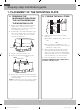
Step-by-step installation guide 1. PLACEMENT OF THE MOUNTING PLATE A. REMOVING THE MICROWAVE OVEN FROM THE CARTON/REMOVING THE MOUNTING PLATE B. FINDING THE WALL STUDS Wall WallStuds Studs 1. Remove the installation instructions, Exhaust adaptor, filters, glass tray, and the small hardware bag. Do not remove the Styrofoam protecting the front of the oven. Center Center 2. Fold back all 4 carton flaps fully against carton sides. Then carefully roll the oven and carton over onto the top side.
Step-by-step installation guide C. DETERMINING WALL PLATE LOCATION UNDER YOUR CABINET Plate position – beneath flat bottom cabinet. Plate position – beneath framed recessed cabinet bottom. 16½˝ CL At least 30˝ CL Draw a vertical line on the wall at the center of the 30˝ wide space. Tape the Rear Wall Template onto the wall matching the centerline and touching the bottom of the cabinet. 30˝ to Cooktop Draw a vertical line on the wall at the center of the 30˝ wide space.
Step-by-step installation guide D. ALIGNING THE WALL PLATE Hole HoleAA Centerline Centerline notches notches Draw VerticalLine Line on Draw a Vertical on Wall from Center Wall from Center of Top of Top Cabinet Cabinet CL Horizontal HorizontalLine Line Area E Area Line Hole B Horizontal Horizontal Line Draw aaHorizontal lineline on wall from from bottom of “Rear Draw Horizontal on wall Wall Template”. bottom of “Rear Wall Template”. CAUTION: Wear gloves to avoid cutting fingersWear on sharp edges.
Step-by-step installation guide 2. INSTALLATION TYPES (CHOOSE A, B OR C) NOTE: This microwave is shipped assembled for Outside Top Exhaust (except for non-vented models). Select the type of ventilation required for your installation and proceed to that section. This microwave oven is compatible with the following three types of ventilation: A. Outside Top Exhaust (Vertical Duct) B. Recirculating (Non-Vented Ductless) C. Outside Back Exhaust (Horizontal Duct) A. OUTSIDE TOP EXHAUST (VERTICAL DUCT) B.
Step-by-step installation guide A. OUTSIDE TOP EXHAUST (VERTICAL DUCT) INSTALLATION OVERVIEW A1. Attach Mounting Plate to Wall A2. Prepare Top Cabinet A3. Mount the Microwave Oven A4. Adjust the Exhaust Adaptor A5. Connecting Ductwork A1. ATTACH THE MOUNTING PLATE TO THE WALL NOTE: Before tightening toggle bolts and wood screw, make sure the tabs on the mounting plate touch the bottom of the cabinet when pushed flush against the wall and that the plate is properly centered under the cabinet.
Step-by-step installation guide A3. INSTALLATION PROCEDURE FOR EXHAUST ADAPTOR AND PROPER DAMPER OPERATION CHECK A4. MOUNT THE MICROWAVE OVEN Damper Blower Plate FOR EASIER INSTALLATION AND PERSONAL SAFETY, WE RECOMMEND THAT TWO PEOPLE INSTALL THIS MICROWAVE OVEN. Exhaust Adaptor Back of Microwave Oven IMPORTANT: Do not grip or use the handle during installation. Retaining Hooks • Read the instructions on the TOP CABINET TEMPLATE. • Tape it underneath the top cabinet.
Step-by-step installation guide A5. ADJUST THE EXHAUST ADAPTOR CabinetFront Front Cabinet Open the top cabinet and adjust the exhaust adaptor to connect to the house duct. Cabinet Bottom Shelf Cabinet Bottom Shelf Filler Block Filler Block Damper Back of Microwave Oven Equivalent Equivalentto Depth of of to Depth Cabinet CabinetRecess Recess Self-Aligning Screw Self-Aligning Screw MicrowaveOven Oven Top Top Microwave 4. Attach the microwave oven to the top cabinet. 5.
Step-by-step installation guide B. RECIRCULATING (NON-VENTED DUCTLESS) INSTALLATION OVERVIEW B1. Attach Mounting Plate to Wall B2. Prepare Top Cabinet B3. Adjust Blower B4. Mount Microwave Oven B5. Install Charcoal Filter B1. ATTACH THE MOUNTING PLATE TO THE WALL NOTE: Before tightening toggle bolts and wood screw, make sure the tabs on the mounting plate touch the bottom of the cabinet when pushed flush against the wall and that the plate is properly centered under the cabinet.
Step-by-step installation guide B3. ADAPTING MICROWAVE BLOWER FOR RECIRCULATION 5. Place the blower unit back into the opening. 1. Remove and save screw that holds blower plate to microwave. 2. Lift up the blower plate. Blower Retaining Screws CAUTION: Do not pull or stretch the blower unit wiring. Make sure the wires are not pinched. Back of Microwave Oven 6. Remove the metal vent fan cover on the back of the microwave by sliding it up. 7. Close the blower door.
Step-by-step installation guide B4. MOUNT THE MICROWAVE OVEN CabinetFront Front Cabinet Cabinet Bottom Shelf Cabinet Bottom Shelf Filler Block Filler Block Equivalent Equivalentto Depth of of to Depth Cabinet CabinetRecess Recess FOR EASIER INSTALLATION AND PERSONAL SAFETY, WE RECOMMEND THAT TWO PEOPLE INSTALL THIS MICROWAVE OVEN. Self-Aligning Screw Self-Aligning Screw MicrowaveOven Oven Top Top Microwave IMPORTANT: Do not grip or use the handle during installation. 4.
Step-by-step installation guide B5. INSTALLING THE CHARCOAL FILTER 1. Remove screws on top of grille using a #1 Phillips screwdriver. 2. Open the door. 3. Remove the grill. • After push left, Pull the straight off. Charcoal filter 4. Install the charocal filter. When properly installed, the wire mesh of the filter should be visible from the front. 5. Reinstall the grille and the screws. 6. Close the door. Insert mesh-side up 18 OTR_II_DE68-03587B-05_EN.
Step-by-step installation guide C. OUTSIDE BACK EXHAUST (HORIZONTAL DUCT) INSTALLATION OVERVIEW C1. Prepare Rear Wall C2. Attach Mounting Plate to Wall C3. Prepare Top Cabinet C4. Adjust Blower C5. Mount the Microwave Oven C1. PREPARING THE REAR WALL FOR OUTSIDE BACK EXHAUST You need to cut an opening in the rear wall for outside exhaust. CL • Read the instructions on the REAR WALL TEMPLATE. • Tape it to the rear wall. • Cut the opening, following the instructions of the REAR WALL TEMPLATE.
Step-by-step installation guide C3. USE TOP CABINET TEMPLATE FOR PREPARATION OF TOP CABINET C2. ATTACH THE MOUNTING PLATE TO THE WALL You need to drill holes for the top support screws, a hole large enough for the power cord to fit through, and a cutout large enough for the exhaust adaptor. Attach the plate to the wall using toggle bolts. At least one wood screw must be used to attach the plate to a wall stud. 1. Remove the toggle wings from the bolts. 2.
Step-by-step installation guide 3. Carefully pull out the blower unit. The wires will extend far enough to allow you to adjust the blower unit. 7. Replace the blower plate in the same position as before with the screw. 8. Close the blower door. Slide blower shield onto the top of the blower door opening. Secure the blower to the microwave oven using the blower retaining screws from Step 1 except the upper blower motor retaining screw.
Step-by-step installation guide C5. MOUNT THE MICROWAVE OVEN CabinetFront Front Cabinet Cabinet Bottom Shelf Cabinet Bottom Shelf Filler Block Filler Block Equivalent Equivalentto Depth of of to Depth Cabinet CabinetRecess Recess FOR EASIER INSTALLATION AND PERSONAL SAFETY, WE RECOMMEND THAT TWO PEOPLE INSTALL THIS MICROWAVE OVEN. Self-Aligning Screw Self-Aligning Screw MicrowaveOven Oven Top Top Microwave IMPORTANT: Do not grip or use the handle during installation. 4.
Before you use your microwave BEFORE YOU USE YOUR MICROWAVE 1. Make sure the microwave oven has been installed according to instructions. 2. Remove all packing material from the microwave oven. 3. Install turntable and ring in cavity. 4. Replace house fuse or turn breaker back on. 5. Plug power cord into a dedicated 20 amp electrical outlet. 6. Read the Owner’s Manual. 7. KEEP INSTALLATION INSTRUCTIONS FOR THE LOCAL INSPECTOR’S USE.
DE68-03587B-05 OTR_II_DE68-03587B-05_EN.
Consignes d'installation Four micro-ondes à hotte intégrée AVANT DE COMMENCER (Lisez attentivement l'intégralité des consignes.) IMPORTANT Conservez ces instructions pour pouvoir les remettre à l'inspecteur local en cas de passage. IMPORTANT Respectez tous les codes et règlements en vigueur. • Remarque destinée à l'installateur - N'oubliez pas de laisser ces instructions à l'utilisateur.
Table des matières Informations générales Guide d'installation étape par étape Consignes de sécurité importantes . . . . . . . . . . . 3 1. Emplacement de la plaque de fixation . . . . . . . . 8 Exigences en matière de raccordement électrique . . 3 A. Retrait du four micro-ondes du carton/Retrait de la plaque de fixation . . . . . . . . . . . . . . . . . . . 8 Système d'évacuation de la hotte . . . . . . . . . . . . 4 B. Détection des montants . .
Informations générales CONSIGNES DE SÉCURITÉ IMPORTANTES Lorsqu'une prise murale bipolaire standard est utilisée, il est très important qu'elle soit remplacée par une prise murale tripolaire correctement mise à la terre et installée par un électricien qualifié. Cet appareil nécessite une prise tripolaire reliée à la terre.
Informations générales SYSTÈME D'ÉVACUATION DE LA HOTTE REMARQUE : les deux prochaines pages ne vous concernent que si vous souhaitez utiliser un système d'évacuation de l'air vers l'extérieur. Si vous souhaitez que la circulation de l'air se fasse en circuit fermé, passez à la page 11. SYSTÈME D'ÉVACUATION PAR LE HAUT (EXEMPLE UNIQUEMENT) Le tableau suivant contient un exemple d'installation de conduits possible.
Informations générales Longueur maximale du conduit : REMARQUE : si vous devez installer des conduits, notez que la longueur totale du conduit rectangulaire de 3¼" x 10" ou du conduit circulaire de 6" de diamètre ne doit pas dépasser 140 pieds. afin de permettre à l'air de circuler, la longueur totale du conduit rectangulaire de 3¼" x 10" ou du conduit circulaire de 6" de diamètre ne doit pas dépasser 140 pieds. La ventilation extérieure nécessite un SYSTÈME D'ÉVACUATION DE LA HOTTE.
Informations générales DOMMAGES - TRANSPORT/INSTALLATION • Si l'appareil est endommagé lors du transport, retournez-le au magasin dans lequel il a été acheté afin qu'il soit réparé ou remplacé. • Si l'appareil est endommagé par l'utilisateur, sa réparation ou son remplacement lui incombe. • Si l'appareil est endommagé par l'installateur (autre que l'utilisateur), un accord devra être trouvé entre l'utilisateur et l'installateur en vue d'une réparation ou d'un remplacement.
Informations générales OUTILS NÉCESSAIRES Tournevis cruciforme n°1 et n°2 Crayon Règle ou mètre à ruban et règle plate Équerre de charpentier (facultatif) Cisailles (pour la coupe du registre si nécessaire) Ciseaux (pour la coupe du gabarit si nécessaire) Perceuse électrique avec mèches de 3/16", ½" et ⅝" Cales ou morceaux de bois, pour l'espacement du meuble haut si nécessaire (utilisé pour l'installation de meubles bas encastrés uniquement) Gants Scie (scie sauteuse, sciecloche ou scie à guichet
Guide d'installation étape par étape 1. EMPLACEMENT DE LA PLAQUE DE FIXATION A. RETRAIT DU FOUR MICRO-ONDES DU CARTON/RETRAIT DE LA PLAQUE DE FIXATION 1. 2. B. DÉTECTION DES MONTANTS Retirez les consignes d'installation, l'adaptateur du système d'évacuation, les filtres, le plateau en verre et le petit sachet contenant le matériel. Ne retirez pas la mousse de polystyrène protégeant l'avant du four. Montants Wall Studs Center Centre Pliez les 4 rabats du carton contre ses côtés.
Guide d'installation étape par étape C. DÉTERMINATION DE L'EMPLACEMENT DE LA PLAQUE MURALE SOUS LE MEUBLE Position de la plaque : sous un meuble à fond plat. Position de la plaque : sous un meuble encastré. 16½" CL CL 30" au minimum Tracez un trait vertical sur le mur du fond, au centre de l'espace de 30" de large. Fixez le gabarit du fond au mur en veillant à l'aligner sur le trait central et à toucher le fond du meuble.
Guide d'installation étape par étape D. ALIGNEMENT DE LA PLAQUE MURALE Hole TrouAA Encoches sur Centerline le trait central notches Sur le mur, tracez un trait Draw a Vertical Line on Wallenfrom Center vertical partant du centre du of Top Cabinet meuble haut CL Horizontal Line Trait horizontal AreaEE Zone Trou B B Horizontal Trait horizontal Line Hole Tracez unatrait horizontal sur le mur partant du dessous du Draw Horizontal line onenwall from « Gabarit du fond ». bottom of “Rear Wall Template”.
Guide d'installation étape par étape 2. TYPES D'INSTALLATION (A, B OU C) REMARQUE : ce micro-ondes est livré assemblé pour le système d'évacuation par le haut (hormis les modèles sans évents). Sélectionnez le système de ventilation adapté à votre installation et reportez-vous à la section correspondante. Ce four micro-ondes est compatible avec les trois systèmes de ventilation suivants : A. Système d'évacuation par le haut (Conduit Vertical) B.
Guide d'installation étape par étape A. SYSTÈME D'ÉVACUATION PAR LE HAUT (CONDUIT VERTICAL) PRÉSENTATION DE L'INSTALLATION A1. Fixation de la plaque murale A2. Préparation du meuble haut A3. Montage du four micro-ondes A4. Réglage de l'adaptateur du système d'évacuation A5. Raccordement des conduits A1.
Guide d'installation étape par étape A3. PROCÉDURE D'INSTALLATION DE L'ADAPTATEUR DU SYSTÈME D'ÉVACUATION ET CONTRÔLE DE FONCTIONNEMENT DU REGISTRE A4. MONTAGE DU FOUR MICRO-ONDES Registre Plaque du ventilateur POUR PLUS DE FACILITÉ ET DE SÉCURITÉ LORS DE L'INSTALLATION DE L'APPAREIL, DEUX PERSONNES SONT NÉCESSAIRES. Adaptateur du système d'évacuation Crochets de retenue IMPORTANT : évitez de saisir ou d'utiliser la poignée pendant l'installation.
Guide d'installation étape par étape A5. RÉGLAGE DE L'ADAPTATEUR DU SYSTÈME D'ÉVACUATION Avant du Front meuble Cabinet Fond du meuble Cabinet Bottom Shelf Filler Block Cale Ouvrez le meuble haut et réglez l'adaptateur du système d'évacuation afin de le relier au conduit de la cuisine. Registre Equivalent Équivalent à to Depth of l'enfoncement du Cabinet meuble Recess Arrière du four micro-ondes Self-Aligning Screw Vis autocentreuse Microwave Oven Top Haut du four micro-ondes 4.
Guide d'installation étape par étape B. CIRCULATION DE L'AIR EN CIRCUIT FERMÉ (SANS CONDUIT ET SANS ÉVENTS) PRÉSENTATION DE L'INSTALLATION B1. Fixation de la plaque murale B2. Préparation du meuble haut B3. Réglage du ventilateur B4. Montage du four micro-ondes B5. Installation du filtre à charbon B1.
Guide d'installation étape par étape B3. ADAPTATION DU VENTILATEUR DU FOUR MICRO-ONDES À LA CIRCULATION EN CIRCUIT FERMÉ 5. Remettez le ventilateur dans son logement. 1. Retirez et conservez la vis qui fixe la plaque du ventilateur au micro-ondes. 2. Soulevez la plaque du ventilateur. Vis de retenue du ventilateur ATTENTION : ne tirez pas sur les câbles du ventilateur. Assurezvous que les câbles n'ont pas été coincés au moment de la remise en place. 6.
Guide d'installation étape par étape B4. MONTAGE DU FOUR MICRO-ONDES Avant du Front meuble Cabinet Fond du meuble Cabinet Bottom Shelf Filler Block Cale Equivalent Équivalent à to Depth of l'enfoncement du Cabinet meuble Recess POUR PLUS DE FACILITÉ ET DE SÉCURITÉ LORS DE L'INSTALLATION DE L'APPAREIL, DEUX PERSONNES SONT NÉCESSAIRES. Self-Aligning Screw Vis autocentreuse Microwave Oven Top Haut du four micro-ondes IMPORTANT : évitez de saisir ou d'utiliser la poignée pendant l'installation. 4.
Guide d'installation étape par étape B5. INSTALLATION DU FILTRE À CHARBON 1. Retirez les vis situées sur le dessus de la grille à l'aide d'un tournevis cruciforme n°1. 2. Ouvrez la porte. 3. Retirez la grille. • Poussez sur la gauche puis tirez vers vous. Filtre à charbon 4. Installez le filtre à charbon. Lorsqu'il est correctement installé, le grillage métallique du filtre doit être visible depuis l'avant. 5. Remettez la grille et les vis en place. 6. Fermez la porte.
Guide d'installation étape par étape C. SYSTÈME D'ÉVACUATION PAR L'ARRIÈRE (CONDUIT HORIZONTAL) PRÉSENTATION DE L'INSTALLATION C1. Préparation du mur du fond C2. Fixation de la plaque murale C3. Préparation du meuble haut C4. Réglage du ventilateur C5. Montage du four micro-ondes C1. PRÉPARATION DU MUR DU FOND POUR LE SYSTÈME D'ÉVACUATION PAR L'ARRIÈRE Vous devez pratiquer une ouverture dans le mur du fond pour installer le système d'évacuation.
Guide d'installation étape par étape C3. UTILISATION DU GABARIT DU MEUBLE HAUT POUR LA PRÉPARATION DU MEUBLE HAUT C2. FIXATION DE LA PLAQUE MURALE Vous devez à présent percer les trous des vis de fixation supérieures ; leur diamètre doit permettre le passage du cordon d'alimentation et leur découpe la fixation de l'adaptateur du système d'évacuation. Fixez la plaque au mur à l'aide de boulons à ailettes. Au moins une vis à bois est nécessaire pour fixer la plaque à un montant. 1.
Guide d'installation étape par étape 3. Retirez le ventilateur avec précaution. Les câbles sortent suffisamment pour vous permettre de le régler. AVANT : ouvertures des ailettes du ventilateur dirigées vers l'avant 7. Remettez la plaque du ventilateur et la vis en place, au même emplacement que précédemment. 8. Fermez la plaque du ventilateur. Faites glisser le protecteur du ventilateur par-dessus l'ouverture de la plaque du ventilateur.
Guide d'installation étape par étape C5. MONTAGE DU FOUR MICRO-ONDES Avant du Front meuble Cabinet Fond du meuble Cabinet Bottom Shelf Filler Block Cale Equivalent Équivalent à to Depth of l'enfoncement du Cabinet meuble Recess POUR PLUS DE FACILITÉ ET DE SÉCURITÉ LORS DE L'INSTALLATION DE L'APPAREIL, DEUX PERSONNES SONT NÉCESSAIRES. Self-Aligning Screw Vis autocentreuse Microwave Oven Top Haut du four micro-ondes IMPORTANT : évitez de saisir ou d'utiliser la poignée pendant l'installation. 4.
Avant d'utiliser votre four micro-ondes AVANT D’UTILISER VOTRE FOUR MICRO-ONDES 1. Assurez-vous que le four micro-ondes a été installé conformément aux instructions. 2. Retirez tout élément d'emballage du four microondes. 3. Installez le plateau tournant et l'anneau de guidage dans le four. 4. Remplacez le fusible ou remettez le disjoncteur sous tension. 5. Branchez le cordon d'alimentation sur une prise dédiée de 20 A. 6. Lisez le manuel d'utilisation. 7.
DE68-03587B-05 OTR_II_DE68-03587B-05_CFR.