Installation Instructions Over The Range Microwave Oven BEFORE YOU BEGIN (Read these instructions completely and carefully.) IMPORTANT Save these instructions for local inspector’s use. IMPORTANT Observe all governing codes and ordinances. • Note to Installer -B e sure to leave these instructions with the Consumer. • Note to Consumer -K eep these instructions for future reference. • Skill level - I nstallation of this appliance requires basic mechanical and electrical skills.
Contents General information Step-by-step installation guide Important safety instructions. . . . . . . . . . . 3 1. Placement of the mounting plate. . . . . . 8 Electrical requirements. . . . . . . . . . . . . . . . 3 A. Removing the microwave oven from the carton/Removing the mounting plate . . . . 8 Hood exhaust. . . . . . . . . . . . . . . . . . . . . . . . 4 B. Finding the wall studs . . . . . . . . . . . . . . . . 8 Damage - Shipment/Installation . . . . . . . . 6 C.
General information IMPORTANT SAFETY INSTRUCTIONS This product requires a three-prong grounded outlet. The installer must perform a ground continuity check on the power outlet box before beginning the installation to insure that the outlet box is properly grounded. If not properly grounded, or if the outlet box does not meet electrical requirements noted (under ELECTRICAL REQUIREMENTS), a qualified electrician should be employed to correct any deficiencies.
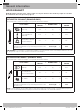
General information HOOD EXHAUST NOTE: Read these next two pages only if you plan to vent your exhaust to the outside. If you plan to recirculate the air back into the room, proceed to page 11. OUTSIDE TOP EXHAUST (EXAMPLE ONLY) The following chart contains an example of one possible ductwork installation. DUCT PIECES EQUIVALENT LENGTH x NUMBER USED = EQUIVALENT LENGTH Roof Cap 24 ft. x (1) = 24 ft. 12 Ft. Straight Duct (6˝ Round) 12 ft. x (1) = 12 ft.
General information Maximum duct length: NOTE: If you need to install ducts, note that the total duct length of 3¼˝ x 10˝ rectangular or 6˝ diameter round duct should not exceed 140 equivalent feet. For satisfactory air movement, the total duct length of 3¼˝ x 10˝ rectangular or 6˝ diameter round duct should not exceed 140 equivalent feet. Outside ventilation requires a HOOD EXHAUST DUCT. Read the following carefully. Elbows, transitions, wall and roof caps, etc.
General information DAMAGE - SHIPMENT/INSTALLATION • If the unit is damaged in shipment, return the unit to the store in which it was bought for repair or replacement. • If the unit is damaged by the customer, repair or replacement is the responsibility of the customer. • If the unit is damaged by the installer (if other than the customer), repair or replacement must be made by arrangement between the customer and installer.
General information TOOLS YOU WILL NEED #1 and #2 Phillips screwdriver Pencil Ruler or tape measure and straight edge Carpenter square (optional) Tin snips (for cutting damper, if required) Scissors (to cut template, if necessary) Electric drill with 3/16˝, ½˝ and ⅝˝ drill bits Filler blocks or scrap wood pieces, if needed for top cabinet spacing (used on recessed bottom cabinet installations only) Gloves Saw (saber, hole or keyhole) Stud finder or Hammer (optional) Safety goggles Level Duct a
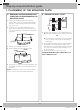
Step-by-step installation guide 1. PLACEMENT OF THE MOUNTING PLATE B. FINDING THE WALL STUDS A. REMOVING THE MICROWAVE OVEN FROM THE CARTON/REMOVING THE MOUNTING PLATE 1. Remove the installation instructions, Exhaust adaptor, filters, glass tray, and the small hardware bag. Do not remove the Styrofoam protecting the front of the oven. Wall Wall Studs Studs Center Center 2. Fold back all 4 carton flaps fully against carton sides. Then carefully roll the oven and carton over onto the top side.
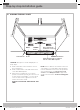
Step-by-step installation guide C. DETERMINING WALL PLATE LOCATION UNDER YOUR CABINET Plate position – beneath framed recessed cabinet bottom. Plate position – beneath flat bottom cabinet. 16 ²⁹∕₃₂˝ CL CL At least 30˝ 30˝ to Cooktop Draw a vertical line on the wall at the center of the 30˝ wide space. Tape the Rear Wall Template onto the wall matching the centerline and touching the bottom cabinet frame. Draw a vertical line on the wall at the center of the 30˝ wide space.
Step-by-step installation guide D. ALIGNING THE WALL PLATE Hole Hole AA Draw Vertical Line Draw aaVertical Line on Wall Center on Wallfrom from Center of of Top Cabinet Top Cabinet Centerline Centerline notches notches CL Horizontal HorizontalLine Line Area E E Area Line Hole Hole BB Horizontal Line Draw DrawaaHorizontal Horizontalline lineononwall wallfrom from bottom of “Rear Wall Template”. bottom of “Rear Wall Template”.
Step-by-step installation guide 2. INSTALLATION TYPES (CHOOSE A, B OR C) NOTE: This microwave is shipped assembled for Outside Top Exhaust (except for non-vented models). Select the type of ventilation required for your installation and proceed to that section. This microwave oven is compatible with the following three types of ventilation: A. Outside Top Exhaust (Vertical Duct) B. Recirculating (Non-Vented Ductless) C. Outside Back Exhaust (Horizontal Duct) A. OUTSIDE TOP EXHAUST (VERTICAL DUCT) B.
Step-by-step installation guide A. OUTSIDE TOP EXHAUST (VERTICAL DUCT) INSTALLATION OVERVIEW A1. Attach Mounting Plate to Wall A2. Prepare Top Cabinet A3. Mount the Microwave Oven A4. Adjust the Exhaust Adaptor A5. Connecting Ductwork A1. ATTACH THE MOUNTING PLATE TO THE WALL NOTE: Before tightening toggle bolts and wood screw, make sure the tabs on the mounting plate touch the bottom of the cabinet when pushed flush against the wall and that the plate is properly centered under the cabinet.
Step-by-step installation guide A3. INSTALLATION PROCEDURE FOR EXHAUST ADAPTOR AND PROPER DAMPER OPERATION CHECK 1. Lift microwave, tilt it forward, and hook slots at back bottom edge onto four lower tabs of mounting plate. Damper Blower Plate Retaining Hooks Exhaust Adaptor 2. Rotate front of oven up against cabinet bottom. Back of Microwave Oven • Read the instructions on the TOP CABINET TEMPLATE. 3. Insert a self-aligning screw through the top center cabinet hole.
Step-by-step installation guide A6. CONNECTING DUCTWORK 7. Tighten the outer two screws to the top of the microwave oven. (While tightening screws, hold the microwave oven in place against the wall and the top cabinet.) House Duct House Duct 8. Install grease filter. See the Owner’s Manual packed with the microwave. 1. Extend the house duct down to connect to the exhaust adaptor. A5. ADJUST THE EXHAUST ADAPTOR 2. Seal exhaust duct joints using duct tape.
Step-by-step installation guide B. RECIRCULATING (NON-VENTED DUCTLESS) INSTALLATION OVERVIEW B1. Attach Mounting Plate to Wall B2. Prepare Top Cabinet B3. Adjust Blower B4. Mount Microwave Oven B5. Install Charcoal Filter B1. ATTACH THE MOUNTING PLATE TO THE WALL NOTE: Before tightening toggle bolts and wood screw, make sure the tabs on the mounting plate touch the bottom of the cabinet when pushed flush against the wall and that the plate is properly centered under the cabinet.
Step-by-step installation guide B3. ADAPTING MICROWAVE BLOWER FOR RECIRCULATION 6. Remove the metal vent fan cover on the back of the microwave by sliding it up. 1. Remove and save screw that holds blower plate to microwave. 2. Lift up the blower plate. Blower Retaining Screws 7. Close the blower door. Slide blower shield onto the top of the blower door opening. Back of Microwave Oven NOTE: The exhaust adaptor with damper is not needed for recirculating models.
Step-by-step installation guide NOTE: When mounting the microwave oven, thread power cord through hole in bottom of top cabinet. Keep it tight throughout Steps 1-3. Do not pinch cord or lift oven by pulling cord. 7. Tighten the outer two screws to the top of the microwave oven. (While tightening screws, hold the microwave oven in place against the wall and the top cabinet.) 1. Lift microwave, tilt it forward, and hook slots at back bottom edge onto four lower tabs of mounting plate. 8.
Step-by-step installation guide C. OUTSIDE BACK EXHAUST (HORIZONTAL DUCT) INSTALLATION OVERVIEW C1. Prepare Rear Wall C2. Attach Mounting Plate to Wall C3. Prepare Top Cabinet C4. Adjust Blower C5. Mount the Microwave Oven C1. PREPARING THE REAR WALL FOR OUTSIDE BACK EXHAUST C2. ATTACH THE MOUNTING PLATE TO THE WALL You need to cut an opening in the rear wall for outside exhaust. Attach the plate to the wall using toggle bolts. At least one wood screw must be used to attach the plate to a wall stud. 1.
Step-by-step installation guide To use toggle bolts: C4. ADAPTING MICROWAVE BLOWER FOR OUTSIDE BACK EXHAUST Spacing for Toggles Spacing for Toggles MoreMore Than WallThickness Thickness Than Wall Mounting Mounting Plate Plate 1. Remove and save screws that hold the blower plate and the blower motor to the microwave. Toggle Wings Toggle Wings Toggle Toggle Bolt Bolt Wall Wall Blower Retaining Screws Bolt End End Bolt Back of Microwave Oven 3.
Step-by-step installation guide C5. MOUNT THE MICROWAVE OVEN 5. Rotate blower unit counterclockwise 180°. Before Rotation After Rotation Back of Microwave Back of Microwave FOR EASIER INSTALLATION AND PERSONAL SAFETY, WE RECOMMEND THAT TWO PEOPLE INSTALL THIS MICROWAVE OVEN. 6. Place the blower unit back into the opening. AFTER: Fan Blade Openings Facing Back IMPORTANT: Do not grip or use the handle during installation.
Step-by-step installation guide Cabinet Front Cabinet Front Cabinet Bottom Cabinet Bottom Shelf Shelf Filler Block Filler Block Equivalent Equivalent to to Depth of of Cabinet Depth Cabinet Recess Recess Self-Aligning ScrewScrew Self-Aligning Microwave Oven Top Top Microwave Oven 4. Attach the microwave oven to the top cabinet. 5. Insert 2 self-aligning screws through outer top cabinet holes. Turn two full turns on each screw. 6. Tighten center screw completely. 7.
Before You Use Your Microwave BEFORE YOU USE YOUR MICROWAVE 6. Read the Owner’s Manual. 1. Make sure the microwave oven has been installed according to instructions. 7. KEEP INSTALLATION INSTRUCTIONS FOR THE LOCAL INSPECTOR’S USE. 2. Remove all packing material from the microwave oven. 3. Install the turntable and ring in cavity. 4. Replace house fuse or turn breaker back on. 5. Plug power cord into a dedicated 20 amp electrical outlet.
Note 23 OTR_II_DE68-03587B-07_EN+CFR.
DE68-03587B-07 OTR_II_DE68-03587B-07_EN+CFR.
Consignes d’installation Four micro-ondes à hotte intégrée AVANT DE COMMENCER (Lisez attentivement l’intégralité des consignes.) IMPORTANT Conservez ces instructions pour pouvoir les remettre à l’inspecteur local en cas de passage. IMPORTANT Respectez tous les codes et règlements en vigueur. • Remarque destinée à l’installateur • Remarque destinée à l’utilisateur - N’oubliez pas de laisser ces instructions à l’utilisateur.
Table des matières Informations générales Guide d'installation étape par étape Consignes de sécurité importantes. . . . . . 3 1. Emplacement de la plaque de fixation . 8 Exigences en matière de raccordement électrique. . . . . . . . . . . . . . . . . . . . . . . . . . . 3 A. Retrait du four micro-ondes du carton/ Retrait de la plaque de fixation . . . . . . . . . 8 B. Détection des montants. . . . . . . . . . . . . . . 8 Système d’évacuation de la hotte. . . . . . . 4 C.
Informations générales CONSIGNES DE SÉCURITÉ IMPORTANTES Cet appareil nécessite une prise tripolaire reliée à la terre. L’installateur doit effectuer une vérification de la continuité de la mise à la terre de la prise électrique avant de commencer l’installation afin de s’assurer que la prise est correctement mise à la terre.
Informations générales SYSTÈME D’ÉVACUATION DE LA HOTTE REMARQUE : les deux prochaines pages ne vous concernent que si vous souhaitez utiliser un système d’évacuation de l’air. Si vous souhaitez que la circulation de l’air se fasse en circuit fermé, passez à la page 11. SYSTÈME D’ÉVACUATION PAR LE HAUT (EXEMPLE UNIQUEMENT) Le tableau suivant contient un type d’installation de conduits possible.
Informations générales Longueur maximale du conduit : REMARQUE : si vous devez installer des conduits, notez que la longueur totale du conduit rectangulaire de 3¼˝ x 10˝ ou du conduit circulaire de 6˝ de diamètre ne doit pas dépasser 140 pieds. afin de permettre à l’air de circuler, la longueur totale du conduit rectangulaire de 3¼˝ x 10˝ ou du conduit circulaire de 6˝ de diamètre ne doit pas dépasser 140 pieds. La ventilation extérieure nécessite un SYSTÈME D’ÉVACUATION DE LA HOTTE.
Informations générales DOMMAGES - TRANSPORT/INSTALLATION • Si l’appareil est endommagé lors du transport, retournez-le au magasin dans lequel il a été acheté afin qu’il soit réparé ou remplacé. • Si l’appareil est endommagé par l’utilisateur, sa réparation ou son remplacement lui incombe. • Si l’appareil est endommagé par l’installateur (autre que l’utilisateur), un accord devra être trouvé entre l’utilisateur et l’installateur en vue d’une réparation ou d’un remplacement.
TITÉ Informations générales OUTILS NÉCESSAIRES Tournevis cruciforme n°1 et n°2 Crayon Règle ou mètre à ruban et règle plate Équerre de charpentier (facultatif) Cisailles (pour la coupe du registre si nécessaire) Ciseaux (pour la coupe du gabarit si nécessaire) Perceuse électrique avec mèches de 3/16˝, ½˝ et ⅝˝ Cales ou morceaux de bois, pour l’espacement du meuble haut si nécessaire (utilisé pour l’installation de meubles bas encastrés uniquement) Gants Scie (scie sauteuse, sciecloche ou scie à g
Guide d’installation étape par étape 1. EMPLACEMENT DE LA PLAQUE DE FIXATION B. DÉTECTION DES MONTANTS A. RETRAIT DU FOUR MICRO-ONDES DU CARTON/RETRAIT DE LA PLAQUE DE FIXATION 1. Retirez les consignes d’installation, l’adaptateur du système d’évacuation, les filtres, le plateau en verre et le petit sachet contenant le matériel. Ne retirez pas la mousse de polystyrène protégeant l’avant du four. Montants Wall Studs Center Centre 2. Pliez les 4 rabats du carton contre ses côtés.
Guide d’installation étape par étape C. DÉTERMINATION DE L’EMPLACEMENT DE LA PLAQUE MURALE SOUS LE MEUBLE Position de la plaque : sous un meuble encastré. Position de la plaque : sous un meuble à fond plat. CL 16 ²⁹∕₃₂˝ 30˝ de la surface de cuisson Tracez un trait vertical sur le mur du fond, au centre de l’espace de 30˝ de large. Fixez le gabarit du fond au mur en veillant à l’aligner sur le trait central et à toucher le fond du cadre du meuble.
Guide d’installation étape par étape D. ALIGNEMENT DE LA PLAQUE MURALE Trou Hole AA Sur le mur, tracez un trait vertical en Draw a Vertical Line on Wall from Center du partant du centre of Top Cabinet meuble haut Encoches sur Centerline le traitnotches central CL Horizontal Line Trait horizontal Area E Zone horizontal Horizontal Line Trou Hole B B Trait Tracez trait horizontal sur le mur Draw aunHorizontal line on wall fromen partant du dessous du « Gabarit du fond ». bottom of “Rear Wall Template”.
Guide d’installation étape par étape 2. TYPES D’INSTALLATION (A, B OU C) REMARQUE : ce micro-ondes est livré assemblé pour le système d’évacuation par le haut (hormis les modèles sans évents). Sélectionnez le système de ventilation adapté à votre installation et reportez-vous à la section correspondante. Ce four micro-ondes est compatible avec les trois systèmes de ventilation suivants : A. Système d’évacuation par le haut (Conduit Vertical) B.
Guide d’installation étape par étape A. SYSTÈME D’ÉVACUATION PAR LE HAUT (CONDUIT VERTICAL) PRÉSENTATION DE L’INSTALLATION A1. Fixation de la plaque murale A2. Préparation du meuble haut A3. Montage du four micro-ondes A4. Réglage de l’adaptateur du système d’évacuation A5. Raccordement des conduits A1.
Guide d’installation étape par étape A3. PROCÉDURE D’INSTALLATION DE L’ADAPTATEUR DU SYSTÈME D’ÉVACUATION ET CONTRÔLE DE FONCTIONNEMENT DU REGISTRE 1. Soulevez le micro-ondes, inclinez-le vers l’avant et faites correspondre les encoches situées à l’arrière et en bas avec les quatre pattes inférieures de la plaque de fixation. Registre Plaque du ventilateur Adaptateur du système d’évacuation Crochets de retenue Arrière du four micro-ondes 2. Remontez le four et plaquez-le contre le plancher du meuble.
Guide d’installation étape par étape A6. RACCORDEMENT DES CONDUITS 7. Serrez les deux vis extérieures dans la partie supérieure du four micro-ondes. (Tout en serrant les vis, maintenez le four contre le mur et le meuble haut.) House Duct Conduit de la cuisine 8. Installez le filtre à graisses. Reportez-vous au manuel d’utilisation fourni avec le micro-ondes. 1. Tirez le conduit de la cuisine vers le bas pour le relier à l’adaptateur du système d’évacuation. A5.
Guide d’installation étape par étape B. CIRCULATION DE L’AIR EN CIRCUIT FERMÉ (SANS CONDUIT ET SANS ÉVENTS) PRÉSENTATION DE L’INSTALLATION B1. Fixation de la plaque murale B2. Préparation du meuble haut B3. Réglage du ventilateur B4. Montage du four micro-ondes B5. Installation du filtre à charbon B1.
Guide d’installation étape par étape B3. ADAPTATION DU VENTILATEUR DU FOUR MICRO-ONDES À LA CIRCULATION EN CIRCUIT FERMÉ ATTENTION : ne tirez pas sur les câbles du ventilateur. Assurez-vous que les câbles n’ont pas été coincés au moment de la remise en place. 1. Retirez et conservez la vis qui fixe la plaque du ventilateur au micro-ondes. 6. Retirez le couvercle métallique du ventilateur à l’arrière du micro-ondes en le glissant vers le haut. 2. Soulevez la plaque du ventilateur.
Guide d’installation étape par étape REMARQUE : nous vous recommandons d’utiliser des cales si le meuble est doté d’un débord avant en dessous du fond du meuble. 5. Insérez 2 vis autocentreuses dans les trous extérieurs du meuble haut. Tournez chaque vis de deux tours. IMPORTANT : si vous n’utilisez pas de cales, l’habillage du meuble risquerait d’être endommagé suite à un serrage trop important des vis.
Guide d’installation étape par étape C. SYSTÈME D’ÉVACUATION PAR L’ARRIÈRE (CONDUIT HORIZONTAL) PRÉSENTATION DE L’INSTALLATION C1. Préparation du mur du fond C2. Fixation de la plaque murale C3. Préparation du meuble haut C4. Réglage du ventilateur C5. Montage du four micro-ondes Utilisation des boulons à ailettes : C1.
Guide d’installation étape par étape C3. UTILISATION DU GABARIT DU MEUBLE HAUT POUR LA PRÉPARATION DU MEUBLE HAUT 3. Retirez le ventilateur avec précaution. Les câbles sortent suffisamment pour vous permettre de le régler. Vous devez à présent percer les trous des vis de fixation supérieures ; leur diamètre doit permettre le passage du cordon d’alimentation et leur découpe la fixation de l’adaptateur du système d’évacuation.
Guide d’installation étape par étape C5. MONTAGE DU FOUR MICRO-ONDE 7. Remettez la plaque du ventilateur et la vis en place, au même emplacement que précédemment. 8. Fermez la plaque du ventilateur. Faites glisser le protecteur du ventilateur par-dessus l’ouverture de la plaque du ventilateur. Fixez le ventilateur sur le four micro-ondes à l’aide des vis de retenue du ventilateur retirées à l’étape 1, à l’exception de la vis de retenue supérieure du moteur ventilateur.
Guide d’installation étape par étape 3. Insérez une vis autocentreuse dans le trou central du meuble haut. Fixez temporairement le four en faisant effectuer à la vis d’au moins deux tours complet après l’engagement des filets. (Elle sera complètement serrée ultérieurement.) Veillez à garder le cordon d’alimentation tendu. Attention à ne pas coincer le cordon, en particulier au moment où vous collez le four contre le plancher du meuble.
Avant d’utiliser votre four micro-ondes AVANT D’UTILISER VOTRE FOUR MICRO-ONDES 6. Lisez le manuel d’utilisation. 1. Assurez-vous que le four micro-ondes a été installé conformément aux instructions. 7. CONSERVEZ LES INSTRUCTIONS POUR POUVOIR LES REMETTRE À L’INSPECTEUR LOCAL EN CAS DE PASSAGE. 2. Retirez tout élément d’emballage du four microondes. 3. Installez le plateau tournant et l’anneau de guidage dans le four. 4. Remplacez le fusible ou remettez le disjoncteur sous tension. 5.
Remarque 23 OTR_II_DE68-03587B-07_EN+CFR.
DE68-03587B-07 OTR_II_DE68-03587B-07_EN+CFR.