Installation Instructions Over The Range Microwave Oven BEFORE YOU BEGIN (Read these instructions completely and carefully.) IMPORTANT Save these instructions for local inspector’s use. IMPORTANT Observe all governing codes and ordinances. • Note to Installer - Be sure to leave these instructions with the Consumer. • Note to Consumer - Keep these instructions for future reference. • Skill level - Installation of this appliance requires basic mechanical and electrical skills.
Contents General information Step-by-step installation guide Important safety instructions. . . . . . . . . . . . . . . 3 1. Placement of the mounting plate. . . . . . . . . 8 Electrical requirements. . . . . . . . . . . . . . . . . . . . . 3 A. Removing the microwave oven from the carton/Removing the mounting plate . . . . . . 8 Hood exhaust . . . . . . . . . . . . . . . . . . . . . . . . . . . . . . 4 B. Finding the wall studs . . . . . . . . . . . . . . . . . . . .
General information IMPORTANT SAFETY INSTRUCTIONS This product requires a three-prong grounded outlet. The installer must perform a ground continuity check on the power outlet box before beginning the installation to ensure that the outlet box is properly grounded. If not properly grounded, or if the outlet box does not meet electrical requirements noted (under ELECTRICAL REQUIREMENTS), a qualified electrician should be employed to correct any deficiencies.
General information HOOD EXHAUST NOTE: Read these next two pages only if you plan to vent your exhaust to the outside. If you plan to recirculate the air back into the room, proceed to page 11. OUTSIDE TOP EXHAUST (EXAMPLE ONLY) The following chart contains an example of one possible ductwork installation. DUCT PIECES EQUIVALENT LENGTH x NUMBER USED = EQUIVALENT LENGTH Roof Cap 24 ft. x (1) = 24 ft. 12 Ft. Straight Duct (6" Round) 12 ft. x (1) = 12 ft.
General information Maximum duct length: NOTE: If you need to install ducts, note that the total duct length of 3 ¼" x 10" rectangular or 6" diameter round duct should not exceed 140 equivalent feet. For satisfactory air movement, the total duct length of 3 ¼" x 10" rectangular or 6" diameter round duct should not exceed 140 equivalent feet. Outside ventilation requires a HOOD EXHAUST DUCT. Read the following carefully. Elbows, transitions, wall and roof caps, etc.
General information DAMAGE - SHIPMENT/INSTALLATION • If the unit is damaged in shipment, return the unit to the store in which it was bought for repair or replacement. • If the unit is damaged by the customer, repair or replacement is the responsibility of the customer. • If the unit is damaged by the installer (if other than the customer), repair or replacement must be made by arrangement between the customer and installer.
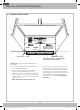
General information MOUNTING SPACE 12" max. 16 ½" 30" 5" 30" min. Bottom edge of the cabinet needs to be 30" or more from the cooking surface. Backsplash NOTES: • The space between the cabinets must be 30" wide and free of obstructions. • This microwave oven is for installation over ranges up to 36" wide. • If you are going to vent your microwave oven to the outside, see the Hood Exhaust Section for exhaust duct preparation.
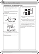
Step-by-step installation guide 1. PLACEMENT OF THE MOUNTING PLATE B. FINDING THE WALL STUDS A. REMOVING THE MICROWAVE OVEN FROM THE CARTON/REMOVING THE MOUNTING PLATE 1. Remove the installation instructions, Exhaust adaptor, filters, glass tray, and the small hardware bag. Do not remove the Styrofoam protecting the front of the oven. WallStuds Studs Wall Center Center 2. Fold back all 4 carton flaps fully against carton sides. Then carefully roll the oven and carton over onto the top side.
Step-by-step installation guide C. DETERMINING WALL PLATE LOCATION UNDER YOUR CABINET Plate position – beneath a flat bottom cabinet. 16½" CL At least 30" Plate position – beneath a framed recessed cabinet bottom. Draw a vertical line on the wall at the center of the 30" wide space. Tape the Rear Wall Template onto the wall so that the top of the template touches the bottom of the cabinet and the centerline on the template lines up with the line you drew on the wall.
Step-by-step installation guide D. ALIGNING THE WALL PLATE HoleAA Hole Draw a vertical line on the wall to mark the Draw a Vertical Line on Wallof from center theCenter cabinet of Top Cabinet above. Centerline Centerline notches notches CL Horizontal HorizontalLine Line AreaEE Area Horizontal Line Line HoleBB Horizontal Hole Draw a horizontal line on the wall along Draw a Horizontal line on wall from the bottom "RearWall Wall Template". bottomofofthe “Rear Template”.
Step-by-step installation guide 2. VENTILATION TYPES (CHOOSE A, B OR C) This microwave oven is compatible with the following three types of ventilation: NOTE: This microwave is shipped assembled for Outside Top Exhaust (except for non-vented models). An exhaust adaptor is shipped assembled and attached to the fillerupper. Select the type of ventilation required for your installation and proceed to that section. A. Outside Top Exhaust (Vertical Duct) B. Recirculating (Non-Vented Ductless) C.
Step-by-step installation guide NOTE: You must attach the house duct to the exhaust adaptor after installation is complete. A. OUTSIDE TOP EXHAUST (VERTICAL DUCT) House Duct A1. INSTALLATION PROCEDURE FOR THE EXHAUST ADAPTOR AND PROPER DAMPER OPERATION CHECK Damper Blower Plate Exhaust Adaptor Retaining Hooks Back of Microwave Oven 1. Slide the exhaust adaptor into place as shown in the diagram above. 2.
Step-by-step installation guide 3. Remove the screw that holds the blower motor and carefully pull out the blower unit. The wires will extend far enough to allow you to adjust the blower unit. 7. Close the blower door. Slide blower shield onto the top of the blower door opening. 8. Secure the blower to the microwave using the blower retaining screws from Step 1. CAUTION: To avoid breaking or cracking the blower blade, do not touch the blade.
Step-by-step installation guide C. OUTSIDE BACK EXHAUST (HORIZONTAL DUCT) C1. ADAPTING THE MICROWAVE BLOWER FOR OUTSIDE BACK EXHAUST 5. Rotate the blower unit counterclockwise 180 °. Before Rotation After Rotation 1. Remove and save screw that holds blower Plate to microwave. Blower Retaining Screws Back of Microwave Back of Microwave 6. Place the blower unit back into the opening. AFTER: Fan Blade Openings Facing Back Back of Microwave Oven End A 2.
Step-by-step installation guide 3. INSTALLATION INSTALLATION OVERVIEW A. Prepare the Rear Wall (for outside back exhaust/ horizontal duct only) B. Attach the Mounting Plate to the Wall C. Prepare the Cabinet above D. Mount the Microwave Oven E. Connect the Ductwork (for outside top exhaust/vertical duct only) A. PREPARE THE REAR WALL FOR OUTSIDE BACK EXHAUST B. ATTACH THE MOUNTING PLATE TO THE WALL You need to cut an opening in the rear wall for outside exhaust.
Step-by-step installation guide To use the toggle bolts: D. MOUNT THE MICROWAVE OVEN Spacing for Toggles More Than Wall Thickness Mounting Mounting Plate Plate Toggle Wings Toggle Wings Toggle Toggle Bolt Bolt Wall Wall FOR EASIER INSTALLATION AND PERSONAL SAFETY, WE RECOMMEND THAT TWO PEOPLE INSTALL THIS MICROWAVE OVEN. Bolt End Bolt End 3.
Step-by-step installation guide 6. Install the grease filters. See the Owner’s Manual packed with the microwave for instructions. 1. Lift the microwave, tilt it forward, and hook the slots at the back bottom edge onto the four lower tabs of the mounting plate. 2. Rotate the front of the oven up against the cabinet bottom. 3. Insert a self-aligning screw through the top center cabinet hole. Temporarily secure the oven by turning the screw at least two full turns after the threads have engaged.
Before You Use Your Microwave 4. BEFORE YOU USE YOUR MICROWAVE 6. Read the Owner’s Manual. 1. Make sure the microwave oven has been installed according to instructions. 7. Keep installation instructions for the local inspector’s use. 2. Remove all packing material from the microwave oven. 3. Install the turntable and ring in the cavity. 4. Replace the house fuse or turn the breaker back on. 5. Plug the power cord into a dedicated 15 amp electrical outlet.
Notes 19 DE68-04108A-08_IM_ME18H704SFB_AA_EN.
DE68-04108A-08 DE68-04108A-08_IM_ME18H704SFB_AA_EN.