DMS2.5(Data Management Server2.5) MIM-D01AN MIM-D01ANDZ BACnet Gateway MIM-B17BN MIM-B17BNDZ LonWorks Gateway MIM-B18BN Air Conditioner user & installation manual For more information on using the product, download the user manual from the product and refer to it. imagine the possibilities Thank you for purchasing this Samsung product. SOL_NASA_DMS2.5&BAC&LW_IBIM_EN_06095A-03.
Safety Precautions English Cautions for operation • Before using the DMS2.5, BACnet Gateway, LonWorks Gateway, read carefully these instructions. • After reading the instructions, keep this user's manual in a handy and safe place. If a user is changed, you must hand over the manuals. • Never attempt to install the air conditioning system or to move the product by yourself. WARNING CAUTION Do not attempt to install or repair the product by yourself.
Consignes de sécurité Français Précautions pour le fonctionnement • Avant d’utiliser le DMS2.5, BACnet Gateway, LonWorks Gateway, lisez attentivement ces consignes. • Après en avoir pris connaissance, conservez ce manuel d’utilisation dans un lieu sûr et à portée de main. En cas de changement d’utilisateur, vous devez remettre les manuels. • Ne tentez jamais d’installer le climatiseur ou de déplacer le produit par vous-même.
Contents Safety Precautions .............................. Before Installing the DMS2.5 ........ Accessories ............................................. Viewing the Parts ................................. Product Dimensions ............................ System Architecture ............................ Compatible Devices ............................... Installing the DMS2.5 ...................... Setting the Computer Environment. Setting the DMS2.5 ...........................
Before Installing the DMS2.5 Checks before installation 1 DMS2.5 IP Basically, only Private IP can be set to IP address. To use Public IP, you must set Enable public IP as ‘Enable’ from the menu [System Settings] [System environment setting]. - Private IP range : 10.0.0.0 ~ 10.255.255.255, 172.16.0.0 ~ 172.31.255.255, 192.168.0.0 ~ 192.168.255.255 - Public IP range: IP except for Private IP range and 127.0.0.1(localhost) D MS2.5 supports DHCP.
Accessories Make sure you have each item. Supplied items may vary depending on your country or service provider. Item DMS2.5 Adapter Power cable M4 x16 Screw Quantity 1 1 1 6 Shape User & Installation manual Cable tie 1 1 The DMS2.5 must be installed by a trained installer. Ensure the main power is turned off before installing the DMS2.5. Be sure to use adapter and power cable we provide. The shape of power cable may differ depending on the model.
Viewing the Parts Main Parts DMS2.5 Exterior LCD Display Shows current time and IP address. Various messages will be displayed depending on button input. LCD operation button There are 4 buttons(Menu, ▼(Down), ▲(Up), Set) and you can access menu and move, check the menu. LED Indicator Check 15 LED status such as Power, CPU-Alive, Ethernet-Linked/Active, COM1~5-TX/RX and Check DMS2.5 Bottom cover Unfasten 2 screws on the bottom and separate the bottom cover from DMS2.5. Then check cable connection part.
Viewing the Parts (Continued) DMS2.
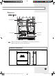
Main Parts DMS2.5 Interior Display Board 20-pin Cable Main Board 40-pin Cable Sub Board Note If you need external circuit configuration, consult with the manufacturer. Refer to page 18 for DI contact input operation. Product Dimensions 64.80 (Unit : mm) 255 240 E-9 SOL_NASA_DMS2.5&BAC&LW_IBIM_EN_06095A-03.
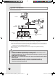
System Architecture S-NET 3 Web Client TCP/IP OnOff Controller PM 05:45 R5 485 Touch Centralized controller DMS2.5 Internet RMS Center SIM/PIM Outdoor Unit Power Meter Max 256 Indoor units (DVM Series) onnecting outdoor unit and DMS2.5. C - You can control up to 80 outdoor units and 256 indoor units by using DMS2.5. You can connect up to 16 (outdoor) units per each communication channel of the DMS2.5.
Compatible Devices No 1 2 Devices Indoor Unit Outdoor Unit Model DVM S HR, DVM S HP, DVM ECO, DVM S WATER GEO, DVM S cooling only outdoor units and indoor units that can be connected to these outdoor units OnOff controller/ Touch Centralized MCM-A202DN, MCM-A300N controller Note DVM, CAC indoor/outdoor units and ERV product groups that support NASA communication OnOff controller: Centralized controller 3 SIM MIM-B12N Needed for EHP power distribution 4 PIM MIM-B16N Needed for EHP power dist
Compatible Devices (Continued) Maximum Devices Attachable Devices Max. Note Indoor Unit 256 Tracking error occurs if exceeded The maximum number of indoor units (including ERV and MCU) that can be connected to each DMS communication channel is 128.
Installing the DMS2.5 1 Separate the installation plate on the rear side of DMS2.5. 2 Fix the installation plate on the wall using 4 screws. 3 Hang the DMS2.5 on the groove which is on the top of the installation plate. Installation plate 4 Fix the installation plate and DMS2.5 using 2 screws. Depending on the installation environment, fix DMS2.5 using assistant holes. ( Screws for assistant hole are not provided by our company.) 5 Assistant hole If you install DMS2.
Installing the DMS2.5 (Continued) Connecting Outdoor Unit 1 Unfasten the 2 screws on the bottom of the DMS2.5 front cover. Hold the bottom 2 sides of the DMS2.5 and push downwards to slide open the cover. 2 Connect the adapter to the power terminal. Arrange the adapter as the right figure. Adapter 3 Separate 1 terminal block from 5 terminal blocks that are attached to RS485 communication terminal of the DMS2.5. Then, connect outdoor unit communication cable (R1, R2)] to the terminal block.
Connecting SIM 1 Unfasten the 2 screws on the bottom of the DMS2.5 front cover. Hold the bottom 2 sides of the DMS2.5 and push downwards to slide open the cover. 2 Connect the adapter to the power terminal. Arrange the adapter as the right figure. Adapter 3 Separate 1 terminal block from 5 terminal blocks which are attached to RS485 communication terminal. Then, connect SIM/PIM communication cable to the terminal block.
Installing the DMS2.5 (Continued) Using the DI External Contact Control (Optional) Setting the External Contact Control Pattern You can set the system settings through contact control pattern. 1 Select [System Settings] menu and click [System environment setting]. 2 Click [Edit] from ‘Select the contact control pattern’. 3 Select the pattern you want to check. Pattern 1[No external input]: No operation will be made when inputting contact point control signal.
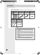
Contact control Pattern Pattern Pattern1 Control ▶ No external input (Factory default setting) When you input contact control signal in port 1, there will be no response. ▶ Level input (Emergency stop) 1. If the contact control signal is changed to ON, emergency stop status and all the indoor units are given ‘Stop’ command, and controlling using remote controller is impossible. 2. During the emergency stop, the DMS2.5 will ignore any request from the upper controllers. Pattern2 3.
Installing the DMS2.5 (Continued) DI(Digital Input) Circuitry according to Contact control Pattern P attern 2 (May be used for connection with a fire sensor) DMS2.5 Emergency Stop/Resume Operation CH1 CH2 No Connection P attern 3 (External contact signal control) DMS2.5 Operation/Stop A/C CH1 Enable/Disable remote control CH2 P attern 4 (Pulse signal control) DMS2.5 CH1 CH2 A/C Operation A/C Stop E-18 SOL_NASA_DMS2.5&BAC&LW_IBIM_EN_06095A-03.
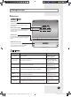
Setting the Computer Environment 1 Device related to network (Purchase separately) Computer with a LAN Card HUB or network cable(Cross·Direct cable) 2 Computer web browser specification Internet Explorer 11 or later version Silverlight 2.0 or later version Note A cross cable is used when connecting to PC directly. It is produced as transmission and reception cables are crossed. Cable 1, 2, 3, and 6 are crossed each other. Visit internet homepage (http://www.microsoft.
Setting the Computer Environment (Continued) Computer Settings for DMS2.5 Connection All settings of DMS2.5 will be arranged in web page which built in DMS2.5. You should access to DMS2.5 IP to use DMS2.5 web page. Set your computer settings as follows. DMS2.5 Factory default setting DMS2.5 IP : 192.168.0.100 IP Setting (Recommended) To access to DMS2.5 IP, set the network information of DMS2.5 connected computer as follows. IP address : 192.168.0.1(~253) Except 100 Subnet mask : 255.
Setting the DMS2.5 DMS2.5 Connection and Login Address bar 1 Click internet explorer icon( 2 When internet explorer window appears, enter IP address (https://192.168.0.100) on the address field then press [ENTER]. 1) A t initial access, security certificate warning popup message will appear as shown. This message appears since DMS2.5 used the certificate of its own, so it will not appear if DMS2.5 certificate is registered on web browser. DMS2.
Setting the DMS2.5 (Continued) 2) Registering DMS2.5 certificate on web browser A. Select ‘Content’ tap in ‘Tools’ ‘Internet options’, and click ‘Certificates’. B. Select ‘Trusted Root Certification Authorities’ and click ‘Import’. C. Click ‘Next’. E-22 SOL_NASA_DMS2.5&BAC&LW_IBIM_EN_06095A-03.
D. Select ‘Browse’ and find DMS2.5 certificate, and click ‘Next’. DMS2.5 certificate can be downloaded from [System environment setting]. E. Select ‘Place all certificates in following drive’ and click ‘Next’. F. Click ‘Finish’, and click ‘Yes’ when security warning appears. E-23 SOL_NASA_DMS2.5&BAC&LW_IBIM_EN_06095A-03.
Setting the DMS2.5 (Continued) 3 If it is the first time to access DMS2.5, “Install Microsoft Silverlight” message will appear. If Microsoft Silverlight has already been installed, the screen will not appear. 4 Click [Run] button and continue installation. After installation, access DMS2.5 again. Silverlight operates normally with Windows 7 or later version. It may not operate normally with former version of Windows. E-24 SOL_NASA_DMS2.5&BAC&LW_IBIM_EN_06095A-03.
5 5 Enter ID and password when DMS2.5 main web page appears. Then click [LOGIN]. Depending on authorization settings set by the administrator, access to some functions may be restricted. For user authorization setting, refer to System settings User authorization management. The default DMS2.5 user ID is ‘admin’ and password is ‘ac0530’. Note Only authorized users can access to web page. Connection speed may slow down. Fewer than 5 concurrent users are recommended. DMS2.
Setting the DMS2.5 (Continued) DMS2.5 System Environment Setting (Network settings) Y ou can set and check information about DMS2.5 installation operation. DMS2.5 Network Information Setting 1 Select [System Settings] menu and click [System environment setting]. 2 Click [Edit] from DMS2.5 network information window. 3 When text boxes of IP address, subnet mask address, default gateway and DNS server are enabled, enter values for each item. 15 letters can be entered for each item.
Note F actory setting is as follows. - IP address: 192.168.0.100 - Subnet mask address: 255.255.255.0 - Default gateway: 192.168.0.1 - DNS server: 0.0.0.0 If you enabled the function by checking ‘DHCP‘, you can check changed network information on the external LCD display. If ‘DHCP’ is set, IP address from DHCP server will be displayed. DMS2.5 gets automatically set IP address when you activate DHCP function. When connecting DMS2.5 to S-NET series, you can connect them using the IP.
Setting the DMS2.5 (Continued) System Time Setting 1 Select [System Settings] menu and click [System environment setting]. 2 Click [Edit] from system time setting. 3 Enter system time(year/month/day/hour/minute/second). You can enter only numbers. Year: You can enter from 1980 to 2035. Month: You can enter from 1 to 12. Day: You can enter from 1 to 31. Hour: You can enter from 0 to 23. Minute: You can enter from 0 to 59. Second: You can enter from 0 to 59.
Setting the Language 1 Select [System Settings] menu and click [System environment setting]. 2 Click [Edit] from language selection. 3 Select a language you want then click [Save]. 4 Click [OK] when “This operation needs DMS2.5 to be restarted. Do you want to apply the setting?” message appears. Click [OK] and current web browser will be closed. DMS2.5 will restart and it may take approximately 1 minute. E-29 SOL_NASA_DMS2.5&BAC&LW_IBIM_EN_06095A-03.
Setting the DMS2.5 (Continued) DMS2.5 Name Setting 1 Select [System Settings] menu and click [System environment setting]. 2 Click [Edit] from DMS2.5 name setting window. 3 Enter name of DMS2.5 when DMS2.5 name field enabled. You can use maximum 30 letters including English alphabets and special symbols. When DMS2.5 name is set, the name will be displayed on the top title bar of web browser. 4 Click [Save] after setting is completed. 5 Click [OK] when “This information will be modified.
Error Mail Forwarding Setting 1 Select [System Settings] menu and click [System environment setting]. 2 Click [Edit] from error mail forwarding setting. 3 Set all the items as the value you want when all items fields are enabled. If you select ‘Apply’, you should enter e-mail address, SMTP server ID, password, and SMTP server address. If you select ‘Not apply’, E-mail, ID, PW and SMTP server items will not affect. 4 Click [Save] after setting is completed.
Setting the DMS2.5 (Continued) Setting Enable public IP 1 Select [System Settings] menu and click [System environment setting]. 2 Click [Edit] on Enable public IP section. 3 Select whether to use Public IP or not. When you select ‘Enable’, you must register the Public IP of PCs or network devices to access DMS2.5 from the PCs or network devices. 4 Click [Save]. Setting Public IP of upper controller 1 Select [System Settings] menu and click [System environment setting].
System setting initialization 192.168.0.100 06:12:13(AM) 1 Press [Menu], [], [] or [Set] on LCD if IP and current time are displayed on LCD screen. Main menu screen appears. Initialization is not possible in the screen which time information is displayed. MAIN MENU 1.IP Config 2 Press [Menu] [] [] [] [Menu] buttons in order in main menu screen. Caution will be displayed on LCD Display. Are you sure? YES:Set, NO:Menu 3 Initialize DMS2.
Tracking What is tracking? Tracking is an operation that finds devices which are connected to DMS2.5. Through tracking operation, devices which are connected to DMS2.5 can recognize if they are connecting to DMS2.5. To supervise and control system air conditioner using DMS2.5, tracking should be done first. Things you can do through tracking Checking the number of devices installed, setting communication mode for each channel, DVM tracking, Renaming is possible through tracking.
Setting Communication Mode for Each Channel 1 Select [System Settings] menu and click [Tracking]. 2 Click [Edit] from communication mode for each channel setting. [Edit] will change to [Cancel]. Selection buttons are enabled. However, the channels which have searched device maintains its selection button disabled. 3 When each channel is enabled, check the communication mode you want to set for each channel.
Tracking (Continued) DVM Tracking 1 Select [System Settings] menu and click [Tracking]. 2 Click [DVM Tracking]. 3 Enter administrator’s password and then click [OK]. 4 Tracking information window pops up. Check it and click [OK] to continue. Execute tracking depending on the communication mode set by communication mode setting for each channel. 5 “Tracking is in progress. Please wait.” message appears. Tracking takes from few seconds to several ten minutes.
6 Tracking completed message will appear. Select Zone initialization mode you want. No initialization: No zone information initialization will be made. Individual initialization: Initialize zone information as individual mode. - I ndividual mode: Arrange by indoor unit main address on monitoring page. Group initialization: Initialize zone information as group mode. -G roup mode: Create group by indoor unit group address (RMC) on monitoring page.
Tracking (Continued) Disconnect All Devices Function Initialize searched device status in DMS2.5. Monitoring and controlling of all the connected devices to DMS2.5 will be stopped when you use this function. Connect searched device to the other channel and execute tracking. If the other device is searched in the channel you want to use, use ‘Disconnect all devices’ function. If you use this function, DMS2.5 device connection status will be initialized.
Renaming the Device 1 Select [System Settings] menu and click [Tracking]. 2 Click [Edit] on the bottom of tracking device list. [Edit] will change to [Cancel]. When the type of the device is displayed, NEW communication address will be shown with it. Note 3 If you press [Cancel] button, [Cancel] will change to [Edit], and the changed name of device will be restored to original name.
Tracking (Continued) DMS DI•DO Port Setting 1 Select [System Settings] and then click [Tracking]. 2 Click [Setting] which is next to DMS DI•DO of device list. 3 Click [Edit] which is on the bottom of DMS DI•DO setting page. [Edit] will change to [Cancel]. 4 Edit each item when DMS DI•DO selection and input fields are activated. Device type : DI or DO Short name – Input short name of the device. Full name – Input full name of the device.
PIM Setting 1 Click [System Settings] [ Tracking] when DMS2.5 web page menu screen appears. 2 Click [Setting] which is next to PIM of device list. Enter administrator’s password and then click [OK]. 3 Click [Edit] which is on the bottom of PIM setting page. [Edit] will change to [Cancel]. 4 Select a field you want to change. Meter Value ( 0~999999.9, to one decimal place) Meter Type / Pulse rate - Electricity (1~10000) - Water (1~10000) - Gas (0.
Setting the Power Distribution When doing power distribution, set SIM/PIM channel for each indoor unit. Channel Setting by Indoor Unit 1 Click [EHP Power Consumption Inspection] [Channel setting by indoor unit] when DMS2.5 web page menu screen appears. 2 Click [Edit] when the setting channel by indoor unit screen appears. 3 Check the address and channel information of SIM/PIM which is connected to watt-hour meter. I f 0~7 SIM/PIM units execute tracking, it will be displayed as 16~23 in DMS2.5.
6 Check the virtual channel information of indoor/outdoor unit. To execute power distribution without SIM/PIM, you should set virtual channel. When bringing indoor unit’s power from outdoor unit, set the ‘Outdoor unit virtual channel’ information only. ( ‘Outdoor unit virtual channel’ is referring to watt-hour meter which is connected to outdoor unit.
Appendix IP Terminology D MS2.5 needs IP address to contact other computers. 1. Public IP 1-1. Static IP 1-2. Dynamic IP 2. Private IP 2-1. Static IP 2-2. Dynamic IP 1. Public IP : Ordinary IP used to connect internet is called public IP. 1-1. Static IP : Static IP is a number that is assigned to a computer by an Internet service provider (ISP) to be its permanent address on the Internet. 1-2.
Examples of DMS2.5 Installation with DSL Local Management without External Control : Use Private IP Direct connection between DMS2.5 and computer or controller DMS2.5 Computer Cross cable Private IP : 192.168.0.100 Private IP : 192.168.0.1 (Mount separate LAN card) Direct connection between DMS2.5 and computer or controller through HUB HUB Computer DMS2.5 Private IP : 192.168.0.100 Private IP : 192.168.0.1 (Mount separate LAN card) E-45 SOL_NASA_DMS2.5&BAC&LW_IBIM_EN_06095A-03.
Appendix (Continued) Initial Connection Error (for Private IP) Several DMS2.5s are Connected to the Same Network Computer DMS2.5 ① Initial IP : 192.168.0.100 Computer cannot distinguish which DMS2.5 has 192.168.0.100 IP. DMS2.5 ② Initial IP : 192.168.0.100 DMS2.5 ③ Initial IP : 192.168.0.100 DMS2.5 ④ Initial IP : 192.168.0.100 In factory setting, all IP of DMS2.5 is same. Therefore, if you connect several DMS2.5 to the same network, the computer cannot distinguish which DMS2.5 has 192.168.0.
BACnet Gateway setting System Architecture BMS system Internet BMS Engineering SAMSUNG Engineering BACnet Gateway OnOff controller PM 05:45 Touch Centralized Controller Control & Monitoring RS 485 Schedule Settings Touch Centralized controller Outdoor Unit Max 256 Indoor units (DVM Series) Connecting outdoor units and BACnet Gateway - You can control up to 80 outdoor units and 256 indoor units using BACnet Gateway.
BACnet Gateway setting (Continued) Compatible Devices No Devices Model Note Outdoor unit: DVM S HR, DVM S HP, DVM ECO, DVM S WATER, DVM S Cooling Only Indoor unit: Models that can be connected with above outdoor units You should check that your indoor unit supports BACnet Gateway. (Refer to BACnet point list.
Maximum Devices Attachable Devices Max. Note Indoor Unit 256 Tracking error occurs if exceeded The maximum number of indoor units (including ERV and MCU) that can be connected to each communication channel is 128. OnOff controller/ Touch Centralized controller 75 Must not exceed 15 units per each RS485 communication terminal Outdoor unit 80 Must not exceed 16 units per each RS485 communication terminal SIM/PIM 8 Watt-hour Meter 64 Maximum 8 units can be connected to 1 SIM/PIM.
BACnet Gateway setting (Continued) Setting the BACnet Gateway BACnet Gateway Connection and Login 1 Click internet explorer icon( 2 When internet explorer window appears, enter IP address (https://192.168.0.100) on the address bar then press [ENTER]. 3 If it is the first time to access BACnet Gateway, “ Install Microsoft Silverlight” message will appear. If the Microsoft Silverlight has already been installed, the above message will not appear. 4 Click [Run] button and continue installation.
If you use accounts with authorization level lower than management group or accounts with general authorization level, you cannot access BACnet Gateway settings. If you cannot access BACnet Gateway, consult the manager. 6 If you login successfully, 'Control and Monitoring' screen will appear. Click [System Setting]➔[BACnet configuration] menu to switch to BACnet Gateway.
BACnet Gateway setting (Continued) Reading EHP Watt-hour Meter Setting and checking watt-hour meter 1 Click [System and Checking Watt-hour meter]. You can change settings on watt-hour meter only when SIM/PIM interface module is connected. 2 Click [Edit] from the 'Setting and checking Watt-hour meter' screen. CT proportion is set to ‘1’ as factory default value. 3 Set the [Name] and [CT proportion] for the watt-hour meter.
Monthly baseline setting 1 Click [System and Checking Watt-hour meter]. 2 Click [Edit] from the ‘Monthly baseline setting’ screen. You can make changes when list box enables. 3 Set the Monthly baseline setting. You can select from 1 ~ 31. If you select the last day of the month, it will automatically set the last day of corresponding month as baseline. Ex) Last day of February: 28th or 29th Power consumption is calculated for a month before monthly baseline.
BACnet Gateway setting (Continued) System Settings You can set and check information about BACnet Gateway installation and operation. BACnet Gateway network information 1 Click [System Settings]. 2 Click [Edit] from the ‘BACnet network information’ section. 3 When text boxes of IP, Subnet mask, Default gateway, DNS server, BBMD IP, BBMD PORT, Network No., and BACnet PORT are enabled, enter the address values for each item. 15 letters can be entered for each item.
BACnet gateway information and initialization 1 Click [System Settings]. 2 You can check the basic BACnet gateway information from 'BACnet gateway information' section. 3 Click [Edit] from the ‘BACnet gateway information’ section. 4 If you want to initialize ‘Recipient_list’, Check and click [Save]. 5 When the pop-up window appears, click [OK]. BACnet Gateway will restart and the system will initialize ‘Recipient_list’.
BACnet Gateway setting (Continued) Device Configuration Checking device information 1 Click one of the Object ID from 'Object ID' column. Detail information of the selected device will be displayed in device information. 2 Analog data of the selected device will be displayed in Analog data. Object ID: Displays ID of the corresponding object. Type: Displays type of the corresponding object.
BACnet Protocol Implementation Conformance Statement Date: 2017. 08. 31 Vendor Name: Samsung Electronics Co., Ltd. Product Name: DMS BACnet Gateway Product Model Number: MIM-B17BN, MIM-B17BNDZ Application Software Version: 1.20 Firmware Revision: 1.35 BACnet Protocol Revision: 12 Product Description: This product supports BACnet/IP and provide functions to monitor and control status of air conditionerss.
BACnet Gateway setting (Continued) SUPPORTED BIBBS AE-N-A AE-N-I-B AE-N-E-B AE-ACK-A AE-ACK-B Alarm and AE-ASUM-A Event AE-ASUM-A Management AE-ESUM-A AE-ESUM-B AE-INFO-A AE-INFO-B AE-LS-A AE-LS-B SCHED-A Scheduling SCHED-I-B SCHED-E-B T-VMT-A T-VMT-I-B T-VMT-E-B T-ATR-A T-ATR-B Trending T-VMMV-A T-VMMV-I-B T-VMMV-E-B T-AMVR-A T-AMVR-B DM-DDB-A DM-DDB-B DM-DOB-A DM-DOB-B DM-DCC-A DM-DCC-B DM-TM-A Device and DM-TM-B Network DM-TS-A Management DM-TS-B DM-UTC-A DM-UTC-B DM-RD-A DM-RD-B DM-BR-A DM-BR-B BIBB NA
SUPPORTED BIBBS DM-R-A DM-R-B DM-LM-A DM-LM-B DM-OCD-A Device and DM-OCD-B Network Management DM-VT-A DM-VT-B NM-CE-A NM-CE-B NM-RC-A NM-RC-B BIBB NAME SUPPORTED REMARKS Restart-A Restart-B List Manipulation-A List Manipulation-B Object Creation & Deletion-A Object Creation & Deletion-B Virtual Terminal-A Virtual Terminal-B Connection Establishment-A Connection Establishment-B Router Configuration-A Router Configuration-B Segmentation Capability: Segmented requests supported W
BACnet Gateway setting (Continued) Data Link Layer Options: BACnet IP, (Annex J) BACnet IP, (Annex J), Foreign Device ISO 8802-3, Ethernet (Clause 7) ANSI/ATA 878.1, 2.5 Mb. ARCNET (Clause 8) ANSI/ATA 878.
Detail Description of Object Device Following table shows regulation of device ID and they are created automatically.
BACnet Gateway setting (Continued) BACnet Point List The BACnet point list varies depending on which [BACnet point provision type] is selected in the [System Settings] menu. There are two BACnet point provision types: (1) Basic: Reflects the default points. (2) Advanced: Reflects updated points. For details, refer to the point list below. Indoor Unit [Basic] Single indoor unit has following point list.
Instance Number Object Object Type Object Name * 24 Discharge current temperature AI ** 25 AC Indoor Notify NC AC_Notify_xx_xxxxxx AC_DisCurrentTemp_xx_xxxxxx Unit Status value Inactive Active Text-1 Text-2 Text-3 Text-4 Text-5 °C(°F) When the error occurred, send event to list of destination in the recipient_list.
BACnet Gateway setting (Continued) Instance Number Object Integrated error code of both indoor ** 19 unit and outdoor unit * 20 SPI setting Object Type AI * 21 * 22 * 23 * 24 *25 *26 27 28 29 30 *31 *32 BV HumanSensor setting BV Discharge cooling set temperature AV Discharge heating set temperatrue AV Discharge current temperature AI Wind-Free BV MDS air-flow direction MV Cooling temperature upper limit AV Heating temperature lower limit AV Use of cooling temperature upper limit BV Use of heating temp
ext-5 ), bad), list of : 8) is as AHU Kit [Basic] Single AHU unit has following point list.
BACnet Gateway setting (Continued) AHU Kit [Advanced] Single AHU unit has following point list.
Instance Number 27 28 29 30 *31 *32 33 Object Cooling temperature upper limit Heating temperature lower limit Use of cooling temperature upper limit Use of heating temperature lower limit Automatic Cooling Set Temperature Automatic Heating Set Temperature AHU Notify Object Type Object Name Unit Inactive Active Text-1 Text-2 Status value Text-3 Text-4 Text-5 AV AHU_Cool_Upper_LimitTemp_xx_xxxxx °C(°F) AV AHU_Heat_Lower_LimitTemp_xx_xxxxx °C(°F) BV AHU_Cool_Upper_Limit_set_xx_xxxxx False True BV AHU_Hea
BACnet Gateway setting (Continued) EHS [Basic] Single EHS Unit has following point list.
EHS [Advanced] Single EHS Unit has following point list.
BACnet Gateway setting (Continued) Instance Number Object Type Object Object Name Unit Inactive Active Status value Text-1 Text-2 Text-3 Heating temperature lower limit AV 34 AV 36 Cooling temperature upper limit, based on water out temperature Heating temperature lower limit, based on water out temperature Hot water temperature lower limit AV EHS_WT_Heat_Lower_LimitTemp_xx_xxxxx °C(°F) 37 Use of cooling temperature upper limit BV EHS_Cool_Upper_Limit_set_xx_xxxxx False 38 Use of heati
DVM CHILLER [Basic, Advanced] Single DVM CHILLER Unit has following point list.
BACnet Gateway setting (Continued) Interface Module (Outdoor Unit) [Basic] Single Interface Module (Outdoor Unit) has following point list.
BACnet Gateway [Basic, Advanced] BACnet Gateway has following point list. Instance Control and Number Monitoring 1 All device OFF Object Type BO 2 DMS2.5 Status AI 3 BACnet error code AI 4 Gateway Notify NC Object Name Status Value ALL_OFF_xx Inactive : All devices Off 0: Normal, 8: Emergency stop, 105 : Tracking in progress, DMS2.5_Status_xx 108 : Tracking failed 109 : DMS2.
BACnet Gateway setting (Continued) Other Information Object setting when there is communication error If any communication error occurs between the air conditioner devices, the property will be set as below. 1. Reliability property will be set as COMMUNICATION_FAILURE. 2. Fault / Alarm flag of Status_Flags property will be set as TRUE. 3. Present_Value property is readable but the value is not guaranteed.
Viewing LonWorks Gateway’s Parts Main Parts LonWorks Gateway Exterior LCD Display Shows current time and IP address. Various messages will be displayed depending on button input. LCD operation button There are 4 buttons(Menu, (Down), (Up), Set) and you can access menu and move, check the menu. LED Indicator Check 15 LED status such as Power, CPU-Alive, Ethernet-Linked/Active, COM1~4-TX/RX, Lon ACK, Lon SVC and Check.
Viewing LonWorks Gateway’s Parts (Continued) LonWorks Gateway Cable Connection Part DI Terminal1 DI Terminal2 Power Terminal RS485 Communication Terminal DO Terminal3 DO Terminal4 Lon Terminal SD Card Socket Reset Button Name Cable tie groove Reserved Ethernet Terminal Description DI Terminal1 Digital Input connection terminal, Channel1~Channel5 DI Terminal2 Digital Input connection terminal, Channel6~Channel10 DO Terminal3 Digital Output connection terminal, Channel1~Channel5 DO Terminal4 D
LonWorks Gateway Interior Display Board 20-pin Cable LonWorks Board 2-pin Cable 10-pin Cable Main Board 40-pin Cable Sub Board Note If you need external circuit configuration, consult with the manufacturer. Product Dimensions 64.80 (Unit : mm) 255 240 E-77 SOL_NASA_DMS2.5&BAC&LW_IBIM_EN_06095A-03.
LonWorks Gateway setting System Architecture BMS system Internet BMS Engineering SAMSUNG Engineering LonWorks Gateway OnOff controller PM 05:45 RS 485 Touch Centralized controller Outdoor Unit Max 128 Indoor units (DVM Series) onnecting outdoor units and LonWorks Gateway C - You can control up to 80 outdoor units and 128 indoor units using LonWorks Gateway. Each communication channel of LonWorks Gateway can be connected with 16 outdoor units.
Compatible Devices No 1 2 Devices Model Note Indoor Unit Outdoor Unit DVM S HR, DVM S HP, DVM ECO, DVM S WATER, DVM S cooling only outdoor units and indoor units that can be connected to these outdoor units Check if the LonWorks Gateway supports each type of indoor units.
LonWorks Gateway setting (Continued) Maximum Devices Attachable Devices Max. Note Indoor Unit 128 Tracking error occurs if exceeded The maximum number of indoor units (including ERV and MCU) that can be connected to each communication channel is 128.
Installing the LonWorks Gateway Commision ● Commision using Service Pin To activate the Service Pin, press and hold [SET] button for more than three seconds while time is displayed in the LCD Display window of the front side of LonWorks Gateway. Press and hold the [SET] button for more than 3 seconds. When you press Service Pin, Neuron ID will be sent and [SVC] LED of the front panel will be lit up for a second.
LonWorks Gateway setting (Continued) Control and Monitoring Item ● Functional classification by a device. The functions provided can be different according to the type of the connected device.
Although the LonWorks Gateway can connect 128 units, the actual number of available items can differ according to the number of indoor units connected. When the number of indoor units is increased, the number of controllable items will be decreased; on the other hand, as the number of indoor units decreases, the controllable items increase. The functions provided can be different according to the type of the connected device. Control and Monitoring Item The maximum number of connectable indoor units.
LonWorks Gateway setting (Continued) Setting the LonWorks Gateway LonWorks Gateway Connection and Login 1 Click internet explorer icon( 2 When internet explorer window appears, enter IP address (http://192.168.0.100) on the address bar then press [ENTER]. 3 If it is the first time to access LonWorks Gateway, “ Install Microsoft Silverlight” message will appear. If the Microsoft Silverlight has already been installed, the above message will not appear.
6 If you login successfully, 'Control and Monitoring' screen of DMS2.5 will appear. Click [System Setting]➔[LonWorks configuration] menu to switch to LonWorks Gateway. If you use accounts with authorization level lower than management group or accounts with general authorization level, LonWorks configuration will not be displayed on the menu. If the LonWorks configuration menu does not appear, consult the manager.
LonWorks Gateway setting (Continued) Monthly baseline setting 1 Click [Setting and Checking Watt-hour meter]. 2 Click [Edit] from the ‘Monthly baseline setting’ screen. You can make changes when list box enables. 3 Set the Monthly baseline setting. You can select from 1~31. If you select the last day of the month, it will automatically set the last day of corresponding month as baseline.
Device Configuration Checking and changing the Object ID List of equipment connected to LonWorks can be checked when the tracking is completed. 1 Device Type, Address, Name and Object ID will appear. 2 Object IDs are assigned in order from 1 to 128 when initial tracking is executed. 3 If you want to change the Object ID, click [Edit] and change the Object ID of the applicable device. The Object ID can not be used for more than one piece of device. Object ID can be entered between 1 ~ 128.
LonWorks Gateway setting (Continued) Overview for Function Followings are the NV lists of indoor unit(ERV/AHU kit/Fresh ducts) supported by LonWorks Gateway. 1) nvi type - Data setting is allowed 2) nvo type - Data setting is not allowed Please refer to Message Definition for Setting value. 1. Indoor Unit(ERV/AHU Kit/Fresh ducts/DVM Chiller/FCU Kit) Objects No.
2. DMS system Objects No.
LonWorks Gateway setting (Continued) Network Parameter Chart Indoor/ERV/AHU kit/Fresh ducts/DVM Chiller/FCU Kit objects SSACIndoor[nn](object id = 1-128) nvoSpaceTemp SNVT_temp_p nviOnOff SNVT_switch nviApplicMode SNVT_hvac_mode nviSetPoint SNVT_temp_p nviFanStatus SNVT_switch nviERVMode SNVT_count nviFilterReset SNVT_switch nvoApplicMode SNVT_hvac_mode nvoSetPoint SNVT_temp_p nvoOnOff SNVT_switch nvoFanStatus SNVT_switch nvoERVMode SNVT_count nvoErrorCode SNVT_count nvoDeviceAlarm SNVT_state nviUserLock
DMS system objects SSACSystem(object id = 129) nvoDigitalOut[6] SNVT_switch nviDigitalOut[6] SNVT_switch nvoDigitalIn[8] SNVT_switch nviAllOff SNVT_hvac_emerg nvoSystemLock SNVT_switch nvoDMSAlarm SNVT_count nvoSystemAlarm SNVT_count Configuration Properties nciSndHrtBt nciMinOutTm nciMinDeltaTemp nciDelayStatrup E-91 SOL_NASA_DMS2.5&BAC&LW_IBIM_EN_06095A-03.
LonWorks Gateway setting (Continued) Message Definition Data for Indoor Device ● nvoSpaceTemp(11) Description SNVT Type Value and operation Indoor temperature SNVT_temp_p: Signed Long, 2 bytes Range: -10.00 °C ~ 50.
● nvoFanStatus(15), nviFanStatus(4) Description SNVT Type Value and operation Fan Speed and direction SNVT_switch: Unsigned/signed Short Auto Low Mid High Eco Turbo Auto Value 0.0 1.0 2.0 3.0 4.0 5.0 Any>5.0 State - Stop Up-Down - 0 1 ❈ Supporting modes are different according to indoor units. - Indoor unit/FCU Kit: Auto, Low, Mid, High (Turbo : Optional) - ERV : Mid, High, Turbo - AHU Kit: High * When an indoor unit operation mode is Auto or Dehumid, Fan speed is controlled as ‘Auto’.
LonWorks Gateway setting (Continued) ● nvoDeviceAlarm(18) Description SNVT Type 1. Remote control restriction status 2. Filter alert status 3. Thermo On/Off status 4.
● nvoHeatTempLock(21), nviHeatTempLock(10) Description SNVT Type Value and operation Setting/monitoring upper limit temperature and function toggle SNVT_switch: Unsigned/signed Short Operation Unlock Lock Value 16.0 ~ 30.0 16.0 ~ 30.0 State 0 1 Heat: 16.0 °C ~ 30.0 °C ● nvoEnergyConp(23) Description SNVT Type Value and operation Electric consumption value within the period SNVT_elec_kwh_I: Signed Quad, 4bytes Raw range: 0 ~ 999999 Resolution: 0.
LonWorks Gateway setting (Continued) ● nviFilterReset(6) Description SNVT Type Filter alert reset SNVT_switch: Unsigned/singed Short Value 0.0 100.0 Value and operation State 0 1 Operation No Action Filter Reset remark ● nviUserLockout(7), nvoUserLockout(22) Description SNVT Type Remote control restriction SNVT_switch: Unsigned/singed Short Value 0.0 100.0 100.
● Expansion of nvoDevListDesc desription [0] Model information Alphabet or digit Alphabet or digit Alphabet or digit Alphabet or digit Alphabet or digit Alphabet or digit Separator Underbar(_) OnOff controller address Alphabet or digit Alphabet or digit [9] Separator Period(.) [10] [11] Alphabet or digit Interface Module address Alphabet or digit [12] Separator Period(.
LonWorks Gateway setting (Continued) Data for DMS System ● nvoDigitalOut(3), nviDigitalOut(1) Description SNVT Type Digital output status on DMS SNVT_switch: Unsigned/singed Short OFF ON Value and operation Value 0.0 100.0 State 0 1 ● nvoDigitalIn(4) Description SNVT Type Digital Input status on DMS SNVT_switch: Unsigned/singed Short OFF ON Value and operation Value 0.0 100.
● nvoSystemAlarm(7) Description SNVT Type Value and operation SIM/PIM Communication Error Code SNVT_count: Unsigned Long, 2 bytes SIM/PIM Communication Error Refer to list of Error code ● nviAllOff(2) Description All indoor units turn off SNVT Type Enumeration, emerg_t Value and operation 0 : EMERG_NORMAL 4 : EMERG_SHUTDOWN E-99 SOL_NASA_DMS2.5&BAC&LW_IBIM_EN_06095A-03.
LonWorks Gateway setting (Continued) Configuration Properties ● Overview This document provides information on all configuration properties defined for LonWorks Gateway device. For the sake of simplicity, although the configuration properties are defined to UFPTSSACSystem functional block, they are shared among the members of UFPTSSACIndoor functional blocks.
Recommendations If required, set a value greater than the default update rate (currently, 10s). Any smaller value does not yield a change in the update pattern. Associate Values nvoSpaceTemp, nvoSetPoint ● Minimum Temperature Change This configuration property sets the minimum temperature change required before the associated output network variable is updated.
Specifications Items Description Exterior Size Weight Source Power INPUT Voltage OUTPUT Voltage RS-485 Ethernet SD CARD Interface DI DO Etc. Display Input method 240 X 255 X 64.8 mm ( Width X Length X Height ) 1.48 Kg DC ADAPTOR 100-240V 50/60Hz 1.0A 12V 3A 5 Channels 10/100Mbps 1 Port Option (Purchase SD card separately) 12V Digital Input 10 Channels 12V Digital Output 8 Channels Serial Port, Reset Button 16-Character X 2-Line Character LCD Menu/Up/Down/Set 4-Tact Button E-102 SOL_NASA_DMS2.
License Open Source Announcement The software included in this product contains open source software. You may obtain the complete corresponding source code for a period of three years after the last shipment of this product by sending an email to mailto:oss.request@samsung.com. It is also possible to obtain the complete corresponding source code in a physical medium such as a CD-ROM; a minimal charge will be required. The following URL http://opensource.samsung.
DB68-06095A-03 SOL_NASA_DMS2.5&BAC&LW_IBIM_EN_06095A-03.