
Security Camera User Manual

20 – 10X MINI SMART DOME CAMERA
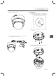
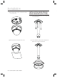
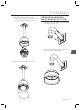
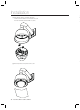
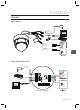
Installation
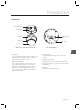
Power Connection
Please, check the voltage and current capacity of rated power carefully. Rated power is indicated in the back of
main unit.
Power Mode
Input Voltage Range
Power Consumption
C6323/ C6325 C7325
DC 12V DC 11V ~ 15V 8 W
12W
AC24V AC 20V ~ 29V 10W
21W
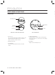
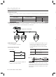
RS-485 Communication
For PTZ control, connect this line to keyboard and DVR. To control multiple cameras at the same time, RS-485
communication lines of them is connected in parallel as shown below.
❖
•
❖
•
Video Connection
Connect with BNC coaxial cable.
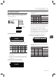
Alarm Input Connection
Sensor Input
It is noted that short circuit between GND and
Input pin means alarm activation.
❖
•
❖
•
If you want to use Alarm Input, the types of sensor
must be selected in OSD menu. The sensor types
are Normal Open and Normal. If sensor type is
not selected properly, the alarm can be activated
reversely.
Normal Open
(N.O)
Sensor output is turned ON when
sensor is activated
Normal Close
(N.C)
Sensor output is turned OFF when
sensor is activated
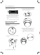
Relay Output
There are 4 Alarm Outputs and all of them are Relay
contact type. Therefore, you do not have to care about
polarity, AC/DC, and isolations between channels. Care
must be taken for the power capacity of relay contact
written above.
•
C
P
F
A
S
R
Keyboard Controller DVR
IN1
IN2
IN COM
INTERNAL
INTERNAL
Internal
Relay Out
Power
Relay Out