COLOR TELEVISION RECEIVER Chassis : Model : K15BD TK1409 TK2009 TK2009ST TK2098 CUBRE TAMBIEN MODELOS GE1400, GE2000 y GE200ST CON NUEVO CHASIS Información reservada a Agentes Autorizados BGH - Por favor conserve este Manual COLOR TELEVISION RECEIVER CONTENTS 1. Precautions 2. Specifications and IC Data 3. Disassembly and Reassembly 4. Alignment and Adjustment 5. Troubleshooting 6. Exploded View and Parts List 7. Electric Parts List 8. Block Diagram 9. PCB Layout Diagram 10. Wiring Diagram 11.
Precautions 1. Precautions Follow these safety, servicing and ESD precautions to prevent damage and protect against potential hazards such as electrical shock and X-rays. 1-1 Safety Precautions 1. Be sure that all of the built-in protective devices are replaced. Restore any missing protective shields. 2. When reinstalling the chassis and its assemblies, be sure to restore all protective devices, including: nonmetallic control knobs and compartment covers. 3.
Precautions 1-1 Safety Precautions (Continued) 9. High voltage is maintained within specified limits by close-tolerance, safety-related components and adjustments. If the high voltage exceeds the specified limits, check each of the special components. 10. Design Alteration Warning: Never alter or add to the mechanical or electrical design of this unit. Example: Do not add auxiliary audio or video connectors. Such alterations might create a safety hazard.
Precautions 1-2 Servicing Precautions Warning1: First read the “Safety Precautions” section of this manual. If some unforeseen circumstance creates a conflict between the servicing and safety precautions, always follow the safety precautions. Warning2: An electrolytic capacitor installed with the wrong polarity might explode. 1. Servicing precautions are printed on the cabinet. Follow them. 2.
Precautions 1-3 Precautions for Electrostatically Sensitive Devices (ESDs) 1. Some semiconductor (“solid state”) devices are easily damaged by static electricity. Such components are called Electrostatically Sensitive Devices (ESDs); examples include integrated circuits and some field-effect transistors. The following techniques will reduce the occurrence of component damage caused by static electricity. 2.
Specifications and IC Data 2. Specifications and IC Data 2-1 Specifications Television System 14”/20” NTSC, PAL M/N Color TV Signal Power Consumption 14” : 57 Watts Nominal, 20” : 70 Watts Nominal Picture Tube 14” : A34KQV42X 20” : A48KRD82X (H) Power Requirements AC 100 ~ 240V, 50/60Hz Operating System Remocon System (SSM - 174PT) Tuning Ranges VHF CH : 2 ~ 13 UHF CH : 14 ~ 69 CABLE CH : 1, 14~125 Antenna Input Impedance 75 ohm Unbalanced for VHF/UHF Intermediate Frequency Picture 45.
Specifications and IC Data 2-2 IC Line Up Table 2-1 IC Line-up 2-2 Loc. No Specification Description Remark IC201 TDA8841 SI NTSC, PAL M/N IC301 TDA8356 VERTICAL OUTPUT IC501 TDA6107Q RGB DRIVE AMP IC601 LA4425 SOUND-AMP (2.5W x 1CH) IC602 LA4425 SOUND-AMP (2.
Specifications and IC Data 2-3 Semiconductor Base Diagrams ELECTROLYTICCONDENSER IC DIODE TDA884X(Pin 56) SSM-174PT(Pin 42) X24CO2P(Pin 8) KS24C020(Pin 8) TRANSISTOR TRANSISTOR IC SAW-FILTER M1963M 11 1 2SD1651 2SD1650 KSD5072 KSD5071 KSD1711 KSC5386 B C E KSC815-Y KSA539-Y BC548 KTC9014 UPC574J or KA33V E B C IC TRANSISTOR TDA8133 TDA8356 TDA6107Q KA7630 KSR1012 KSR1010 KSR2010 KCT3197 E C B Fig.
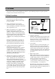
Disassembly and reassembly 3. Disassembly and Reassembly 3-1 Back Cover Removal 1. After removing the screws, press the tension rib and pull the cabinet backwards. 2. To reassemble, press the tension rib (see diagram).
Disassembly and reassembly 3-2 Main Board Removal 1. Separate the socket board from the CRT neck. 2. Remove the Anode Cap from the CRT. 3. Remove the main board by pulling it with both hands. Warning: The FBT is charged with high voltage. Before removing the Anode Cap, discharge the voltage through one of the heat sinks on the main board.
Disassembly and reassembly 3-3 Speaker Removal 1. Remove the speaker by pressing the tension rib. 1. Remove the screws. 2. Remove the speaker by pressing the tension rib.
Disassembly and reassembly 3-4 CRT Removal 1. Spread a soft mat on the floor. Place the TV set face down. 2. Remove the 4 nuts mounting the CRT to the front cabinet. Lift the CRT. 3. Caution: Because of the high vacuum and large surface area of the picture tube, be careful while handling it: (1) Always lift the picture tube by grasping it firmly around the faceplate, (2) Never lift the tube by its neck. (3) Do not scratch the picture tube or apply excessive pressure.
Alignment and Adjustments 4. Alignment and Adjustments 4-1 Preadjustment 4-1-1 Factory Mode 4-1-3 When CRT Is Replaced 1. Do not attempt these adjustments in the Video Mode. 1. Make the following adjustments AFTER setting up after setting up purity and convergence : 2. The Factory Mode adjustments are necessary when either the EEPROM (IC902) or the CRT is replaced. 3. Do not tamper with the “Adjustment” screen of the Factory Mode menu. This screen is intended only for factory use.
Alignment and Adjustments 4-2-2 Main Adjustment Parameter Table 4-1 Main Adjustment Parameter (SSM-174PT, TDA8841) OSD ABBREVIATION RANGE INITIAL DATA REMARK AUTO GAIN CONTROL AGC 0 ~ 63 STEP 05 FIX VOLTAGE CONTROL OSCILLATOR VCO 0 ~ 128 STEP 48 FIX SUB BRIGHT SBT 0 ~ 23 STEP 9 SUB CONTRAST SCT 0 ~ 23 STEP 8 RED DRIVE GAIN RG 0 ~ 63 STEP 25 GREEN DRIVE GAIN GG 0 ~ 63 STEP 25 BLUE DRIVE GAIN BG 0 ~ 63 STEP 25 PAL SUB COLOR PCR 0 ~ 23 STEP 10 FIX S-CORRECTION SC 0 ~
Alignment and Adjustments 4-2-3 Option Table 5 4 3 2 1 0 < VIDEO MUTE> 0 : VIDEO MUTE ON 1 : VIDEO MUTE OFF < BLUE-SCREEN OPTION> 0 : BLUE-BACK ON 1 : BLUE-BACK OFF 0 : AUTO SOUND OFF 1 : AUTO SOUND ON < AUTO ON OPTION > 0 : AUTO POWER ON (LAST MEMORY 1 : DISABLE (STAND-BY) < BLACK STRECTH > 0 : BLACK STRECTH ON 1 : BLACK STRECTH OFF < INITIAL LANGUAGE OPTION > 0 : PORTUGUESE 1 : SPANISH 5 4 3 2 1 0 0 0 1 1 0 :Basic Option Byte (Note : No.
Alignment and Adjustments 4-2-2 Main Adjustment Parameter Table 4-1 Main Adjustment Parameter (Z9036512PSC) FUNCTION OSD ABBREVIATION RANGE INITIAL DATA REMARK AUTO GAIN CONTROL AGC 0 ~ 63 STEP 05 SUB BRIGHT SBT 0 ~ 23 STEP 9 SUB CONTRAST SCT 0 ~ 23 STEP 8 SUB TINT STT 0 ~ 23 STEP 14 NTSC SUB COLOR NCR 0 ~ 23 STEP 00 FIX PAL SUB COLOR PCR 0 ~ 23 STEP 10 FIX RED DRIVE GAIN RG 0 ~ 63 STEP 25 GREEN DRIVE GAIN GG 0 ~ 63 STEP 25 BLUE DRIVE GAIN BG 0 ~ 63 STEP 25 SCO
4-2-3 MTS Table Table 4-2 MTS Adjustment Parameter (Z9036512PSC) FUNCTION ATENUATION OSD ABBREVIATION ATT RANGE INITIAL DATA 0 ~ 15 STEP 13 SPECTRAL SPECTRAL 0 ~ 63 STEP 46 WIDEBAND WIDEBAND 0 ~ 63 STEP 32 REMARK 4-2-4 Option Byte 0 : 51 Byte 1 : 00 4-3ST
Alignment and Adjustments 4-3 Other Adjustments 4-3-1 General 1. Usually, a color TV needs only slight touchup adjustment upon installation. Check the basic characteristics such as height, horizontal and vertical sync and focus. 2. The picture should have good black and white details. There should be no objectionable color shading; if color shading is present, perform the purity and convergence adjustments described below. 3. Use the specified test equipment or its equivalent. 4.
Alignment and Adjustments 4-3-4 FOCUS Adjustment 4-3-6 Purity Adjustment 1. Input a black and white signal. 1. Warm up the receiver for at least 20 minutes. 2. Adjust the tuning control for the clearest picture. 2. Plug in the CRT deflection yoke and tighten the clamp screw. 3. Adjust the FOCUS control for well defined scanning lines in the center area of the screen. 3. Plug the convergence yoke into the CRT and set in as shown in Fig. 4-2. 4-3-5 Cathode Voltage Adjustment (Screen Adjustment) 4.
Alignment and Adjustments 4 Pole Magnet 2 Pole Magnet 6 Pole Magnet 2 POLE PURITY Clamper Screw ADJUST THE ANG (VERTICAL LINES) YOKE CLAMP SCREW 6 POLE CONVERGENCE 4 POLE CONVERGENCE Fig. 4-2 Convergence Magnet Assembly Vertical Green Belt 31m/m Fig. 4-3 Center Convergence Adjustment 4-3-7 White Balance Adjustment (a) Set up 1 1. Warm up the TV for at least 30 minutes in the Aging Mode (OSD White). This mode is displayed by entering the following sequence: DISPLAY →FACTORY → FACTORY 2.
Alignment and Adjustments 4-3-8 Center Convergence Adjustment 1. Warm up the receiver for at least 20 minutes. 2. Adjust the two tabs of the 4 pole magnets to change the angle between them. Superimpose the red and blue vertical lines in the center area of the screen. 3. Adjust the Brightness and Contrast controls for a well defined picture. 4. Adjust the two-tab pairs of the 4 pole magnets, and change the angle between them. Superimpose the red and the blue vertical lines in the center area of the screen.
Alignment and Adjustments 4-3-10 RF AGC Adjustment Set the AGC data to 5.0 (Factory Mode). 3. Adjust with PHS/NHS (Horizontal Shift) so that the lion-head pattern and CRT centers are aligned. 4-3-11 Sub-Color Adjustment Set SCR data to 10 (Factory Mode). 4-3-12 Geometry Adjustment SC →PSL (NSL)→PVS (NVS)→ PVA (NVA) →PHS (NHS) 1. Input a lion head pattern. 2. Adjust “PVA (NVA)”, “PSL (VSL)” so that the top and bottom margirns of the screen are 4.0.
Alignment and Adjustments 4-2-3 Test Pattern (Aging Mode) 1. This mode can be used during servicing, or for confirming that the convergence and purity adjustments are correct. 2. Access the Test Pattern parameters by pressing a CHANNEL keys (s ,t) while the Service Mode is on. The cursor will move to the test pattern. Press the VOLUME keys. On-screen display: • WHITE • AGING 3.
Troubleshooting 5.
Troubleshooting 5-2 No Power Check the 125V, 13.0V B+ Lines No Check/Replace IC801, D807,D808, D809,D810,D802 Yes Check IC802 Pin 9 (5V) No Check/Replace IC802 (KA7630) Check IC901 Pin 10(4V). No Check/Replace IC901, D902 Check IC901 Pin 20 ; Stand-by : 0V Normal : 5V No Check/Replace IC901, (µ-com). Check IC201, Pin 40 (H-out) No Check/Replace IC201, Q401, Q402.
Troubleshooting 5-3 No Video (Sound OK) Check IC201 Pin 12,37 (8V) No Check/Replace IC802 KA7630 No Check/Replace IC201 Yes Check IC201 Pin 6 (CVBS) Yes Check IC201 Pins 19, 20, 21 No Check IC201 pin 27 (Y-IN) No Check/Replace IC201, Q203 No Check/Replace IC501 Yes Check IC501 on the CRT PCB Check/Replace R419, R505 (HEATER 6.
Troubleshooting 5-4 No Sound (Video OK) Check IC201 Pin 15 (Sound Out) No Check/Replace IC201 Yes Check/Replace Q902, IC601, IC602 No Check/Replace Q601, Q602, R819 No Check/Replace IC601/IC602 Yes Check IC601/IC602 Pins 1, (SOUND IN) No Check IC601/IC602 Pin 3 (B+ 10-12.5V) Yes Check IC601/IC602 Yes Check/Replace A/V Front assembly.
Exploded Views & Parts List 6.
Exploded Views & Parts List 6-2 TK2009SC/TCE 6-2 No Code No Description Specification Q’ty 1 1-1 1-2 1-3 1-4 1-5 1-6 1-7 1-8 1-9 1-10 1-11 1-12 1-13 1-14 AA92-00730B AA64-01438G AA64-00475B AA64-01338B AA64-01339B AA64-01340B AA61-60003J AA41-00227B 6006-001095 AA61-40113A AA96-00676A 6003-001026 AA64-01337B 6003-001026 6006-001095 AA97-01312A ASSY CABINET FRONT CABINET FRONT BADGE BRAND KNOB POWER WINDOW REMOCON INDICATOR LED SPRING-CS; PCB-A/V SCREW-ASS’Y TAPT STOPPER-PCB ASSY SPEAKER SCREW-TAPT
Exploded Views & Parts List 6-3 TK2009STSC/TCE No Code No 1 1-1 1-2 1-3 1-4 1-5 1-6 1-7 1-8 1-9 1-10 1-11 1-12 1-13 1-14 AA92-00730C AA64-01438H AA64-00475B AA64-01338B AA64-01339B AA64-01340B AA61-60003J AA41-00227B 6006-001095 AA61-40113A AA96-00675A 6003-001026 AA64-01337B 6003-001026 6006-001095 AA97-01336A ASSY CABINET FRONT CABINET FRONT BADGE BRAND KNOB POWER WINDOW REMOCON INDICATOR LED SPRING-CS PCB-A/V SCREW-ASS’Y TAPT STOPPER-PCB ASSY SPEAKER SCREW-TAPTITE KNOB CONTROL SCREW-TAPTITE SCREW-A
MEMO 6-4 Samsung Electronics
Electric Parts List 7. Electric Parts List 7-1 TK1409SC/TCE Loc. No. Code No. Description ; Specification Remark ASSY PCB MAIN(COM) 1 * AA97-00650D ASSY PCB MAIN(COM);TK1409SC/TCE,K15B,ARG ..2 ..2 ..2 ..2 ..2 ..2 ..2 ..2 ..2 ..2 ..2 ..2 ..2 ..2 ..2 ..2 ..2 ..2 ..2 ..2 ..2 ..2 ..2 ..2 ..2 ..2 ..2 ..2 ..2 ..2 ..2 ..2 ..2 ..2 ..2 ..2 ..2 ..2 ..2 ..2 ..2 ..2 ..2 ..2 ..2 ..2 ..2 ..2 ..2 ..2 ..2 ..2 ..2 ..2 ..2 ..2 ..2 ..2 ..2 ..2 ..2 ..2 ..
Electric Parts List Loc. No. ..2 ..2 ..2 ..2 ..2 ..2 ..2 ..2 ..2 ..2 ..2 ..2 ..2 ..2 ..2 ..2 ..2 ..2 ..2 ..2 ..2 ..2 ..2 ..2 ..2 ..2 ..2 ..2 ..2 ..2 ..2 ..2 ..2 ..2 ..2 ..2 ..2 ..2 ..2 ..2 ..2 ..2 ..2 ..2 ..2 ..2 ..2 ..2 ..2 ..2 ..2 ..2 ..2 ..2 ..2 ..2 ...3 ....4 ....4 ....4 ....4 ....4 ..2 ...3 ....4 ....4 ....4 ..2 ...3 ....4 ....4 ....4 ....4 ..2 ...3 ....4 ....
Electric Parts List Loc. No. ..2 ..2 ..2 ..2 ..2 ..2 ..2 ..2 ..2 ..2 ..2 ..2 ..2 ..2 ..2 ..2 ..2 ..2 ..2 ..2 ..2 ..2 ..2 ..2 ..2 ..2 ..2 ..2 ..2 ..2 ..2 ..2 ..2 ..2 ..2 ..2 ..2 ..2 ..2 ..2 ..2 ..2 ..2 ..2 ..2 ..2 ..2 ..2 ..2 ..2 ..2 ..2 ..2 ..2 ..2 ..2 ..2 ..2 ..2 ..2 ..2 ..2 ..2 ..2 ..2 ..2 ..2 ..2 ..2 ..2 ..2 ..2 ..2 ..2 ..2 ..2 ..
Electric Parts List Loc. No. ..2 RE02 ..2 ..2 Code No. Description ; Specification Remark 2001-001077 R-CARBON(S);150OHM,5%,1/2W,AA,TP,2.4X6.4 AA41-00227B PCB-A/V;CT-20S4,FR-1,1L,B,1.6T,245X245 0202-000187 SOLDER-WIRE FLUX;-,RS60S,D1.2,63Sn/37Pb S.N.A S.N.A * ..2 ..2 ..2 ..2 ..2 ..2 AA92-90001A ASSY-PACKING,CKD;ALL MODEL S.N.A AA69-60002A AA69-60002B AA69-60002C AA69-90001A AA61-30009A AA69-30010A S.N.A S.N.A S.N.A S.N.A S.N.A S.N.
Electric Parts List 7-2 TK2009SC/TCE Loc. No. Code No. Description ; Specification Remark ASSY PCB MAIN(COM) 1 * AA97-00650E ASSY PCB MAIN(COM);TK2009SC/TCE,K15B,ARG ..2 ..2 ..2 ..2 ..2 ..2 ..2 ..2 ..2 ..2 ..2 ..2 ..2 ..2 ..2 ..2 ..2 ..2 ..2 ..2 ..2 ..2 ..2 ..2 ..2 ..2 ..2 ..2 ..2 ..2 ..2 ..2 ..2 ..2 ..2 ..2 ..2 ..2 ..2 ..2 ..2 ..2 ..2 ..2 ..2 ..2 ..2 ..2 ..2 ..2 ..2 ..2 ..2 ..2 ..2 ..2 ..2 ..2 ..2 ..2 ..2 ..2 ..2 ..2 ..2 ..2 ..2 ..2 ..
Electric Parts List Loc. No. ..2 ..2 ..2 ..2 ..2 ..2 ..2 ..2 ..2 ..2 ..2 ..2 ..2 ..2 ..2 ..2 ..2 ..2 ..2 ..2 ..2 ..2 ..2 ..2 ..2 ..2 ..2 ..2 ..2 ..2 ..2 ..2 ..2 ..2 ..2 ..2 ..2 ..2 ..2 ..2 ..2 ..2 ..2 ..2 ..2 ..2 ...3 ....4 ....4 ....4 ....4 ....4 ..2 ...3 ....4 ....4 ....4 ..2 ...3 ....4 ....4 ....4 ....4 ..2 ...3 ....4 ....4 ....4 ....4 ..2 ..2 ..2 ..2 ..2 ..2 ..2 ..
Electric Parts List Loc. No. ..2 ..2 ..2 ..2 ..2 ..2 ..2 ..2 ..2 ..2 ..2 ..2 ..2 ..2 ..2 ..2 ..2 ..2 ..2 ..2 ..2 ..2 ..2 ..2 ..2 ..2 ..2 ..2 ..2 ..2 ..2 ..2 ..2 ..2 ..2 ..2 ..2 ..2 ..2 ..2 ..2 ..2 ..2 ..2 ..2 ..2 ..2 ..2 ..2 ..2 ..2 ..2 ..2 ..2 ..2 ..2 ..2 ..2 ..2 ..2 ..2 ..2 ..2 ..2 ..2 ..2 ..2 ..2 ..2 ..2 ..2 ..2 ..2 ..2 ..2 ..2 ..
Electric Parts List Loc. No. ..2 ..2 ..2 ..2 ..2 ..2 Code No. Description ; Specification AA69-60002B AA69-60002C AA69-90001A AA61-30009A AA63-10007C AA69-30010A Remark WOODEN-BOX;WOOD,1060,560,400,45%,WOODEN-BOX;WOOD,530,560,400,45%,SILICAGEL;M2,5GR,-,-,LOCKER-BAND,CLIP;-,SPC-1,-,-,18MM T0.5,BAND-PP;-,-,-,W18,-,CLEAR,1G,BAG-SHEET;LDPE,T0.08,W220,L300,-,-,- S.N.A S.N.A S.N.A S.N.A S.N.A S.N.A Loc. No. * ..2 * S.N.A 0202-000187 SOLDER-WIRE FLUX;-,RS60S,D1.2,63Sn/37Pb S.N.
Electric Parts List 7-3 TK2009STSC/TCE Loc. No. Code No. Description ; Specification Remark ASSY PCB MAIN(COM) 1 * AA97-00650F ASSY PCB MAIN(COM);TK2009STSC/TCE,K15B,A ..2 ..2 ..2 ..2 ..2 ..2 ..2 ..2 ..2 ..2 ..2 ..2 ..2 ..2 ..2 ..2 ..2 ..2 ..2 ..2 ..2 ..2 ..2 ..2 ..2 ..2 ..2 ..2 ..2 ..2 ..2 ..2 ..2 ..2 ..2 ..2 ..2 ..2 ..2 ..2 ..2 ..2 ..2 ..2 ..2 ..2 ..2 ..2 ..2 ..2 ..2 ..2 ..2 ..2 ..2 ..2 ..2 ..2 ..2 ..2 ..2 ..2 ..2 ..2 ..2 ..2 ..2 ..
Electric Parts List Loc. No. ..2 ..2 ..2 ..2 ..2 ..2 ..2 ..2 ..2 ..2 ..2 ...3 ...3 ...3 ..2 ..2 ..2 ..2 ..2 ..2 ..2 ..2 ..2 ..2 ..2 ..2 ..2 ..2 ..2 ..2 ..2 ..2 ..2 ..2 ..2 ..2 ..2 ..2 ..2 ..2 ..2 ..2 ..2 ..2 ..2 ..2 ..2 ..2 ..2 ..2 ..2 ..2 ..2 ..2 ..2 ..2 ..2 ..2 ..2 ..2 ..2 ..2 ..2 ...3 ....4 ....4 ....4 ....4 ....4 ..2 ...3 ....4 ....4 ....4 ..2 ...3 ....
Electric Parts List Loc. No. ..2 ..2 ..2 ..2 ..2 ..2 ..2 ..2 ..2 ..2 ..2 ..2 ..2 ..2 ..2 ..2 ..2 ..2 ..2 ..2 ..2 ..2 ..2 ..2 ..2 ..2 ..2 ..2 ..2 ..2 ..2 ..2 ..2 ..2 ..2 ..2 ..2 ..2 ..2 ..2 ..2 ..2 ..2 ..2 ..2 ..2 ..2 ..2 ..2 ..2 ..2 ..2 ..2 ..2 ..2 ..2 ..2 ..2 ..2 ..2 ..2 ..2 ..2 ..2 ..2 ..2 ..2 ..2 ..2 ..2 ..2 ..2 ..2 ..2 ..2 ..2 ..
Electric Parts List Loc. No. ..2 ..2 ..2 ..2 ..2 ..2 ..2 ..2 ..2 ..2 ..2 VX801S X203 X901 XC01 XC02 Z201 Z601 Code No. Description ; Specification 1405-000152 2801-003298 2801-003224 2801-003300 2801-003299 2903-001022 2903-000135 AA41-10955D AA65-30009A AA65-30104C AA65-30109A Remark VARISTOR;560V,2500A,14x8.5mm,TP CRYSTAL-UNIT;3.579545MHz,30ppm,28-AAM,20 CRYSTAL-UNIT;32.768KHZ,20PPM,28-AAY,12.5 CRYSTAL-UNIT;3.575611MHz,30ppm,28-AAM,20 CRYSTAL-UNIT;3.582056MHz,30ppm,28-AAM,20 FILTER-CERAMIC;BR,4.
Electric Parts List Loc. No. ..2 ..2 Code No. Description ; Specification Remark Loc. No. Code No. Description ; Specification Remark 3001-000274 SPEAKER;5W,8ohm,90dB,160Hz AA39-20505M LEAD CONNECTOR-ASSY;,4P,YSH025-04,REC,35 ASSY CRT 1 * ..2 ..2 ..2 ..2 AA97-00338B ASSY CRT;AA03-10029X,0mG,A48KRD82X(H),B S.N.A AA63-60028A SPACER-DY;-,NEOPRENE,-,-,-,BLK,-,-,V0 W1 AA27-50004W DEFLECTION-YOKE;-,DSE-1992LL(1H),PCL,A48 AA27-00002A MAGNET-CONVERGENCE;-,JH291-SC-OB,29.
MEMO 7-14 Samsung Electronics
Wiring Diagram 10.
11.
11-2 MAIN 2/4 TP07 TP18 TP06 TP08 TP05 TP09 TP17 TP10 TP13 TP15 TP12 TP11 TP14 TP16 11-2
11-3 MAIN 3/4 TP25 TP26 TP22 TP20 TP23 TP21 TP24 11-3
11-4 MAIN 4/4 TP27 11-4 TP28 TP29
11-5 STEREO 11-5
Waveforms 12. K15B Waveforms TP01 MICOM #31 X-TAL IN 2.9Vpp TP04 Sound-Amp IC #4 Variable 0 ~ 12 Vpp TP07 IC201 #47 Vertical drive output 1.5Vpp TP10 IC201 #7 Serial clock 5Vpp TP02 MICOM #27 Vertical SYNC 5Vpp TP05 IC201 #55 Audio deemphasis 700mVpp TP08 IC201 #41 Flyback input 6Vpp TP11 IC201 #8 Serial data input/output 5Vpp TP03 MICOM #26 Horizontal SYNC 5Vpp TP06 IC201 #51 Vertical sawtooth capacitor 3Vpp TP9 IC201 #38 CVBS-1 output 1.
Waveforms TP13 IC201 #18 Black-current input 2.5Vpp TP 16 IC201 #21 Red output 1.8Vpp TP 19 Vertical IC #4(out) 11Vpp TP 22 FBT(heater) 28Vpp 12-2 TP14 IC201 #19 Blue output 1.6Vpp TP15 IC201 #20 Green output 1.7Vpp TP 17 IC201 #28 Luminance output 1.
Waveforms TP25 SMPS IC #1(Drain) 630Vpp TP 28 Video-AMP #8(Red) 110Vpp TP26 SMPS IC #5(SYNC) 2.
MAY.