SYSTEM AIR CONDITIONER INDOOR UNIT Model : AC052FBMDEH/EU AC071FBMDEH/EU AC090FBMDEH/EU AC100FBMDEH/EU AIR CONDITIONER OUTDOOR UNIT AC052FCADEH/EU AC071FCADEH/EU AC090FCADEH/EU AC100FCADEH/EU AC100FCADGH/EU CONTENTS 1. Precautions 2. Product Specifications AC052FBMDEH/EU,AC071FBMDEH/EU, AC090FBMDEH/EU,AC100FBMDEH/EU 3. Disassembly and Reassembly 4. Troubleshooting 5. PCB Diagram AC071FCADEH/EU 6. Wiring Diagram 7. Schematic Diagram 8.
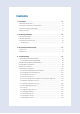
Contents 11. Precautions ........................................................................................................................................ 1-1 1-1 Precautions for the Service .............................................................................................................. 1-1 1-2 Precautions related to static electricity and PL ............................................................................ 1-1 1-3 Precautions related to product safety ...................
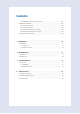
Contents 4-5-15 DC Link Over voltage/ Low voltage error ........................................................................ 4-25 4-6 PCB Inspection Method ................................................................................................................... 4-26 4-6-1 Pre-inspection Notices ........................................................................................................... 4-26 4-6-2 Inspection Procedure .............................................................
1. Precautions 1-1 Precautions for the Service O Use the standard parts when replacing the electric parts. – Confirm the model name, rated voltage, rated current of the electric parts. O When repairing the equipment, connection of the harness parts must be firm and solid. – A loose connection may cause noise or other malfunction. O When assembling and disassembling the equipment while it is laid down, lay it on soft cloth. – Otherwise it may scratch the back of the exterior of the product.
1-3 Precautions related to product safety O Do not pull the power cord and do not touch the power plug or aux power switch with wet hands. – It might cause electric shock or fire. O A damaged power line or power plug must be replaced to prevent danger. O Do not bend the power cable with excessive force, and do not place a heavy weight on the case as it might damage the cable. – It might cause electric shock or fire. O Do not use multiple electric outlets. – This might cause electric shock or fire.
2. Product Specifications 2-1 The Feature of Product Q Built-in Cassette Type After installed, the air conditioner can be harmonized with a room interior. Q High Performance & Energy Saving With the advanced BLDC inverter technology, it makes a room cool with highly energy saving and arises the efficiency of air conditioner. Q Long Piping(Length & Height) It can give the benefit to the installers and aries the reliability of the air conditioner.
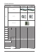
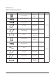
2-2 Product Specifications AC052FBMDEH/EU AC052FCADEH/EU ITEM AC071FBMDEH/EU AC071FCADEH/EU Indoor Unit Outdoor Unit IMAGE Remote Controller Power Specifications Indoor 1Φ, 220~240V,50Hz WxHxD mm 900x260x480 1150x480x260 WxHxD Size Outdoor mm 750x548x285 880x310x798 Indoor Unit kg 28.0 31.5 Outdoor Unit kg 38.5 55.0 Weight Cooling(STD) W 5000 7100 Heating(STD) W 6000 8000 Cooling(STD) W 1560 2210 Heating(STD) W 1660 2220 Cooling(STD) A 7.5 10.
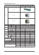
Product Specifications (cont.) AC090FBMDEH/EU AC090FCADEH/EU ITEM AC100FBMDEH/EU AC100FCADEH/EU AC100FBMDEH/EU AC100FCADGH/EU Indoor Unit Outdoor Unit IMAGE Remote Controller Power Specifications 1Φ, 220~240V,50Hz 3Φ,380~415V,50Hz Indoor WxHxD mm 1150x480x320 Outdoor WxHxD mm 940x330x998 Indoor Unit kg 35.0 Outdoor Unit kg 72.0 Size Weight Cooling(STD) W 9000 10000 Heating(STD) W 10000 11200 Cooling(STD) W 2800 3215 Heating(STD) W 2770 Cooling(STD) A 13.0 15.2 5.
2-3 Specifications of optional items 2-3-1 Accessories Item Descriptions Code-No.
Accessories (cont.) ■ Receiver & display unit & Wire kit Item Descriptions Code-No.
Accessories (cont.) ■ Wireless remote controller Item 2-6 Descriptions Code-No.
Accessories (cont.) ■ Centralized controller Item Descriptions Code-No.
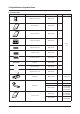
Accessories (cont.) ■ Function controller Item Descriptions Code-No. Q'TY Function controller DB97-01077A (MCM-A100) 1 Cable tie DB65-10088B 2 Cable clamp DB65-10074E 6 Remark Optional M4x16 Tapped Screw 6002-000474 7 User’s manual DB98-27317A 1 Installation manual DB98-27315A 1 Descriptions Code-No.
Accessories (cont.) ■ DMS(Date Management Server) Item Samsung Electronics Descriptions Code-No.
3.
3-1 Indoor unit No Parts 1 Blower & Motor Procedure Remark 1) After disassembling 16 places indicating screws, detach Ass'y Cabi Bottom Blower. (Use +Screw Driver) 2) Detach the Motor Fan connector from the BLDC PCB. 3) After disassembling 2 places indicating screws, detach the 2 Fan Case.
No Parts Procedure Remark 4) After disassembling 2 places indicating screws, detach Fan Motor and Blower from the set. 2 Control In 1) After disassembling 3 Indicating screw, detach the Cover control. (Use +Screw Driver) 2) Detach the Motor-Fan and Sensor Connector from the PCB.
No Parts Procedure Remark 3) Disassemble 4 indicating screws and detach Control In from the set. 3 Drain Pan Work is possible when Disassembling the Ass'y Cabi Bottom Blower. 1) Disassemble 7 indicating screws and detach Ass'y Cabi Bottom Drain..
No Parts Procedure Remark 1) Disassemble 4 indicating screws and detach the Drain Pan. (Use +Screw Driver) (2 screws each at left and right side). 4 Evap Work is possible when Disassembling the Ass'y Drain Pan. 1) Disassemble 5 indicating screws to detach Cover Pipe.
No Parts Procedure Remark 2) Disassemble Sensor on the Evap. 3) Disassemble 4 indicating screws which are in the near of Hanger Plate to detach the Evap. (Use +Screw Driver) (2 screws each at left and right side) It needs 2 peoples..
3-2 Outdoor Unit Q AC052FCADEH/EU No Parts Procedure 1 common work 1) loosen 1 pcs screw of cover control,and detach it. Remark 2) loosen 5 pcs screws on both right and left cabniet side edges and to detach the cover-top 3) Loosen 7 screwsfixed to disassemble cabi-front , and detach it.
No Parts common work Procedure Remark 4) loosen 7 screws to disassemble the cabiright ,and detach it. 5) loosen 2 screws to disassemble steel-bar. 6) loosen 3 screws to disassemble cabi-left.
No Parts Procedure 2 fan&motor 1) loosen 1 screw as indication and detached the fan. Remark 2) loosen 4 pcs motor screws and disconnect the wire betwwen assy control out and motor. 3) loosen 2 pcs bracket-motor screw and detach it.
No Parts 3 assy control out 1) lossen fixing 1 screw from cover -control 2) detach several connections from assy control out, take out assy control out. 4 Heat exchanger 1) Release the refrigerant at first 2) Looosen fixing screw on both side. 3) disaessembly the pipes in both inlet and outlet with welding torch. 4) detach the heat exchanger.
No Parts 5 compressor Procedure Remark 1) disconnect the compressor lead wire . 2)disassembly the felt comp sound.
Q AC071FCADEH/EU No Parts Procedure 1 Common Work 1) Loosen 1 fixing screw of the Cover-Control and detach the Cover Control. Remark 2) Loosen each 7 fixing screws and detach the Cabinet Upper.
No Parts Procedure Remark 3) Loosen 2 screws fixed to assemble Control Box with Cabinet-Side RH. 4) Loosen fixing screws and detach the Cabinet-Side RH. 5) Loosen 2 screws fixed on the Guide Condenser.
No Parts Procedure Remark 6) Loosen fixing screws of the Cabinet Front.
No Parts 2 Fan & Motor Procedure Remark 1) Detach the Nut Flange like the picture on the right side. (Turn counter clockwise because the screw is right-handed.) 2) Detach the Fan Propeller. 3) Loosen 4 fixing screws to detach the Motor. 4) Disconnect the wire between ASS'Y Control Out and Motor. 5) Loosen 2 fixing bolts and detach the Bracket Motor.
No Parts Procedure 3 ASS'Y Control Out 1) Detach several connectors from the ASS'Y Control Out. 2) Detach several connectors from the PCB of ASS'Y Control Out. 3) Pull up the ASS'Y Control Out. 4 Heat Exchanger 1) Release the refrigerant at first. 2) Loosen fixing screw on both sides. 3) Disassemble the pipes in both inlet and outlet with welding torch. 4) Detach the Heat Exchanger. Remark 5) Loosen 4 bolts fixed to assemble Valve Service with Bracket Valve like the picture on the right side.
No Parts 5 Compressor Procedure Remark 1) Loosen the fixing nut and detach the Compressor Lead Wire. 2) Disassemble the Felt Compressor Sound. 3) Loosen the 3 bolts at the bottom of Compressor like the picture on the right side.
N AC090FCADEH/EU AC100FCADEH/EU AC100FCADGH/EU No Parts 1 Cabi Front RH Procedure Remark You must turn off the Power before disassembly. 1) Unscrew and remove two mounting screw in the Cabinet Front RH. (Use +Screw Driver) 2 Cabi Top 3 Cabi Install Front Samsung Electronics 1) Unscrew and remove 9 screws on each side of the Cabinet-Top. (Use +Screw Driver) 1) Unscrew and remove 1 screw in the Cabinet-Install Front.
No Parts 4 Guard Cond Procedure Remark 1) Pull the sensor from Guard Cond. 2) Unscrew and remove 4 screws in the Guard Cond. (Use +Screw Driver) 5 Cabi Back RH 1) Pull the sensor from Cabi Back RH. 2) Unscrew and remove 4 screws on each side of the Cabinet Back RH.
No Parts 6 Cabi Install Back 7 Cabi Front LF Samsung Electronics Procedure Remark 1) Unscrew and remove 1 screw in the Cabinet-Install Back. (Use +Screw Driver) 1) Unscrew and remove 10 screws in the Cabinet-Front LF.
No Parts 8 Fan 3-21 Procedure Remark 1) Turn 2 mounting nuts as shown in the picture and remove it.
No Parts Procedure 9 Motor 1) Separate the Fan Propeller. 2) Unscrew and remove the 4 Motor mounting screws. (Use +Screw Driver) Remark 3) Disconnect the Motor wire From Ass'y Control Out. 10 Bracket Motor Samsung Electronics 1) Unscrew and remove 2 mounting screws in Bracket Motor.
No Parts 11 Control Out Procedure Remark 1) Disconnect 4 Connecters From Ass'y Control Out. 2) Unscrew and remove 1 mounting screw in Control Out. (Use +Screw Driver) 3) Separate Ass'y Control Out.
No Parts 12 Ass'y 4way Valve Procedure Remark 1) Purge the Coolant first. 2) Unscrew and remove 2mounting screws in muffler. 3) Unscrew and remove 2 mounting screws in Service Valve. (Use +Screw Driver) 4) Separate the pipe from the Entrance/Exit using a welder. When removing the compressor, Heat Exchanger, and Pipe, purge the Coolant inside the Compressor completely and remove the pipe with a welding flame.
No Parts 13 Ass;y EEV Valve Procedure Remark 1) Unscrew and remove 2 mounting screws in Service Valve. (Use +Screw Driver) 2) Separate the pipe from the Entrance/Exit using a welder. 14 Compressor 1) Unscrew and remove 1 mounting nut in Cover Terminal. (Use Adjustable Wrench) 2) Separate the Compressor Felt Sound.
No Parts Procedure Remark 3) As shown in the picture, unscrew and remove 3 mounting screws from the bottom. (Use Adjustable Wrench) 15 Cond Out 1) Unscrew and remove 3 screws on each side of the Assy Cond Out. (Use +Screw Driver) 2) Separate the Compressor Felt Sound.
4. Troubleshooting 4-1 Indoor Display Error and Check Method ■ Error detection and reoperation ▶ If error occurs during the operation, badness is indicated by LED flickering and all operation is stopped except LED. ▶ When reoperating by remote control and switch determine the error mode after normal operation.
4-1-1 Wired Remocon Error Display(COM2) •If an error occurs, is displayed on the wired remote controller. If you would like to see an error code, press the Test button. Display Explanation Remark Indoor unit Communication Error Indoor/Outdoor unit Communication Time Out Error 60 Packet Over data Indoor unit is not connected Communication Error Communication Error between Outdoor Main and Inverter Micom (Occurred after 1 minute detection in Main and Inverter) Indoor Temp.
4-2 Outdoor LED Error Display and Check Method No. LED Display Explanation Error Code Yellow Green Red 1 | | | Power off/ VDD NG 2 | | IPM Over Current(O.
4-3 Setting Option Setup Method Setting an indoor unit option code Model Option code AC052FBMDEH 011014-19626E-27343C-370010 Model AC100FBMDEH AC052FCADEH AC100FCADEH AC071FBMDEH AC100FBMDEH AC071FCADEH AC090FBMDEH AC090FCADEH 011017-1563A2-274750-370010 Option code 011034-15617C-276470-370000 AC100FCADGH 011034-15617C-275A64-350000 In order to set the indoor unit option code using the wired remote controller, hold down the and buttons at the same time for 5 seconds.
Set the indoor unit address and installation option with remote controller option. Set the each option separately since you cannot set the ADDRESS setting and indoor unit installation setting option at the same time.You need to set twice when setting indoor unit address and installation option. Setting an indoor unit address In order to check and set the indoor unit Main/Group Address using the wired remote controller, hold down the 1 2 and buttons at the same time for 5 seconds.
Setting an indoor unit installation option In order to check and set the indoor unit DIP option code using the wired remote controller, hold down the and buttons at the same time for 5 seconds. 1 The menu will display . button until Press the is displayed. 2 Press the button. The current DIP option code set in an indoor unit will be displayed. Page number DIP OPTION CODE 3 Press button and change the page number. The total option codes are 24digits.
Option No.
Setting an indoor unit option code Model SEG1 SEG2 SEG3 SEG4 SEG5 0 1 1 0 1 AC052FBMDEH 0 1 1 0 1 AC052FCADEH 0 1 1 0 1 AC071FBMDEH 0 1 1 0 1 AC071FCADEH 0 1 1 0 3 AC090FBMDEH 0 1 1 0 3 AC090FCADEH 0 1 1 0 3 AC100FBMDEH 0 1 1 0 3 AC100FCADEH 0 1 1 0 3 AC100FBMDEH 0 1 1 0 3 AC100FCADGH Model SEG13 SEG14 SEG15 SEG16 SEG17 2 7 3 4 3 AC052FBMDEH 2 7 3 4 3 AC052FCADEH 2 7 4 7 5 AC071FBMDEH 2 7 4 7 5 AC071FCADEH 2 7 5 A 6 AC090FBMDEH 2 7 5 A 6 AC090FCADEH 2 7 6 4 7 AC100FBMDEH 2 7 6 4 7 AC100FCADEH 2 7 6 4 7 AC10
4-4 Iterms to be checked first 1. The input voltage should be rating voltage ±10% range. The air conditioner may not operate properly if the voltage is out of this range. 2. Is the link cable linking the indoor unit and the outdoor unit linked properly? The indoor unit and the outdoor unit shall be linked by 4 cables. Check the terminals if the indoor unit and outdoor unit are properly linked by the same number of cables. Otherwise the air conditioner may not operate properly. 3.
4-5 Fault Diagnosis by Symptom 4-5-1 No Power(completely dead) - Initial diagnosis 1. Checklist : 1) Is Power source voltage normal? 2) Is AC power linked correctly? ( miss-wiring, wire detaching etc. ) 3) Is any LED on the MAIN PCB of Outdoor unit lit? 4) Is terminal voltage for indoor unit normal? (230Vac nominal) 5) Is Wired remote controller installed correctly? 2.
4-5-2 The Outdoor unit Power Supply error 1. Checklist : 1) Are the input power voltage and power connection correct? 2) Is there any Fuse Short of the indoor or outdoor unit? 3) Is any LED lit on both MAIN PCB and INVERTER PCB? 4) Are Reactor wires of the outdoor unit connected correctly? 2.
4-5-3 The Outdoor unit Fan error 1. Checklist : 1) Are the input power voltage and power connection correct? 2) Is the motor wire connected to the outdoor PCB correctly? 3) Is there no obstacle at the surrounding of motor and propeller? 4) Does the driver in the motor case broken? 2. Troubleshooting procedure Is the connection of FAN housing certainly to PCB socket?(CN40, CN41) No Check AC power source.
4-5-4 Total current trip error 1. Checklist : 1) Is the input power voltage proper? 2) Is the refrigerant charged properly? 3) Does the compressor rotate normally?(Reverse rotation, Locking etc.) 4) Does the outdoor fan operate normally?(Fan propeller loss, Motor error ect.) 5) Is the installation condition of outdoor unit good?(Piping, Space etc.) 6) Is there no ventilation obstruction at the surrounding of outdoor unit?(Outdoor unit cover, Fan front obstruction etc.
4-5-5 In case of heating at the cooling mode or cooling at the heating mode 1. Troubleshooting procedure No Is the Thermo off? Change the setting temperature of remote control No Yes Is the unit in the defrosting operation? Check Inner wiring of outdoor unit.
4-5-5 In case of heating at the cooling mode or cooling at the heating mode(cont.) Go to the next page Does theEEV operatenormally? No Is much frostin the heat exchanger? No Connect the connector.
4-5-6 Outdoor temperature sensor error 1. Checklist : 1) Is the sensor connector connected correctly? 2) Is the sensor placed correctly? 3) Does the both terminal of sensor satisfy the resistance value in accordance with temperature? 4) Is the resistance value of sensor connection pull_up correct? 2.
4-5-7 Discharge temperature sensor error 1. Checklist : 1) Is the sensor connector connected correctly? 2) Is the sensor placed correctly? 3) Does the both terminal of sensor satisfy the resistance value in accordance with temperature? 4) Is the resistance value of sensor connection pull_up correct? 2.
4-5-8 Coil temperature sensor error 1. Checklist : 1) Is the sensor connector connected correctly? 2) Is the sensor placed correctly? 3) Does the both terminal of sensor satisfy the resistance value in accordance with temperature? 4) Is the resistance value of sensor connection pull_up correct? 2.
4-5-9 Fan error 1. Checklist : 1) Isn’t the fan locked? 2) Is the sensor placed correctly? 3) Does the both terminal of sensor satisfy the resistance value in accordance with temperature? 4) Is the resistance value of sensor connection pull_up correct? 2.
4-5-10 DC-Link voltage sensor error 1. Checklist : 1) Is the connection of R, S, T power wire normal? 2) Are Relay RY21 and R200 on the INVERTER PCB mounted normally? 2.
4-5-11 O.C.(Over Cirrent) error 1. Checklist : 1) Is the refrigerant charged properly? 2) Does the compressor rotate normally?(Reverse rotation, Locking etc.) 3) Is connection of compressor wire normal? 4) Is compressor motor normal?(Insulation, Coil resistance etc.) 5) Does a temporary cycle overload condition happened? 2.
4-5-12 Communication error 1. Checklist : 1) Is the communication cable between the indoor unit and outdoor unit connected correctly? 2) Isn’t the power cable and communication cable wiring error? 2.
4-5-13 Compressor start error 1. Checklist : 1) Is the connection of cable for the compressor and power? 2) Is the interphase resistance of compressor normal? 2.
4-5-14 Compressor lock error 1. Checklist : 1) Is the connection of cable for the compressor and power? 2) Is the interphase resistance of compressor normal? 2.
4-5-15 DC Link Over voltage/Low voltage error 1. Checklist : 1) Is the power voltage normal?(Lightning, Power interruption etc.) 2) Is AC Power cable connection normal?(Detaching the wire) 2.
4-6 PCB Inspection Method 4-6-1 Pre-inspection Notices 1. Turn off the breaker, AC power source, before disassembling the unit because of electrical hazard. 2. Confirm the complete discharge of capacitor C102, C702, C703, C704, C705, C706, C707 on the INVERTER PCB when you touch the PCB. Especially dischargeing speed of C702-C707 is very slow because of little load in stand-by condition.
4-6-4 Outdoor Detailed Inspection Procedure No 1 Procedure Inspection Method Turn OFF the powerand Wait until C702-C707 discharged check wire and socket 1) Is connection of housing to socket normal? connection on each part 2) Is connection of each wire to terminal block normal? 3) Is the reactor wire connection normal? 4) Is there no miss-wiring of each cable? Cause •Installation mistake •Miss assembling FUSE check Is the fuses on each PCB normal? 3 fuese on EMI PCB 1 fuse on MAIN PCB 1 fuse on INVERTE
4-7 Main Part Inspection Method Part Indoor Unit Temperature Sensor Indoor Unit BLDC FAN Motor Breakdown Inspection Method Measure sensor resistance with a multimeter Normal At the normal temperature 37kΩ~8.3kΩ(-7˚C~+30˚C) Abnormal ∞,0Ω...
5.
1 Floating S/W : SMW250-02(BLK) 13 Wired Remote Controller Communication : YW396-02(BLU) Indoor Pipe In Temperature Sensor : SMW250-04(WHT) 14 Option Load Connector : SMW250-05(YEL) Indoor Room Temperature Sensor : SMW250-04(WHT) 15 Heater : YW39607AV(WHT) Indoor Pipe Out : SMW250-02(WHT) 16 Indoor Address S/W Temperature Sensor : SMW250-02(WHT) 17 Indoor Option S/W Heater Discharge : SMW250-02(YEL) 18 Indoor Fan(TAP) : YW396-09AV(WHT) Temperature Sensor : SMW250-02(YEL) 19 Ventilator :
1 2 3 1 2 3 5-3 "$ QPXFS :8 7 #-6 18. 4JHOBM JO 4.
5-1-2 Outdoor Unit PCB (cont.
Outdoor Unit PCB (cont.
Outdoor Unit PCB (cont.
Outdoor Unit PCB (cont.
Outdoor Unit PCB (cont.
① CN11-AC POWER ② CN74-AC LOAD1 ③ CN75-4WAY V/V ④ CN71-AC LOAD2(Option) #1-#3 : 220~240Vac #1-#3 : 220~240Vac #1-#3 : 220~240Vac #1-#3 : 220~240Vac ⑤ CN37-Micom Download #1 : RXD_INV #2 : TXD_INV #3, #8 : N.C #4 ~ #7 : Data signal #9 : GND #10 : DC 5V ⑥ CN35-AS-PRO #1 : DC 5V #2 : MODE #3 : Reset #4~#6 : GRID_3/1/2 #7 : GND ⑦ CN43-Sensor #1-#2 : Outdoor Temp. #3-#4 : Cond. Temp. #5-#6 : Discharge Temp. #7-#8 : OLP Temp.
Outdoor Unit PCB (cont.) ■ Inverter PCB : 3Phase AC100FCADGH/EU 1 2 6 9 7 3 8 4 5 ① RST-AC POWER 3phase #R : AC 380~400V : WHT #S : AC 380~400V : BRN #T : AC 380~400V : BLK ② CN100-AC POWER #1-#3 : AC 220~240V ③ CN31-MAIN COMM #1 : RXD , #2 : TXD #3 : GND, #4 : DC 5V #5 : DC 12V, #6 : INV. SMPS signal ④ CN22-Downloader #1 : RXD_ATARO, #2 : TXD_ATARO #3, #8 : N.C, #4~#7 : DATA signal #9 : GND, #10 : DC 5V ⑤ CN21-DAC/ENCODER For S/W engineer debugging ⑥ CN91-FAN2 #1 : DC 360V, #2 : N.
Outdoor Unit PCB (cont.
Outdoor Unit PCB (cont.
6. Wiring Diagram 6-1 Indoor Unit This Document can not be used without Samsung’s authorization.
6-2 Outdoor Unit ■ Outdoor Unit : AC071FCADEH/EU This Document can not be used without Samsung’s authorization.
Outdoor Unit (cont.) ■ Outdoor Unit : AC090FCADEH/EU AC100FCADEH/EU This Document can not be used without Samsung’s authorization.
Outdoor Unit (cont.) ■ Outdoor Unit : AC100FCADGH/EU This Document can not be used without Samsung’s authorization.
■ Outdoor Unit : AC052FCADEH/EU Samsung Electronics 6-5
Samsung Electronics 7-1-1 -1MAIN PCB 7-1 Indoor Unit 7. Schematic Diagram This Document can not be used without Samsung’s authorization.
7-1-1-2MAIN PCB Samsung Electronics 7-2
Samsung Electronics 7-4 AC052FCADEH/EU ■ MAIN PCB : 7-1-2 OUTDOOR UNIT PCB Samsung Electronics Samsung Electronics This Document can not be used without Samsung’s authorization.
Samsung Electronics 7-6 AC052FCADEH/EU ■ SUB PCB: OUTDOOR UNIT PCB (cont.) Samsung Electronics Samsung Electronics This Document can not be used without Samsung’s authorization.
Samsung Electronics 7-8 ■ MAIN PCB : AC071FCADEH/EU OUTDOOR UNIT PCB (cont.) Samsung Electronics Samsung Electronics This Document can not be used without Samsung’s authorization.
Samsung Electronics 7-10 ■ MAIN PCB : AC071FCADEH/EU OUTDOOR UNIT PCB (cont.) Samsung Electronics Samsung Electronics This Document can not be used without Samsung’s authorization.
Samsung Electronics ■ MAIN PCB : AC090FCADEH/EU AC100FCADEH/EU AC100FCADGH/EU OUTDOOR UNIT PCB (cont.) This Document can not be used without Samsung’s authorization.
Samsung Electronics AC090FCADEH/EU AC100FCADEH/EU ■ Inverter PCB : 1Phase I OUTDOOR UNIT PCB (cont.) This Document can not be used without Samsung’s authorization.
Samsung Electronics AC090FCADEH/EU AC100FCADEH/EU ■ EMI PCB : 1Phase OUTDOOR UNIT PCB (cont.) This Document can not be used without Samsung’s authorization.
Samsung Electronics AC100FCADGH/EU ▒ EMI PCB : 3Phase OUTDOOR UNIT PCB (cont.
8.
8-2 Refrigerating Cycle Diagram Indoor Unit Outdoor Unit Electronic expansion valve 3-way valve Liquid pipe Heat exchanger Evaporator Heat exchanger Evaporator Fan Fan 4-way valve Gas pipe 3-way valve Aux accumulator Compressor Oil separator Cooling Heating Leak check points ▒ CONDENSER High temperature and high pressure gas state coolant discharged from the compressor is converted to a liquid state as it is cooled down by the heat emission in the outdoor condenser unit, and sent to the evaporator
8-3 Pressure Graph Cooling ▒ Cooling 10.0 Indoor (°C) Pressure(kgf/cm²G) 9.5 Outdoor(°C) 32/23 27/19 21/15 9.0 8.5 50 10.0 9.1 8.0 8.0 35 9.0 8.3 7.2 7.5 20 6.8 6.3 6.4 6.5 7 7.6 7.1 6.5 6.0 -5 7.7 7.2 6.5 32/23 27/19 21/15 50 18.5 16.7 15.9 35 15.7 14.7 13.4 20 15.2 14.3 13.6 7 9.1 9.1 9.1 7.0 5.5 5.0 -10 0 10 20 30 40 50 60 Outdoor Temp.(°C) Waiting Mode ▒ Waiting Mode Indoor (°C) Pressure(kgf/cm²G) Outdoor(°C) -5 5.6 5.6 5.6 -20 3.
GSPN address Eurpoe, CIS, Mideast & africa gspn1.samsungcsportal.com Asia gspn2.samsungcsportal.com North & Latin America gspn3.samsungcsportal.com China china.samsungportal.com This Service Manual is a property of Samsung Electronics Co., Ltd. Any unauthorized use of Manual can be punished under applicable International and/or domestic law. © Samsung Electronics Co., Ltd. Sep. 2012. Printed in China. Code No.