NX700 Series Controller NX-CPU700p User Manual
Important User Information Solid state equipment has operational characteristics differing from those of electromechanical equipment. Because of these differences, and also because of the wide variety of uses for solid state equipment, all persons responsible for applying this equipment must satisfy themselves that each intended application of this equipment is acceptable.
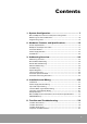
Contents 1. System Configuration ................................................. 7 NX-CPU700p PLC Features and System Configuration............................... 7 Module Types and Combinations ............................................................... 10 Programming Tools...................................................................................... 14 2. Hardware Features and Specifications ..................... 15 Overall Specifications....................................................
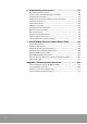
6. Programming Instructions ........................................ 87 Basic Sequence Instructions ........................................................................ 87 Timer, Counter and Shift Register Instructions.......................................... 88 Comparison Instructions .............................................................................. 89 Substitution, Increment and Decrement Instructions................................ 89 Arithmetic Instructions ............................
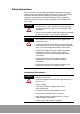
Safety Instructions Please read this manual and the related documentation thoroughly and familiarize yourself with product information, safety instructions and other directions before installing, operating, performing inspection and preventive maintenance. Make sure to follow the directions correctly to ensure normal operation of the product and your safety.
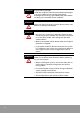
ATTENTION Electrostatic Discharges Under dry condition, excessive electrostatic discharges may occur. Make sure to remove electrostatic discharges by touching a grounded metal piece before touching your controller system modules. ATTENTION Cleaning Never use chemicals such as thinner because they melt, deform or discolor PCB boards. ATTENTION Precautions for use of power • Run your PLC system only after the I/O devices and motor devices have started.
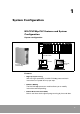
1 System Configuration NX-CPU700p PLC Features and System Configuration System configuration NX-Y16RV RY O UT NX-Y16RV RY O UT NX-Y16RV RY O UT NX-Y16RV RY O UT NX-Y32T TR OU T NX-X32D D C IN NX-X64D D C IN NX-X64D D C IN C PU NX-CPU700p POWER INIT TEST RUN RMT 40 39 1 2 40 39 1 2 1 2 1 2 PROG Programmable Controller COM RS232C OPEN TOOL RS232C 2 1 39 40 2 1 39 40 39 40 39 40 1 2 1 2 1 2 1 2 3 4 3 4 3 4 3 4 5 5 5 5 6 6 6 6 7 7 7 7 8 9 8 9 8 9 8
• High-capacity programming and memory backup The NX-CPU700p allows you to program up to 20K words. Built-in flash EEPROM allows you to save programs separately. • Self-diagnostics Self-diagnostics allows you to minimize system errors and maximize diagnostic efficiency. • Maximum 1600 I/O points With a 12-slot base backplane and a 12-slot expansion backplane, you can use up to 1600 I/O points (when all I/Os are configured with 64-point digital I/O modules).
I/O Backplanes and I/O Points 3-Slot Type 5-Slot Type NX-BASE03 48 Points: 16-point I/O 192 Points: 32-point I/O 8-Slot Type NX-BASE0) 80 Points: 16-point I/O 320 Points: 64-point I/O 10-Slot Type NX-BASE08 128 Points: 16-point I/O 512 Points: 64-point I/O NX-BASE10 160 Points: 16-point I/O 640 Points: 64-point I/O 12-Slot Type NX-BASE12 192 Points: 16-point I/O 768 Points: 64-point I/O • Flexible system configuration: 5 types of backplane (3-, 5-, 8-, 10and 12-slot) The NX-CPU700p PLC has 5 type
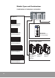
Module Types and Combinations Combinations of backplanes and modules Backplanea Processor module NX-CPU700p RUN PROG TEST BATT COM1 COM2 ERROR CP U 3-slot type: NX-BASE03 (common for base and expansion backplanes) INIT TEST RUN RMT PROG COM 1 RS232C RS485 5-slot type: NX-BASE05 (common for base and expansion backplanes) 8-slot type: NX-BASE08 (common for base and expansion backplanes) COM 1 RS232C RS485 NX-CPU700p 20k step base memory 2 ports (RS232/RS485) Power supply modules R 0 70 10-slot
*: Available with NX-CPU700p v2.
Processor Module Specialty Module (1) NX-CPU700p 20k step, 0.2 µs 2 comm. ports WinGPC S/W Specialty Specialty Module Module (2) (2) A/D, D/A, RTD, TC I/O Module High-performance, high-speed counter (4CH) 16-point type CCU, SCU High-speed counter (1, 2CH) Positioning module (1, 2, 3, 4 axes) 64-point type DevicedNet System Pulse output module (4CH) Software & cables 32-point type Remote I/O system Programming tool: WinGPC S/W MW-LINK system Comm.
Available Combinations and Restrictions Restrictions by Module ○ : Available, △ : Version 2.
Programming Tools Tools required for programming The following tools are required when programming with WinGPC.
2 Hardware Features and Specifications Overall Specifications General specifications Item Temperature Humidity Specifications Operating 0 °C to +55 °C (32 °F to 131 °F) Storage -25 °C to +70 °C (-13 °F to 158 °F) Operating 30 to 85% RH (non-condensing) Storage 30 to 85% RH (non-condensing) Withstand voltage 1500V ac for 1 minute between external terminal (ac) and frame ground (FG) 500V ac for 1 minute between external terminal (dc) and frame ground (FG) Insulation resistance 100 MΩ or more at 5
Performance specifications Processor NX-CPU700p Control method External I/O Instructions 1,600 points Basic 28 types Advanced 150 types Basic instructions Processing speed Advanced instructions Max. program size 0.2 to 0.4 µs per step 0.4 to several tens of µs per step 20K words I/O contact (R) R0.0 to R127.15 (2,048 points, 128 words) Link contact (L) L0.0 to L63.
Backplane and Expansion Cable Backplane (NX-BASE03, NX-BASE05, NX-BASE08, NX-BASE10, NX-BASE12) Description 1. Backplane mounting hole This hole is for mounting a backplane on a control panel (control box). Use M5 screw for mounting. 2. Module mounting guide holes When mounting a module on the backplane, align the mounting clamp of the module with this hole.
Backplane types Type Number of slots Catalog number Weight (g) 3 NX-BASE03 250g 5 NX-BASE05 330g 8 NX-BASE08 460g 10 NX-BASE10 570g 12 NX-BASE12 660g Common for base and expansion backplanes Expansion cable (NX-EXPCBL) Expansion cable 18 Cable length Catalog number Remarks 1.5m NX-EXPCBL15 0.
Processor Module NX-CPU700p processor module 1 NX-CPU700p INIT TEST RUN RMT PROG COM1 RS232C RS485 CPU COM 1 COM 2 E RRO R RUN P ROG TE S T B AT T 2 3 4 4 3 2 1 8 7 6 5 4 3 2 1 4 COM1 RS232C RS485 6 5 ON (Front) (Bottom) (Side) • Hardware features 1. Status LED Indicates the operation status of PLC, such as run, stop, error, and alarm. 2. Initialize/Test switch Test switch is unused at present. 3. Mode switch Used to change the operation mode of the controller. 4.
• Status LEDs LED Color Description RUN Green On when the processor is running. PROG Green On when the program can be edited. BATT Red TEST Green Not used COM1 Green Flashing when the processor is communicating via COM1. COM2 Green Flashing when the processor is communicating via COM2. ERROR Red On when the battery is not mounted or is low. On when a processor error occurs. • Mode switch Mode Description RUN Sets the processor operation mode to RUN mode.
• Operating condition setting switches • Switch for termination resistance setting (DIP switch 1) Pin No. 4 Pin setting Description ON ON For RS-485 communication, set both pins 3 and 4 to On if the system is a termination station. (Enables termination for COM1 terminal) OFF OFF For RS-485 communication, set both pins 3 and 4 to Off if the system is not a termination station.
Power Supply Module 1 POWER POWER 2 FUSE USE ONLY 250V 1.5A FUSE USE ONLY 250V 1.5A + N 4 85-264 VAC 24V DC L - FRAME GROUND 5 FRAME GROUND + 6 24VDC 0.5A OUTPUT - 3 NX-POWER NX-PWRDC • Hardware features 1. Power status LED Turns on when power is on. 2. Power fuse holder 3. Terminal block Terminal block for power wiring. Crimped terminal for M3.5 can be used. Detachable. 4. Power input terminal 110-240V AC Free Voltage power input terminal (NX-PWR220 is only for 220V ac). 5.
• Specifications Input type Catalog number Input rated voltage Allowed voltage range Input power frequency Inrush current Rated output current Fuse Weight ATTENTION ATTENTION AC input power NX-POWER NX-PWR220 110 to 220V AC 220V AC Free Voltage 85 to 264V AC 176 to 264V AC 47 to 63Hz 20A or less 5V 4.0A, 24V 0.5A 5V 6.0A 250V 1.5A 350g 300g DC input power NX-PWRDC 24V DC 24V DC ± 10% 5V 3.0A 320g NX-POWER module does not guarantee protection against momentary power failure at 110V ac.
I/O Modules 1 8 F NX-Y32T 0 8 10 18 7 F 17 1F NX-Y64T 0 8 10 18 7 F 17 1F TR OUT 7 1 TR OUT 0 DC IN NX-X16D 1 2 1 3 ¥– ¥ 2 5 40 39 1 2 4 4 39 16-point type (A Type) 40 32-point type (B Type) 2 1 39 40 64-point type (C Type) • Hardware features 1. I/O Status LED Shows I/O ON/OFF status. 2. Terminal block fixing screw Fixes detachable terminal block on the unit. 3. Terminal block (20P, detachable terminal block) Terminal block for I/O and power wiring. Crimped terminal for M3.
Input unit specifications Product name DC input module Catalog number NX-X16D Number of input points 16 points Insulation method Photocoupler Rated input voltage 12 to 24V Operating voltage range 10.2 to 26.4V Max. input current 10mA or less (for 24V) ON voltage/current Min. 9.6V OFF voltage/current Max. 2.5V Input impedance: Approx.
Product name DC input module Catalog number NX-X32D Number of input points 32 points Insulation method Photocoupler Rated input voltage 12 to 24V Use voltage range 10.2 to 26.4V Max. input current 10mA or less (for 24V) ON voltage/current Min. 9.6V OFF voltage/current Max. 2.5V Approx.
Product name DC input module Catalog number NX-X64D Number of input points 64 points Insulation method Photocoupler Rated input voltage 12 to 24V Operating voltage range 10.2 to 26.4V Max. input current 10mA or less (for 24V) ON voltage/current Min. 9.6V OFF voltage/current Max. 2.5V Input impedance Approx.
Product name AC input module Catalog number NX-X16A110 Number of input points 16 points Insulation method Photocoupler Rated input voltage AC 100 to 120V AC 200 to 240V Operating voltage range AC 85 to 132V AC 170 to 264V Max. input current 20mA or less ON voltage/current Min. 80V/6mA Min. 160V/6mA OFF voltage/current Max. 30V/3mA Max. 50V/3mA Input impedance Approx. 15KΩ Approx.
Output module specifications Product name RELAY output module Catalog number NX-Y16R Number of output points 16 points Insulation method Photocoupler Rated load voltage 2A 250V AC, 2A 30V DC Response time Life time OFF → ON NX-Y16RV 10ms or less ON → OFF 10ms or less Mechanical 30 million times Electric 200 thousand times External power supply 24V 150mA or less Surge protection N/A Internal current consumption (5V) 120mA or less Common method 8 points/1COM Operation indicator L
Product name RELAY output module Catalog number NX-Y32RV Number of output points 32 points Insulation method Photocoupler Rated load voltage 1A 250V AC, 1A 30V DC OFF → ON Response time Life time 10ms or less ON → OFF 10ms or less Mechanical 30 million times Electric 200 thousand times External power supply 24V 150mA or less Surge protection circuit Varistor Internal current consumption (5V) 180mA or less Common method 32 points/1COM Operation indicator LED External cable connec
Product name TR output module Catalog number NX-Y16T Number of input points 16 points Insulation method Photocoupler Rated load voltage 12 to 24V DC Operating load voltage range 10 to 30V DC Max. load current 0.
Product name TR output module Catalog number NX-Y32T Number of input points Insulation method Photocoupler Rated load voltage 12 to 24V DC Operating load voltage range 10 to 30V AC Max. load current 0.
Product name TR output module Catalog number NX-Y64T Number of input points 64 points Insulation method Photocoupler Rated load voltage 12 to 24V DC Operating load voltage range 10 to 30V AC Max. load current 0.
Product name SSR output module Catalog number NX-Y16SSR Number of input points 16 points Insulation method SSR Rated load voltage 100 to 240V AC Operating load voltage range 85 to 264V AC Max. load current 0.5A/point OFF state leakage current 100 µA or less Response time OFF → ON 1ms or less ON → OFF 0.
3 Addressing Overview Addressing Overview All the memory used for external I/O processing and internal data processing has always both address and data (the content). Addressing space is classified as R, L, M, K, F, TC, and W. These letters are used to designate a specific area in memory as shown in the following table. Memory areas Addresses Description R000.0 to R127.15 • Local I/O memory area that can be set when configuring I/O module. • 2048 points, 128 words R640.0 to R127.
N The R, L, M, K, F, and TC areas can be used for both bit and word addressing. N The W area can be used to process word data only. N The L area can be used as internal contacts. N Keep contact (K), data register (W), and counter's preset value register retain their last values before power was removed. Cleared when a new program is downloaded. Bit and Word Addressing A bit address is composed of a character (R, L, M, K, F) that identifies its type, a five digit word address (0.0 to 127.
Double Word Addressing Double word addressing is same with word addressing, except that 32-bit data is referenced by the specified address and its next address. The type of instruction used determines which addressing, word or double word addressing, is applied. For comparison instructions, the programmer must be in “Double Mode” to enter a double-word comparison.
Absolute Addressing In LDR, DLDR, STO, and DSTO instructions, an absolute address is used to indirectly reference a register or to utilize the built-in communication port. Classification Register address Absolute address Absolute address Register address Classification Dec. Hex.
I/O Addressing Addressing is based on the location of the module. Example 1: 8-slot system Slot No.
Occupied I/O points by module (unit: word) The table below shows the occupied I/O points for each module when the memory space is allocated automatically by the system.
Special Registers Word registers F000 to F015 Address Function Description F000 register System check/control F001 register System check/clock F002 register Link control Link installation and operation mode setting F003 register Link control Link installation and operation mode setting F004 register Link status flag Link participating station information F005 register Link status flag Link participating station information F006 register Link status flag Link data receiving information f
Word register F000 (F0.0 to F0.15) Only a bit process is available. 42 Address Function Description Normal status F0.00 System check When the power is applied, the system self-checks the ROM. Should any fault exist, the error lamp is turned on. Output and operation are halted. OFF F0.01 CPU ROM check When the power is applied, the system self-checks the ROM. Should any fault exist, the error lamp is turned on. Output and operation are halted. OFF F0.
Word register F1 (F1.0 to F1.15) Only a bit process is available. Address Function Description Remarks F1.0 First single scan Maintain On state for first single-scan period, when the CPU shanges its status stop to Run. F1.1 Scan clock F1.2 0.02-second clock Cycle On/Off state for each scan during the program. (1Scan On, 1Scan Off) 10 ms: On, 10 ms: Off 10m S 10m S 10m S 50m S 50m S 50m S 5 00m S 5 00m S 5 00m S 50 ms: On, 50 ms: Off F1.3 0.1-second clock 500 ms: On, 500 ms: Off F1.
Word register F12 (F12.0 to F12.15) Only a bit process is available. Address Function F12.0 RTC check F12.2 Description Remarks On when the RTC is enabled. - Flash On when the 9.6 KW of flash memory is installed. - F12.3 Flash On when the 16 KW of flash memory is installed. - F12.5 Battery error On when the battery is not connected or the voltage is lower than the backup voltage. - F12.7 Periodical scan error F12.10 RTC set error F12.
Special registers SR017 to SR511 (W2577 to W3071) May be changed - each is composed of 1 word. Address Function Description Gives result of self-diagnosis by CPU. Indicates error content . MSB SR017 System error information ← 7 6 5 4 3 2 1 0 Watchdog time error = ON Undefined instruction = ON Peripheral device fault = ON Misc.
Program syntax error status register SR30 (W2590) Indicates the result of the automatic check on the user program syntax when the programmer or GPC executes a syntax check, and when the operation mode is switched from the Stop state to the Run state. If the value of W2590 is not zero, F004 bit turns On. The error lamp also turns On. Error correction method: Find the error in the CPU online mode and then correct the program.
Real-time clock registers SR289 to SR297 (W2849 to W2857) Sets the time of the built-in clock (RTC) and stores and displays the present time. Data is stored in BCD format.
Timer/Counter Area Timer/counter set value and present value addresses Channel 0 1 2 3 4 5 6 7 8 9 10 11 12 13 14 15 16 17 18 19 20 21 22 23 24 25 26 27 28 29 30 31 32 33 34 35 36 37 38 39 Set value (SV) W2048 W2049 W2050 W2051 W2052 W2053 W2054 W2055 W2056 W2057 W2058 W2059 W2060 W2061 W2062 W2063 W2064 W2065 W2066 W2067 W2068 W2069 W2070 W2071 W2072 W2073 W2074 W2075 W2076 W2077 W2078 W2079 W2080 W2081 W2082 W2083 W2084 W2085 W2086 W2087 Present value (PV) W2304 W2305 W2306 W2307 W2308 W2309 W2310 W2311
Channel 120 121 122 123 124 125 126 127 128 129 130 131 132 133 134 135 136 137 138 139 140 141 142 143 144 145 146 147 148 149 150 151 152 153 154 155 156 157 158 159 160 161 162 163 164 165 NOTE Set value (SV) W2168 W2169 W2170 W2171 W2172 W2173 W2174 W2175 W2176 W2177 W2178 W2179 W2180 W2181 W2182 W2183 W2184 W2185 W2186 W2187 W2188 W2189 W2190 W2191 W2192 W2193 W2194 W2195 W2196 W2197 W2198 W2199 W2200 W2201 W2202 W2203 W2204 W2205 W2206 W2207 W2208 W2209 W2210 W2211 W2212 W2213 Present value (PV) W24
Address (register) Address refers to the location of memory being used. It can refer to the external I/O module and internal memory. An address is categorized into 1 bit, 16 bits (word), or 32 bits (double word). Bit A bit is the minimum module required for calculation. It can be either On (1) or Off (0). Byte A byte is made up of 8 bits. It can hold data values from 0 to 255. In base 16, or hexadecimal, a byte can be expressed as 0 to FF. You cannot have a value greater than 255 when using one byte.
BCD (Binary Coded Decimal) BCD is used to express a decimal digit (0 to 9) using 4 bits. Conversion of BCD values can be done in hexadecimal calculations. Example: 59 (BCD) = 59 (HEX), 32 (BCD) = 32 (HEX) Flash ROM It refers to a ROM (EEPROM) that stores programs. Since its contents can be deleted periodically, it is frequently used for equipments that deals with programs such as a PLC.
• For bit operations, such as setting, resetting, shifting, or rotating Use the M, K, and R area. You cannot perform bit operations in the W area. • When you want to refer to or modify the set value of the timer or counter. Refer to or modify W2048 to W2303 or SV0 to SV255. • When you want to refer to or modify the present value of the timer or counter. Refer to or modify the address area from W2304 to W2559 or from PV0 to PV255. The value holds true in STOP (PROG.) state in this area.
Allowed Functions in Operation Modes 5=On, ◑ =Flashing, ● =Off Operation mode selector switch Operation mode RUN LED PROG LED Program change Data change Initialize switch is enabled Mode at power off-on RUN 5 ● Disallowed Allowed ○ Run STOP ● Allowed Allowed ○ Run RUN 5 Allowed Allowed ○ Run PAUSE ◑ Allowed Allowed ○ Pause STOP ● 5 5 5 5 Allowed Allowed ○ Stop RUN REMOTE PROG LED status When the PROG.LED is on, you can change the user program.
• Watchdog time initialization The watchdog elapsed time value is set to 0. (This value is the watchdog calculation point until the next scan.) The following illustration shows the difference between the relay board and PLC sequence processing. The relay carries out all sequences simultaneously while the PLC processes sequentially throughout the program.
4 Installation and Wiring Installation Installation space and environment External dimensions (mm) unit (mm) 3-slot type 5-slot type 8-slot type 10-slot type 12-slot type A (mm) 205.0 276.0 381.0 452.0 522.0 B (mm) 183.8 254.2 359.8 430.2 500.
Installation location Be sure to maintain a sufficient distance from wiring ducts, and other machines below and above the module for proper ventilation. Do not install the modules stacked up or horizontally. Doing so will prevent proper cooling of the module and cause overheating inside the PLC (programmable controller). Do not install the module above devices which generate heat such as heaters, transistors or large scale resistors.
Avoid installing the module in the following conditions • Ambient temperature outside the range of 0 to 55 °C • Ambient humidity outside the range of 30 to 85% RH • Sudden temperature changes causing condensation • Inflammable or corrosive gases • Excessive airborne dust, metal particles, salinity • Benzene, thinner, alcohol, other organic solvents or strong alkaline solutions such as ammonia or caustic soda • Excessive vibration or shock • Direct sunlight • Location near high-tension wires
N It is recommended that you use crimped terminal for wiring. N Open type terminal N 7.0mm or less Circular terminal 7.0mm or less Φ 3.7 to Φ 4.3 hole Use 2mm2 twisted pair cable or larger • Use power supply wire that is thicker than 2mm2 to minimize voltage drops. • Use twisted pair cable to minimize noise effects.
Grounding Ground the PLC for noisy environments • Connected to the metal part of backplane, the frame ground terminal is connected to a solid earth ground. • Use ground wires with a minimum of 2mm2 and the triple grounding connection which has a resistance of less than 100 Ω. • The point of grounding should be as close to the PLC as possible and the ground wire should be as short as possible. • If two devices share a single ground point, it may produce an adverse effect.
Input and Output Wiring Input wiring Checkpoints for input module wiring There can be limits on the number of points that can be simultaneously turned on, based on the module type. Check such limits in the specifications of each input module. In particular, be careful when using in high ambient temperature. The connection method for each type of input device including sensor is described below.
Connection example with AC input device Contact output type AC input unit Input terminal COM terminal Non-contact output type AC input unit Input terminal COM terminal Cautions when using lead switch with LED Even when using input contact with embedded serial LED such as lead switch with LED, make sure to supply voltage higher than ON voltage to the PLC input terminal. Pay extra attention, in particular, when connecting multiple switches in serial.
Cautions when using 2 wired type Use a breeder resistor as below when the leakage current from 2 wired type photoelectric switch or proximity switch keeps flowing into the PLC. DC 12-24V type input unit (OFF voltage 2.5V, input impedance 3 KΩ) 2 wired sensor DC input unit Internal Circuit Input terminal Breeder resistor COM terminal I: Leakage current (mA) R: Breeder resistance (KΩ) Since the OFF voltage of input is 2.
Cautions when using limit switch with LED Use a breeder resistor as below when the leakage current from limit switch with LED keeps flowing into the PLC or LED is accidentally turned on. DC 12-24V type input unit (OFF voltage 2.5V, input impedance 3 KΩ) Limit switch with LED DC input unit Internal Circuit Input terminal Breeder resistor COM terminal r: Internal resistance of limit switch (KΩ) R: Breeder resistance (KΩ) Since the OFF voltage of the input is 2.
Output wiring Checkpoints for output unit wiring N There can be limits on the number of points that can be simultaneously turned on or load current, based on the unit type. Refer to the specification of each unit. Pay extra attention, in particular, when ambient temperature is high. N Connect protection circuit to inductive load or capacity load, etc. as below. N There can be current limitation per Common for output units, so make sure not to exceed the allowed range.
Cautions when using capacity load Use protection circuit as below to minimize the effect of a load with high inrush current. Output unit Resistor Output terminal Load COM terminal Output unit Output terminal Inductance Load COM terminal Use an external fuse to protect against overload N Units embedded with fuse can prevent damages in case of output shortage.
Terminal Block Type Module Wiring Compressed terminal, M3.0 The terminal base for the NX70 PLC I/O modules (Terminal Type) uses M3.0 terminal screw. Use the following compressed terminals for terminal wiring. Open terminal Circular terminal 7.0mm or less 7.0mm or less Removable terminal block N Terminal block of this type of I/O unit can be separated from the unit with wires connected, by unfastening the screws on both ends. N Make sure to refasten the screws after wiring.
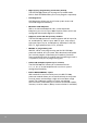
Connector Type Module Wiring Wiring Wiring method Both NX700 32-point I/O module (NX-X32D, NX-Y32RV, NX-Y32T) and 64-point I/O module (NX-X64D, NX-Y64T) use 40-pin MIL type connectors. To connect to external devices, 1. Insert each pin into socket 2. or, use harness with flat cables. (Available on the market) Connecting PIN type PIN type connection. Insert each PIN into a socket. Detail wirings are shown on the next page.
Connecting with harness (Using flat cable connector) 40-pin flat cable connector is used, and 20 crimped terminals are connected at the end. Its total length is 1.5m. Direct connection to the unit. Product name Flat cable ASS'Y Catalog number Product specifications NX-CBLDC DC IN 32 points, 64 points Connectors harness cable 1.5m NX-CBLTR TR OUT 32 points, 64 points Connectors harness cable 1.5m NX-CBLRY Relay OUT 32 points Connectors harness cable 1.
Pressure welding socket for PIN type connection Direct pressure welding with clothings on saves wiring time and efforts. Wiring 1. Bend the contact part at a carrier, and set it into the pressure welding device. (Matsushita Electric Industrial Co.: AXY52000) 2. Insert both cables with case on until touching each other, and hold the pressure welder slightly. 3. Insert the cables into the housing once welding is done. Contact removal pin for wiring failure.
Wiring flat cable connector Cautions when using flat cable connector When a flat cable connector is used for direct connection, the mapping between cable No. and I/O No. is as follows: Connecting 32-point unit (NX-X32D, NX-Y32T, NX-Y32RV) 1 DC IN NX-X32D 2 Product name Flat cable (1.
Connecting 64-point unit (NX-X64D, NX-Y64T) Product name Flat cable (1.5m) D C IN NX-X64D Flat cable Catalog number Specifications NX-CBLDC DC IN 64 points (NX-X64D) NX-CBLTR TR OUT 64 points (NX-Y64T) Flat cable Mapping table between flat cable No.
Safety Measures Precautions regarding system design In certain applications, malfunction may occur for the following reasons: • The timing difference between opening and closing of the PLC power supply, the I/O modules and power equipment • An operation time lag when a momentary power failure occurs • Abnormality in the PLC, external power supply, or other devices In order to prevent a malfunction resulting in system shutdown choose the adequate safety measures listed in the following: Interlock circui
NX-CPU700p Processor Module Communications Specifications Connection specification RS485 RS232C Transfer distance (Max) 1.
EEPROM Backup What's EEPROM backup? EEPROM (Electric Erase Programmable Read Only Memory) can retain the data when the power is turned off, and erase or record data when the power is turned on. This function allows you to retain the PLC program when the power is turned off. And it also erases an existing program and records a new one when correcting or storing a program after turning on the power. Applicable models The types of EEPROM can be defined by its characteristics.
5 Test Run and Troubleshooting Test Run Precautions Before installing the I/O wiring of the PLC and supplying power, check the following items. Item The connection of the power cable and the I/O cables Grounding Battery Emergency stop circuit Power source What to check • • • • • • Check if the wiring is secured. Check if the terminal screws are tightened. Check if the parts of connectors are properly joined. Check if the I/O modules are firmly fixed. Check if the power cable is securely connected.
Test Run Procedure When the PLC has been installed and wired, begin test run in the following order. Item What to check/do Supply power • Check if the input voltage of the power supply module is within specifications. • Check if the power voltage for the I/O modules is within specifications. • Connect WinGPC to the CPU module. (Set the CPU module to the PROG mode.) • Turn on the power source. • Check the LED display of the power supply module. Initialize memory • Initialize the PLC using WinGPC.
Test Run Flow Charts System check flow chart When you encounter problems during startup or test run, first of all, figure out the problems thoroughly. Check if the problems can be reproduced, and analyze the relevance to other devices. Then refer to the system check flow chart.
Power check flow chart 78
Run check flow chart 79
Error check flow chart 80
I/O check flow chart This page presents an example of a troubleshooting procedure based on the right circuit.
External environment check flow chart 82
Inspection and Maintenance Inspection and maintenance Symptom Possible cause Action Power supply LED will not illuminate. Fuse blows Replace the fuse Fuse blows frequently. Short circuit or defective part Replace the power supply or the CPU module Program errors Correct the program Run LED will not illuminate. Power line defect Replace the CPU module Output will not turn to On state during Run.
Output module Symptom No outputs on an output module will turn On. No outputs on an output module will turn Off. One or more inputs on an I/O module will not change to On state (LED is illuminated). One or more inputs on an I/O module will not change to On state (LED is not illuminated). One or more outputs on an I/O module will not change to On state (LED is illuminated). One or more outputs on an I/O module will not turn Off (LED is not illuminated). Output changes On/Off state erratically.
Periodic inspection and maintenance items The NX-CPU700p controller requires periodic inspection and maintenance for proper operation. The following items should be checked every six months, but the period can be shortened according to the operational environment.
6 Programming Instructions IMPORTANT Refer to the NX7/NX70/NX700 Instruction Set Reference Manual for detailed information on the NX7, NX70, and NX700 instruction set and for application examples to show the instruction set in use. Basic Sequence Instructions Mnemonic Name Ladder Symbol Description STR Start STN Start Not AND And ANN And Not OR Or ORN Or Not OUT Out (OUT) SET Set RST Reset (SET) (RST) NOT Not STR DIF Start Differential STR DFN Start Dif.
Timer, Counter and Shift Register Instructions Mnemonic Name Ladder Symbol TIM TIM On Delay Timer Ch=00010 SV=00050 Description Remarks Turns on after set delay Input input on time from Time base: Ch 0 to 63 = 0.01s Ch 64 to 255 = 0.
Comparison Instructions Mnemonic Name STR == START == AND == AND == OR == OR == STR <> START <> AND <> AND <> OR <> OR <> STR > START > AND > AND > OR > OR > STR >= START >= AND >= AND >= OR >= OR >= STR <= START <= AND <= AND <= OR <= OR <= STR < START < AND < AND < OR < OR < Word ladder symbol == A= B= <> A= B= > A= B= >= A= B= <= A= B= < A= B= Double word ladder symbol D== A= B= D<> A= B= Description On if A is equal to B.
Arithmetic Instructions Mnemonic ADD (DADD) ADDB (DADDB) SUB (DSUB) SUBB (DSUBB) MUL (DMUL) MULB (DMULB) DIV (DDIV) DIVB (DDIVB) ADC (DADC) ADCB (DADCB) SBC (DSBC) SBCB (DSBCB) ABS (DABS) 90 Name Decimal addition BCD addition Decimal subtraction BCD subtraction Decimal multiplication BCD multiplication Decimal division BCD division Word ladder symbol Double word ladder symbol Description D = S1 + S2 (Decimal operation) D = S1 + S2 (BCD operation) D = S1 - S2 (Decimal operation) D = S1 - S2 (BCD op
Logical Instructions Mnemonic Name WAND (DAND) AND (logical multiply) Word ladder symbol Double word ladder symbol Description Store AND of S1 and S2 in D Store OR of S1 and S2 in D WOR (DOR) OR (logical sum) WXOR (DXOR) Exclusive OR (exclusive logical sum) WXNR (DXNR) Store exclusive OR of S1 and S2 in D Store exclusive OR NOT of S1 and S2 in D 1 (ON if they are equal) Exclusive OR NOT (equivalence) Rotation Instructions Mnemonic Instruction RLC (DRLC) Rotate left without carry RRC (DRRC
Word Conversion Instructions Mnemonic BCD (DBCD) Name Word ladder symbol Double word ladder symbol Description Convert binary value of S to BCD and store it in D. BCD Conversion S ...... 0 0 1 1 1 1 1 1 =63(DEC) D ...... 0 1 1 0 0 0 1 1 =$63 (BCD) BIN (DBIN) Convert BCD of S to binary number and store it in D. Binary Conversion Store the location of the highest set bit in S in D.
Bit Conversion Instructions Mnemonic Name Word ladder symbol Double word ladder symbol Description Set Nth bit of D to 1. BSET Bit Set When N=15 1 (N=0~15) Reset Nth bit of D to 0. BRST Bit Reset When N=3 Invert Nth bit of D. BNOT Bit Not When N=4 Store the value of Nth bit of D to F1.8. BTST Bit Test When N=6 Store the number of bits in S that are 1 to D. SUM Sum No of 1=7 D=7 Set carry bit (F1.8) to 1. SC Set Carry Reset carry bit (F1.8) to 0. RC Reset Carry Invert carry bit (F1.8).
Move Instructions Mnemonic Name Word ladder symbol Double word ladder symbol Description Copy Ns words from Sr to D. MOV Move When N=3 Repeatedly copy the value V to the Ns words starting from D. FMOV Fill Move When N=4 Move Ns bits from the bit address Sb to the bit address Db. BMOV Bit Move When N=4 BFMV Bit Fill Move Repeatedly copy the bit value V to the N bits staring from the bit address Db.
Program Control Instructions Mnemonic Name FOR (DFOR) For Loop NEXT Next JMP Jump Word ladder symbol Double word ladder symbol Description Execute instructions in the block between FOR and corresponding NEXT. Repeat execution D times. Decrement D of FOR instruction by 1. If it is not zero, repeat execution from FOR instruction. Jump to the position marked LBL L (label number). (L: 0 to 63) LBL Label Position jumped to by the corresponding JMP instruction.
System Control Instructions Mnemonic Name INPR Input Refresh Word ladder symbol Double word ladder symbol Description Refresh external input (Receive input signal during program execution). Ch is external input word address. OUTR Output Refresh Refresh external output (Send output signal during program execution). Ch is external output word address. 96 WAT Watchdog Timer END END Clear watchdog scan time. End of program. This instruction is automatically added by WinGPC.
Communications Control Instructions Mnemonic Name Read Data READ (from shared memory of high performance module) Write Data WRITE (to shared memory of high performance module) Read Remote Slave Data RMRD (from shared memory of high performance module) Write Remote Slave Data RMWR (to shared memory of high performance module) Word ladder symbol READ TO=RR1 SZ=NR3 FR=NN5:NR6 WRITE TO=NN1:NR2 SZ=NR3 FR=NN5 RMRD TO=NR1:RR2 NT=NN3:NN4 FR=NN5:NR6 RMWR NT=NN1:NN2 TO=NN3:NR4 FR=NR5:NR6 RECV RECV
7 NX-CPU700p System Product Dimensions System Dimensions unit (mm) unit (mm) 3-slot type 5-slot type 8-slot type 10-slot type 12-slot type A (mm) 205.0 276.0 381.0 452.0 522.0 B (mm) 183.8 254.2 359.8 430.2 500.6 Backplane Dimensions unit (mm) ¥ı 5.0 * 4 27.5 L 7.0 22.5 Slots A L 3 205.0 153.8 5 276.0 224.2 8 381.0 329.8 10 452.0 400.2 12 522.0 470.
Power Supply Module Dimensions) unit (mm) POWER N X 700 R WE PO Programmable Controller 115.5 le ab mm er ra ll og ro Pr ont C OPEN EN OP UN SAMSUNG S 104.0 43.0 Processor and I/O Modules Dimensions unit (mm) NX-X16D NX-X64D D C IN ERROR B AT T A LA R M D C IN RUN PROG TE S T B R EA K C PU N X-CPU 700p INIT TEST RUN 1 RMT PROG 3 2 4 5 6 115.5 7 CCOM OM1 RS232C RS232C RS485 8 9 10 11 12 13 14 15 COM1 TOOL RS232C RS232C RS485 16 17 18 19 20 35.0 100 104.
Specialty Module Dimensions unit (mm) 00 N X-ETHER N ET RESET LINK NO AU I 0 115.5 EtherN et NX-SC U SCU M W LIN K NX-M W LINK COM1 RS232C RS485 T ++ -FG F.G 35.0 COM2 RS232C RS485 12V 35.0 35.0 104.0 NX-IOLINK Module Dimensions unit (mm) 4 3 2 1 MODE SW OFF ON 105.0 + 24V D C IN P U T + LIN E FG 70.
Decimal, Bin, Hex, BCD, Gray Code Cross-reference Table 102
ASCII Code Table b8 b8 b7 b6 b5 b7 0 0 0 0 1 1 1 1 b6 0 0 1 1 0 0 1 1 b5 0 1 0 1 0 1 0 1 0 1 2 3 4 5 6 7 C b4 b3 b2 b1 0 0 0 0 0 NUL DEL SPACE 0 @ P ` p 0 0 0 1 1 SOH DC 1 ! 1 A Q a q 0 0 1 0 2 STX DC 2 “ 2 B R b r 0 0 1 1 3 ETX DC 3 # 3 C S c s 0 1 0 0 4 EOT DC 4 $ 4 D T d t 0 1 0 1 5 ENQ NAK % 5 E U e u 0 1 1 0 6 ACK SYN & 6 F V f v 0 1 1 1 7 BEL ETB ' 7 G W g
Appendix Communication Protocols The communication protocol of NX-CPU700p PLC provides a complete method of communications between the graphic consol programmers (WinGPC) and the PLC by controlling programs, CPU status, and I/O at user’s convenience. The user can easily expand the capabilities of the overall PLC system by communicating to the PLC using a variety of peripheral communications equipment in accordance with the following communication protocols and procedures.
Communication Protocols Step 1-Q Query Query Q (Query) is a signal sent from the peripheral devices to the PLC after setting the network ID number and the function code for the PLC to communicate with. Step 2-QA Query QueryAcknowledge QA (Query Acknowledge) is a signal sent from the PLC to the peripheral devices, indicating that the Q signal from the peripheral device was received.
When several CPU modules are connected to one communication network, they must use individual ID numbers. The PLC’s network ID number is configured using the WinGPC. Communication steps The NX CPU can support 2-step or 4-step communication methods. The communication methods are easily distinguished each other by selecting and sending the function code of the Q frame. Even for the 4step method, the 2-step method can be used for the repeated function.
2-step communication method No communication error Peripheral device PLC When R is not received 3 seconds Peripheral device PLC Response to repeated function code Peripheral device PLC 4-step communication method No communication error For the internal processing of the PLC CPU send RR at least 5 msec after receiving QA.
Function codes included in the query Each function code is 1 byte. When the PLC receives a query (Q), the function code of the final response (R) is formed by adding $80 (hex) to the function code sent by the query. The value added to the function code sent by the query differs for 2-step and 4-step by $20 (hex). The function code of the R message can be used by the peripheral device to verify that the correct Q message has been received by the PLC.
Cyclic Redundancy Checking (CRC) The CRC is a 2-byte checksum code attached to the end of the message by the sender to check if the communication frame is transmitted without error. The sender calculates the CRC when it sends one-byte message, and the receiver should also calculate the CRC from the data of the message.
Structure of Communication Frames The function code is explained with the example of Query and Response frame based on the 2-step communication. Query (Q) and Response (R) frame DA SA Function code Length Information CRC L Length of information area (byte) CRC H CRC-16 code (2 bytes) 1 to 255: 1 to 255 bytes 0: 256 bytes The frame is sent from SA to DA.
Read bits Read the content of the bits (R, L, M, K, F, or TC) assigned to the absolute address. Can read n consecutive bits (On/Off). Query (Q) frame DA SA $21 $03 BAS L H N CRC L H Number of bits to be read Length of information (byte) Absolute bit address (address of first bit to read) Refer to 3.3 Absolute Addressing Ex) K127.
Write bits Modify the contents of the bits stored in the absolute address (R, L, M, K, F, or TC). Change the bit state between On/Off. Can change multiple consecutive bytes. Query (Q) frame DA SA $22 N Base L H Base+0 bit value Base+N+1 bit value Base+N-3bit value - L CRC H To turn On the desired bit value from the base, enter $FF. To change to Off, enter $00. Absolute bit address (starting address) Refer to Absolute Addressing on Chapter 3.
Write words Change the content of the words (R, L, M, K, F, or W) assigned to the absolute address. Can read n consecutive words. Query (Q) frame DA SA $24 Base L H L Base+0word L H - Base+1word L H L CRC H n word values from the base words requested by the Q. Length L = Nx2+2 Response (R) frame DA SA $A2 $01 &00 L CRC H Fixed Read bits and words Read the bits and/or word contents of the assigned absolute addresses.
Write bits and words Read the bits and/or word contents of the assigned absolute addresses. Can read bits and words regardless of their order and location in memory. Query (Q) frame DA SA $26 AO L L H DO Method of assigning bit/word absolute address 15 14 13 0 Absolute Address(Bit/Word) 0 0 Absoulte bit address 0 1 Absoulte word address 1 X Not used Ax=A0, A1, .., An Dx=D0, D1, .., Dn A1 L H - L CRC H Assigning absolute addresses for bits Absolute address for the K127.
Communication Program Examples Users can write a communication program by using the following example. For more information, contact the sales or technical department. Program #include #include #include
Program Notes * Initialization of GPC card */ if(port_number == 1) PORTADD=0x3F0; if(port_number == 2) PORTADD=0x2F0; if ((port_number >= 3) && (port_number <=5)) { PORTADD=0x300; outportb(0x303,0xC0);/* Mode=2 of 8255 */ outportb(0x303,0x05);/* PC2=1 of 8255 :Disable IRQ2 */ outportb(0x301,0xFF);/* PB0=1 of 8255 :Sending Enable RS485*/ outportb(0x303,0x01);/* PC0=1 of 8255 :Serial Input Enable*/ if(port_number == 3) outportb(0x303,0x02);/* PC1=0 of 8255 :Select RS-232 */ if(port_number == 4) outportb(0x3
Notes Program void Job(void) { /* JobID=0 : Change to sending-mode for serial port */ /* JobID=1 : Transmit sending-frame */ /* JobID=2 : Change to receiving-mode for serial port */ /* JobID=3 : Address polling of ACK from CPU */ /* JobID=4 : Receive ACK from CPU */ /* JobID=5 : Change to sending-mode for serial port */ /* JobID=6 : Transmit RR-Frame */ /* JobID=7 : Change to receiving-mode for serial port */ /* JobID=8 : Address polling of RES from CPU */ /* JobID=9 : Receive RES from CPU */ /* JobID=10 :
Notes Program break; case 4: case 9:if(receiving_occuring()) { if(index
Program if(communication() == 0) printf("WRITE K0000-K0063 OK\n"); else printf("communication error\n"); receiving_frame[2]=4; /* EXAMPLE write WORD(K064-K0127) */ receiving_frame[3]=130; /* Number Of Byte For Information */ receiving_frame[4]=0x80; /* BASE(K000=$0180) LOW */ receiving_frame[5]=1; /* BASE HIGH */ for(i=0;i<=63;i++) { receiving_frame[i*2 +6]= lower_byte(K[i+64]); receiving_frame[i*2 +7]= upper_byte(K[i+64]); } if(communication() == 0) printf("WRITE K0064-K0127 OK\n"); else printf("communicat
NX700 Series Controller NX-CPU700p User Manual www.samsungautomation.co.kr Rockwell Samsung Automation Technical Support 447-6, Gongse-Ri, Giheung-Eup, Youngin-City, Gyeonggi-Do, South Korea, 449-902 Tel: 82-31-280-4700 Fax: 82-31-280-4900 Export Sales Team Tel: 82-31-280-4768 Fax: 82-31-280-4900 Trademarks not belonging to Rockwell Samsung Automation are property of their respective companies. Publication RSA-NX700-UM002B-EN-P - July 2005 122 Copyright © 2005 Rockwell Samsung Automation.