
Installation Guide

4 - English
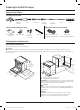
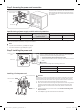
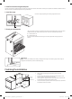
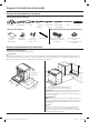
Step 2. Accessing the power cord connection
Terminal block
Access cover
Loosen and then remove the rear access cover screw
with a screwdriver. Remove the rear access cover by
pull right and then out. The terminal block will then
be accessible.
Specied rating of power-supply-cord kit and circuit protection
Range rating, watts Specied rating of power-
supply-cord kit and circuit
protection, Amps
Diameter (inches) of range connection opening
120/240 volts 3-wire 120/208 volts 3-wire Power cord Conduit
8750-16500 7801-12500 40 or 50 A 1
3
⁄8" 1
1
⁄8"
This appliance must be supplied with the proper voltage at the proper frequency and must be connected to a dedicated, properly grounded
branch circuit protected by a 40 amp or larger circuit breaker.
NOTE
• For power cord installations, go to Step 3 on page 4.
• For conduit installations, go to Step 4 on page 5.
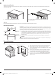
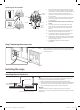
Step 3. Installing the power cord
Conduit connection
plate
Power cord
Strain relief
For power cord installations, hook the strain relief over the power cord
hole (1
3
⁄8") located below the rear of the drawer body. Insert the power
cord through the strain relief and tighten the device.
• You must install the power cord with a strain relief.
• Attach the strain relief to the 1
3
⁄8" opening in the conduit connection
plate.
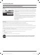
CAUTION
You must check voltage after connecting power cord.
Live 1 - Neutral 120 V
Live 2 - Neutral 120 V
Live 1 - Live 2 208 V / 240 V
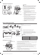
Installing a 3-wire power cord
Neutral terminal
Live 1
Live 2
White
Black
Red
Black White Red
Ground strap
WARNING
The neutral or ground wire of the power cord must be connected to the neutral
terminal located in the center of the terminal block. The power leads must be
connected to the lower left and the lower right terminals of the terminal block.
1. Remove the 3 lower terminal screws from the terminal block.
2. Insert the 3 terminal screws through each power cord terminal ring and into
the lower terminals of the terminal block. Be certain that the center wire
(white/neutral) is connected to the center lower position of the terminal
block.
3. Tighten screws securely to the terminal block. DO NOT remove the ground
strap connection.
4. Go to Step 5 on page 6 to continue with the installation.
DG68-01623A-00_IM_NSE6D_AA_EN+MES.indb 4DG68-01623A-00_IM_NSE6D_AA_EN+MES.indb 4 2024-02-01 오후 6:36:072024-02-01 오후 6:36:07