
Specification

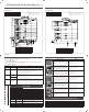

Table Of Contents

electric oven tech sheet
SCHEMATIC DIAGRAM (UPPER OVEN) SCHEMATIC DIAGRAM (LOWER OVEN)
MODEL : NV51K6650D* MODEL : NV51K6650D*
DG68-00858A-00
OTHER COMPONENT TESTS
FIGURE TESTS MEASURE RESULTS
Broil heater
• Measure resistance values of heater’s terminal after
taking off harness from heater.
• Measure voltage of heater’s terminal after making oven
work by pressing broil keypad.
• Approx : 11-15 Ω (at the room temperature)
• Terminal voltage of broil heater : AC 240 V
• Replace or repair harness
• Replace or repair main PCB
Bake heater
• Measure resistance values of heater’s terminal after
taking off harness from heater.
• Measure voltage of heater’s terminal after making oven
work by pressing bake keypad. (Make sure that voltage
has to be measured for more than 1 minute because
heater is supposed to on-off cycling work.)
• Approx : 18-21 Ω (at the room temperature)
• Terminal voltage of bake heater : AC 240 V
• Replace or repair harness
• Replace or repair main PCB
Convection heater
• Measure the resistence values of heater’s terminal after
taking off harness from heater.
• Measure the voltage of heater’s terminal after having
oven worked, by pressing convection bake keypad. (Make
sure that voltage has to be measured for more than 1
minute because heater is supposed to on-off cycling
work.)
• Approx : 40-46 Ω (at the room temperature)
• Terminal voltage of convection heater : AC 240 V
• Replace or repair harness
• Replace or repair main PCB
Steam heater
• Measure resistance values of heater’s terminal after
taking off harness from heater.
• Measure voltage of heater’s terminal after making oven
work by pressing steam bake keypad. (Make sure that
voltage has to be measured for over temperature in
cavity than 215 °F because heater is supposed to on-off
cycling work.)
• Approx : 26-30 Ω (at the room temperature)
• Terminal voltage of steam heater : AC 120 V
• Replace or repair harness
• Replace or repair main PCB
Convection fan
• Measure resistance value of Motor terminal after taking
off harness from Motor.
• Measure Voltage of Motor’s terminal after making oven
work by pressing bake keypad. (Make sure that voltage
has to be measured for more than 1 minute because Fan
is supposed to on-off Cycling work.)
Approx.
• Convection Fan : 20-30 Ω
• Terminal voltage of convection fan : 120 V
• Replace or repair harness
• Replace or repair main PCB
Door lock
• Measure the state of micro switch and motor after taking
off harness from the heater.
• Check whether lock work normally by pressing Control
Lock (3 sec) for 3 seconds.
• Lock motor Resistance : 1600-2200 Ω
(at the room temperature) voltage : 120 V
• Micro switch COM-NC, COM-NO
• Replace or repair if harness has been loosen or
disconnected.
Oven sensor
• Check whether the resistance values of oven sensor is
same with a chart’s one.
• Check whether wire or housing has been loosen or
disconnected.
Approx.
• At the room temperature : 1080 Ω
INFORMATION DISPLAY CODES
Possible check codes during use can be checked before service.
1. Press Clock and number “1, 2, 3, 4” pads.
2. Press START/SET.
3. Press Clock and Touch to Wake-Up/Sleep pads at the same time for 3 seconds. Check codes are displayed.
4. Press number “0” pad, the latest 5 check codes can be checked. But, if the oven turns off, the stored check codes and deleted.
5. Press OVEN OFF pad to return to normal display mode.
DISPLAYED CODE CAUSE SOLUTION
C-d0
This code occurs if
the key short.
1. Check whether cable of keypad has been inserted into connector of sub pcb.
2. Check whether between sub pcb and connector or keypad and cable have a short circuit.
3. If there is not a problem occurred with connector on sub pcb and cable of keypad, replace the sub pcb.
C-d1
This code occurs
if the door lock is
mispositioned.
1. Disconnect power. Open the cover back. Check whether harness has been connected with door lock
switch and motor.
2. Conrm whether resistance value of door lock motor is to be normal one or not.
3. With operating door lockout, measure a voltage of connector on harness which is linked with door
lock motor. (normal voltage : AC 120 V)
4. Check whether door locking switch is being worked normally.
C-20
The oven sensor is
open when the oven
is operating.
1. Check whether connector of main pcb has been inserted.
2. Check whether connector of sensor has been inserted.
3. If there is not a problem occurred with connector on main pcb, replace the sensor.
4. If can’t solve the problem, replace the main pcb.
The oven sensor is
short when the oven
is operating.
C-21
This code occurs
if the internal
temperature rises
abnormally high.
1. Disconnect power. Open the cover back. Disconnect sensor harness from control. Measure sensor
resistance : 1080 Ω at the room temperature. If there are any problems, replace oven sensor.
2. Check the broil, bake and convection heater. Check the resistance of the each heater.
3. Check whether DLB of main pcb, broil, bake and convection heater relay are being worked normally.
4. Check whether there is any disconnection of harness which is linked with main pcb on sub pcb.
5. Check the resistance of oven sensor connector on main pcb. (Normal : 2850 Ω)
WALL MAIN PCB NEW FM PCB
CN100 CN100 This is to supply power with SMPS, and AC 120 with MAIN PCB through harness.
CN200 -
This is connector which have relay of water tank motor and hybrid clean
pump(lower oven) connected.
CN201 - This is connector which have relay of door led connected.
CN203 CN201/CN202
This is connector which have Door lock, oven lamp and relay of connection fan
connected.
CN204 -
This is connector which have relay of water pump, drain pump, and convection
fan connected.
CN300 CN300
This is connector which have Door lock switch, partition switch, Door plunger,
and Water tank inlet switch connected.
CN320 CN320 This is connector which is connected with oven sensor.
CN340/CN500 - This is connector which is connected with steam and steam level sensor.
CN470 CN470 This is connector which is connected with Display PCB to communicate.
CN550 - This is connector which is connected with water tank motor.
DLB RELAY (RY200) DLB RELAY (RY202)
Circuit is designed to have broil relay or convection relay worked after DLB
relay is being worked by Double line break.
(It will not be problem with reversing theorder in inserting Red.)
BROIL RELAY (RY203) BROIL RELAY (RY203)
Broil Relay, Bake Relay, Convection Relay will be on-offworking by mi-com
singnal after DLB relay is worked.
BAKE RELAY (RY204) BAKE RELAY (RY204) Broil relay: It will not be problem with reversing the order in inserting Brown.
CONV. RELAY (RY206) CONV. RELAY (RY206) Bake relay: It will not be problem with reversing the order in inserting Blue.
STEAM RELAY (RY208) - Steam relay: It will not be problem with reversing the order in inserting Brown.
OVEN PCB
Oven sensor resistance (Temperature vs. Sensor resistance), Ro = 1000 Ohms (0 ˚C), RP = 2757 Ohms, Up = 5 V, a = 0.00375
degree F 0 14 23 32 41 50 59 68 77 86 95 104
degree C -17.8 -10 -5 0 5 10 15 20 25 30 35 40
ohms 932.12 961.86 980.95 1000.00 1019.02 1038.02 1056.99 1075.92 1094.83 1113.71 1132.56 1151.38
degree F 113 122 212 302 392 482 572 662 752 842 932 1000
degree C 45 50 100 150 200 250 300 350 400 450 500 538
ohms 1170.17 1188.93 1374.93 1558.01 1738.06 1915.39 2089.69 2261.07 2429.52 2595.05 2757.65 2878.57
OVEN SENSOR OHMMETER TEST
DG68-00858A-00
NOTE: This sheet contains important Technical Service Data.
FOR SERVICE TECHNICIAN ONLY DO NOT REMOVE OR DESTORY
NOTE
1. CIRCUIT SHOWN WITH ALL CONTROL SET TO OFF
2. OVEN DOOR OPENED AND UNLOCKED
3. WATER RESERVOIR INPUTTED AND LOCATED INSIDE
NOTE
1. CIRCUIT SHOWN WITH ALL CONTROL SET TO OFF
2. OVEN DOOR OPENED AND UNLOCKED
3. WATER RESERVOIR INPUTTED AND LOCATED INSIDE
COLOR COLOR COLOR
RED RED BRN BROWN ORG ORANGE
BLK BLACK YEL YELLOW VIO VIOLET
WHT WHITE BLU BLUE GRN GREEN
COLOR COLOR COLOR
RED RED BRN BROWN ORG ORANGE
BLK BLACK YEL YELLOW VIO VIOLET
WHT WHITE BLU BLUE GRN GREEN
HEATING ELECMENTS (UPPER)
COMPONENTS INPUT WATTAGE
BROIL HEATER 240 V 4400 W
BAKE HEATER 240 V 3000 W
CONVECTION HEATER 240 V 1300 W
STEAM HEATER 120 V 500 W
HEATING ELECMENTS (LOWER)
COMPONENTS INPUT WATTAGE
BROIL HEATER 240 V 4400 W
BAKE HEATER 240 V 3000 W
CONVECTION HEATER 240 V 1300 W
NV51K6650D_DG68-00858A-00_EN.indd 1 7/28/2016 3:59:06 PM