
User Manual


20
/ 78
!
WARNING
To avoid risk of electrical shock that can cause death or severe personal injury,
disconnect unit from power before servicing unless tests require power.
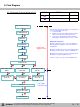
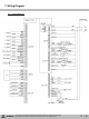
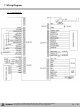
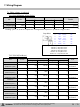
7. Wiring Diagram
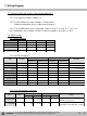
7-3. Other voltage. (continued)
Voltage (V) frequency (Hz) Voltage (V) frequency (Hz)
I/M BOX MOTOR 2,1 10 ~ 12 - 0 -
I/M BOX MOTOR
(Feedback signal)
15 ≒2.5 65~80 0 0
Frequency
fluctuation
C MOTOR 4,3 ≒12 - 0 -
C MOTOR
(PWM frequency)
9 ≒2.5 7000 0 0
C MOTOR
(Feedback signal)
12 ≒2.5 80~95 0 0
Frequency
fluctuation
F MOTOR 6,5 ≒12 - 0 -
F MOTOR
(PWM frequency)
11 ≒3.3 7000 0 0
F MOTOR
(Feedback signal)
14 ≒2.5 45~65 0 0
Frequency
fluctuation
R MOTOR 8,7 ≒12 - 0 -
R MOTOR
(PWM frequency)
10 ≒3.3 7000 0 0
R MOTOR
(Feedback signal)
13 ≒2.5 50~55 0 0
Frequency
fluctuation
비고
Item
Pin No
On
Off
7-3-5. CN 18(Fan Motor)
7-3-4. CN 16(Damper & Step Valve)
Voltage (V) frequency (Hz) Voltage (V) frequency (Hz)
Damper Heater 1 0 - 12 - Floating
Damper Signal 3,4,5,6 6 - 0 - Floating
Step Motor 7,8,9,10 0~12V Swing - 12 - Floating
Item
Pin No
On
Off
Remarks
※ Floating – pins 7, 8, 9, 10 are completed to circuit ground in sequence to operate the stepper valve
Step Motor
CoilPOINT
[Ω]
1-3
Black
Wh/Gray
40Ω
1-5
Black
Yellow
80Ω
3-5
Wh/Gray
Yellow
40Ω
2-4
RED
Wh/Gray
40Ω
2-6
RED
Blue
40Ω
4-6
Wh/Gray
Blue
40Ω
Following is the correct pin for PCB and step motor pin:
PCB Pin 7 = Step Motor Pin 6
PCB Pin 8 = Step Motor Pin 2
PCB Pin 9 = Step Motor Pin 5
PCB Pin 10 = Step Motor Pin 1
PCB Pin 11 = Step Motor Pin 3&4