SyncMaster P64FP P64FT PDP Display User Manual The color and the appearance may differ depending on the product, and the specifications are subject to change without prior notice to improve the performance.
Safety Instructions Notational Note These safety instructions must be followed to ensure your safety and prevent property damage. Make sure to read the instructions carefully and use the product in the correct manner. Warning / Caution Failure to follow directions noted by this symbol could result in bodily harm or damage to the equipment.
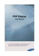
Safety Instructions Do not touch the power plug with wet hands when removing or plugging the plug into the outlet. • Otherwise, this may result in electric shock. Make sure to connect the power cord to a grounded power outlet. • Otherwise, it may result in electric shock or personal injury. Ensure that the power plug is plugged into the power outlet firmly and correctly. • Otherwise, this may result in fire. Do not forcefully bend or pull the power plug and do not place any heavy material on it.
Safety Instructions When installing the product in a cabinet or rack, make sure that the front end of the bottom of the product does not project out. • Otherwise, it may fall or cause personal injury. • Use a cabinet or rack of a size appropriate to the product. DO NOT PLACE CANDLES, MOSQUITO REPELLANT, CIGARETTES AND ANY HEATING APPLIANCES NEAR THE PRODUCT. • Otherwise, this may result in fire. Keep heating appliances as far away from the power cord or the product as possible.
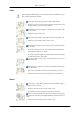
Safety Instructions Clean When cleaning the PDP Display case or the surface of the TFT-PDP screen, wipe with a slightly moistened, soft fabric.. Do not spray cleaner directly onto the surface of the product. • Otherwise, this may result in the discoloration and distortion of the structure and the screen surface may peel off. When cleaning the power plug pins or dusting the power outlet, clean it with a dry cloth. • Otherwise, it may result in fire.
Safety Instructions Do not place this product in a location exposed to moisture, dust, smoke, water, or in a car. • Otherwise, this may result in electric shock or fire. When you drop the product or the case is broken, turn the power off and disconnect the power cord. Contact a Service Center. • Otherwise, this may result in electric shock or fire. If thunder or lightning is occurring, do not touch the power cord or antenna cable. • Otherwise, this may result in electric shock or fire.
Safety Instructions Set a resolution and frequency appropriate to the product. • Otherwise, your eyesight may be damaged. When using headphones or earphones, do not turn the volume too high. • Having the sound too loud may damage your hearing. To avoid eyestrain, do not sit too close to the product. Take a rest for at least five (5) minutes after using the monitor for one (1) hour. • This reduces eye fatigue.
Safety Instructions When replacing the battery, insert it with the right polarity (+, -). • Otherwise, the battery may become damaged or it may cause fire, personal injury or damage due to leakage of the internal liquid. Use only the specified standardized batteries, and do not use a new battery and a used battery at the same time. • Otherwise, the batteries may be damaged or cause fire, personal injury or damage due to a leakage of the internal liquid.
Safety Instructions Do not put any heavy objects on the product. • This may result in personal injury and/or damage to the product.
Introduction Package Contents Note Please make sure the following items are included with your PDP Display. If any items are missing, contact your dealer. Contact a local dealer to buy optional items. Checking the Contents of the Package Remove the lock from the package box, as shown in the figure above. Lift up the package box by holding the grooves on both sides of the package box. Check the contents of the package. Remove the Styrofoam and vinyl cover.
Introduction PDP Display Manuals Quick Setup Guide Warranty Card User's Guide (Not available in all locations) Cables Power Cord D-Sub Cable Remote Control Batteries (AAA X 2) Others Ferrite Core for Power Cord (Not available in all locations) Options (P64FT Model Only) Pen battery charger USB Dongle Adapter Power Cord Zigbee Touch Pen(IWB-P1) Samsung Interactive whiteboard
Introduction Pen battery charger(IWB-C1), USB Dongle(IWB-D1), Zigbee Touch Pen(IWB-P1) only in P64FT model Note This equipment has been tested and found to comply with the limits for a Class B digital device, pursuant to part 15 of the FCC Rules. These limits are designed to provide reasonable protection against harmful interference in a residential installation.
Introduction Sold separately HDMI Cable BNC-COMPONENT Cable COMPOSIT Cable HDMI-DVI Cable Warning • The network box is not compatible with the Interactive Whiteboard program. Ferrite Core • The ferrite cores are used to shield the cables from interference. • When connecting a cable, open the ferrite core and clip it around the cable near the plug. Your PDP Display Note The PDP device may interfere with an amateur radio or AM radio.
Introduction [PC] → [DVI] → [AV] → [HDMI] → [MagicInfo] → [Component] → [BNC] Enter button [ ] Activates a highlighted menu item. Note • This product is not compatible with MagicInfo. MENU button [MENU] Opens the on-screen menu and exits from the menu. Also use to exit the OSD menu or return to the previous menu. - VOL+ Moves from one menu item to another horizontally or adjusts selected menu values. When OSD is not on the screen, push the button to adjust volume.
Introduction POWER IN The power cord plugs into the PDP Display and the wall plug. RS232C OUT/IN (RS232C Serial PORT) MDC(Multiple Display Control) Program Port RGB IN (PC Connection Terminal (Input)) • Use a D-Sub Cable (15 pin D-Sub) - PC mode (Analog PC) • Connect the RGB IN port on the monitor to the BNC port on the PC using the RGB to BNC cable. DVI IN (PC Video Connection Terminal) Connect the [DVI IN] port on the monitor to the DVI port on the PC using the DVI cable.
Introduction • DVI, HDMI and network signals sent via the [DVI OUT] port are displayed on the second display which has the DVI IN port. AV IN [VIDEO] Connect the [AV IN (VIDEO)] terminal of your monitor to the video output terminal of the external device using a VIDEO cable. AUDIO OUT Headphone/External speaker output terminal. HDMI IN Connect the HDMI terminal at the back of your PDP Display to the HDMI terminal of your digital output device using a HDMI cable. Up to HDMI cable 1.2 can be supported.
Introduction • [G/PB] --> Blue port input • [B/PR] --> Red port input This product has an internal speaker. Remote Control Note The performance of the remote control may be affected by a TV or other electronic device operating near the PDP Display , causing a malfunction due to interference with the frequency. POWER OFF Number Buttons / GUIDE button - VOL + SOURCE D.
Introduction EXIT MagicInfo 1. POWER Turns the product On. 2. OFF Turns the product Off. 3. Number Buttons Used to enter the password during the OSD adjustment or to use MagicInfo. The "-" button is used to select Digital channels. 4. / GUIDE button Electronic Program Guide (EPG) display. Note - This button is disabled for this PDP display. 5. - VOL + Adjusts the audio volume. 6. SOURCE Press this button to switch to MagicInfo or PC mode or a connected external input source. 7. D.
Introduction 13. MTS/DUAL Note - This button is disabled for this PDP display. MTSYou can select MTS (Multichannel Television Stereo) mode. FM Stereo Audio Type MTS/S_Mode Default Mono Mono Manual Change Stereo Mono ↔ Stereo SAP Mono ↔ SAP Mono DUALSTEREO/MONO, DUAL l / DUAL ll and MONO/NICAM MONO/NICAM STEREO can be operated depending on the broadcasting type by using the DUAL button on the remote control while watching TV. 14.
Introduction User Installation Guide Note • Be sure to call an installation expert of Samsung Electronics to install the product. • The warranty becomes invalid if the product is installed by someone other than a professional authorized by Samsung Electronics. • A Samsung Electronics service center can provide details. Tilt Angle and Rotation 1 2 1. The product can be tilted up to 15 degrees from a vertical wall. 2.
Introduction • When installing the product onto a vertical wall, be sure there is a 40 mm space or more behind the product for ventilation, as shown above, and maintain the ambient temperature at 35°C or lower. Note A Samsung Electronics service center can provide details. 2. Embedded Mount guide A : min. 40 mm B : min. 70 mm C : min. 50 mm D : min.
Introduction Mechanical Layout * Unit: mm Installation VESA Bracket • When installing VESA, make sure to comply with the international VESA standards. • Purchasing VESA Bracket and Installation Information : Please contact your nearest SAMSUNG Distributor to place an order. After your order is placed, installation professionals will visit you and install the bracket. • At least 2 persons are needed in order to move the PDP Display.
Introduction Accessories (sold separately) • Dimension with other accessories * Unit: mm Wall Bracket Installation • Contact a technician for installing the wall bracket. • SAMSUNG Electronics is not responsible for any damages to the product or harm to customers when the installation is done by the customer. • This product is for installing on cement walls. The product may not stay in place when installed on plaster or wood.
Introduction To mount the product on the wall bracket The shape of the product may vary depending on the model. (The assemblies of the plastic hanger and the screw are the same) 1. Remove the 4 screws on the back of the product. 2. Insert the screw B into the plastic hanger. Notice • Mount the product on the wall bracket and make sure it is properly fixed to the left and right plastic hangers. • Be careful when installing the product on the bracket as fingers can be caught in the holes.
Introduction A- PDP Display B- Wall Bracket C- Wall Wall Bracket Angle Adjustment Adjust the bracket angle to -2° before installing it on the wall. 1. Fix the product to the wall bracket. 2. Hold the product at the top in the center and pull it forward (direction of the arrow) to adjust the angle. Note You can adjust the bracket angle between -2° and 15°. Make sure to use the top center, and not the left or the right side of the product to adjust the angle.
Introduction Remote Control (RS232C) Cable connections interface RS232C(9 pin) pin TxD(No.2) RxD(No.3) GND(No.
Introduction • Tx 3 <--------- 2 Tx Gnd 5 ---------- 5 Gnd Connecting method Control codes • • • Get control Header command 0xAA command type DATA Length ID CheckSum 0 Set control Header command 0xAA command type ID DATA Length DATA 1 Value CheckSum commanding words No.
Introduction - Every communication will be made in hexadecimals and Checksum is the sum of all remainings. If it exceeds two digits,for example, it is 11+FF+01+01=112, discard the number in the first digit like below. example)PowerOn&ID=0 Header command ID DATA Length DATA 1 CheckSum 0xAA 0x11 1 Power Header command DATA Length DATA 1 0xAA 0x11 1 1 ID 12 If you want to control every mechanism connected with Serial Cable regardless of its ID, set ID part to "0xFE" and send commands.
Introduction 0xAA 0xFF 3 ‘N’ 0x11 ERR ERR : Error code that shows what occurred error is • Volume Control • Function Personal Computer changes volume of TV or Monitor.
Introduction • Set Input Source Header command ID 0xAA DATA Length DATA 1 Input Source 0x14 CheckSum Input Source : Input Source code to be set on TV or Monitor 0x14 PC 0x1E BNC 0x18 DVI 0x0C AV 0x04 S-Video 0x08 Component 0x20 MagicInfo 0x1F DVI_VIDEO 0x30 RF(TV) 0x40 DTV 0x21 HDMI1 0x22 HDMI1_PC 0x23 HDMI2 0x24 HDMI2_PC 0x25 DisplayPort Caution DVI_VIDEO, HDMI1_PC, HDMI2_PC → Get Only In the case of MagicInfo, only possible with models include MagicInfo In the case
Introduction • Screen Mode Control • Function Personal Computer changes "Screen Mode" of TV or Monitor Cannot be controlled when Video Wall is on. Caution Only works with models include TV.
Introduction • • Get Screen Size Status Header command 0xAA 0x19 DATA Length ID CheckSum 0 Ack Header command ID 0xAA 0xFF DATA Length Ack/Nak 3 ‘A’ r-CMD Val1 0x19 Screen Size Check Sum Screen Size : Screen Size of TV or Monitor (Range : 0 ~ 255, Unit : Inch) • Nak Header command 0xAA 0xFF ID DATA Length Ack/Nak r-CMD Val1 3 ‘N’ 0x19 ERR Check Sum ERR : Error code that shows what occurred error is • PIP ON / OFF Control • Function The PC turns the PIP function of a
Introduction PIP : Same as above • Nak Header command 0xAA 0xFF ID DATA Length Ack/Nak r-CMD Val1 3 ‘N’ 0x3C ERR Check Sum ERR : Error code that shows what occurred error is • Auto Adjustment Control (PC, BNC Only) • Function Personal Computer controls PC system screen automatically.
Introduction Does not operate in MagicInfo • • Get Video Wall Mode Header command 0xAA 0x5C DATA Length ID CheckSum 0 Set Video Wall Mode Header command 0xAA 0x5C ID DATA Length DATA 1 Video Wall Mode CheckSum Video Wall Mode : Video Wall Mode code to be set on TV or Monitor 1 : Full 0 : Natural • Ack Header DATA Length command Ack/Nak r-CMD Val1 ID 0xAA 0xFF 3 ‘A’ 0x5C Video Wall Mode DATA Length Ack/Nak r-CMD Val1 3 ‘N’ 0x5C ERR Check Sum Video Wall Mode : same as
Introduction • Set Safety Lock Enable / Disable Header command ID 0xAA DATA Length DATA 1 Safety Lock 0x5D CheckSum Safety Lock : Lock code to be set on TV or Monitor 1 : ON 0 : OFF • Ack Header command ID 0xAA 0xFF DATA Length Ack/Nak r-CMD Val1 3 ‘A’ 0x5D Safety Lock DATA Length Ack/Nak r-CMD Val1 3 ‘N’ 0x5D ERR Check Sum Safety Lock : Same as above • Nak Header command 0xAA 0xFF ID ERR : Error code that shows what occurred error is Check Sum
Connections Connecting a Computer There are several ways to connect the computer to the monitor. Choose one from the following options. Using the D-sub (Analog) connector on the video card. • Connect the D-sub to the 15-pin, [RGB IN] port on the back of your PDP Display and the 15 pin D-sub Port on the computer. Using the DVI (Digital) connector on the video card. • Connect the DVI Cable to the [DVI IN] port on the back of your PDP Display and the DVI port on the computer.
Connections Using the HDMI (digital) output on the graphics card. • Connect the [HDMI IN] port on the PDP Display to the HDMI port on the PC using the HDMI cable. Note When the HDMI cable to the PC, ensure that you select HDMI from both the Source List and Edit Name before selecting PC or DVI device so that normal PC screen and sound can be outputted. Note that sound is only available when connected according to the option that follows. Using the BNC (Analog) connector on the video card.
Connections Connect the audio cable for your PDP Display to the audio port on the back of the PDP Display. Connect the power cord for your PDP Display to the power port on the back of the PDP Display. . Note • Turn on both your computer and the PDP Display. • Contact a local SAMSUNG Electronics Service Center to buy optional items. Using Whiteboard (P64FT Model Only) Note • Whiteboard does not support MagicInfo mode. • A stylus pen may be subject to electromagnetic interference.
Connections 2. Components and Their Functions 2-1. Stylus pen No. Parts Functions 1 Pen tip Enables the stylus pen when the sensor on it is pressed. 2 IR sensor Receives IR signals from the panel. 3 SW1 Performs the right-click command. 4 SW2 Functions as the Page Down key on the keyboard. Another function can be assigned as required. 5 SW3 Functions as the Page Up key on the keyboard. Another function can be assigned as required. 6 SW4 power switch 2-2. Pen Battery Charger No.
Connections 2-3 . Charging a Stylus Pen Battery Note • Apply a ferrite core when you charge a pen battery in the charger. • It is recommended that you use a ferrite core when charging a stylus pen battery to avoid electromagnetic interference. • Before you connect the cable, open the ferrite core and wrap the cable around the ferrite core as shown below.
Connections 3-3. Pairing Stylus Pens with the Monitor To connect dual pens to the monitor, install the drawing program in the provided CD on the PC. Refer to "Installing Whiteboard" for details about how to install the drawing program. • Go to Control Panel and run Samsung Interactive Whiteboard. (Alternatively, click the star icon[ program.
Connections • Click OK. 3-5. Adding Keyboard Commands to Pens Make better use of Whiteboard by adding keyboard commands to pens. 1. Go to Pen Setting > Keyboard in the Samsung Interactive Whiteboard program. 2. Select a button. When the key assignment window appears, press the keyboard key you want to assign. The key will be assigned to the button. 3-6. Right-click Function Press Button 1 on the pen when the pen contacts the PDP screen. The right-click function of a mouse will be performed.
Connections Note • The right-click function does not work unless the pen contacts the PDP screen. 4. Afterimage Burn-in Prevention Note • Afterimages can occur on this product due to the nature of PDP devices and the manufacturer shall not be liable for this issue. • To prevent afterimages, it is recommended that you observe the following instructions when using the product. Instructions • Ensure the same still image is not displayed for long hours.
Connections It is recommended that you activate screen saver for a short period of time before you power off the PC. • Activation of Screen saver after the interactive whiteboard program is closed • If the PC is turned off: Screen saver will be active for a specified time before the PC powers of • If the PC is not turned off: The interactive whiteboard program will be closed only.
Connections 1. Connect an audio cable to the audio output port on the external device and [AV/COMPONENT AUDIO IN[R-AUDIO-L]] port on the monitor, and connect the video output port on the external device to the [AV IN [VIDEO]] port on the monitor. 2. Play the DVD, VCR or Camcorder with a DVD disc or tape inserted. 3. Select AV using the SOURCE button on the front of the PDP display or on the remote. Connecting to a Camcorder 1. Locate the AV output jacks on the camcorder.
Connections Connecting the BNC to BNC cable 1. Connect the [BNC/COMPONENT IN [R/PR, G/Y, B/PB]] ports on the monitor to the BNC port on the external device using the BNC to BNC cable. 2. Select BNC using the SOURCE button on the front of the PDP Display or on the remote control. Connecting Using a DVI Cable 1. Connect between the [DVI OUT] port on the PDP Display and the input port on another monitor using a DVI cable. 2.
Connections Connecting Using a HDMI Cable 1. Connect input devices such as a Blu-Ray/DVD player to the [HDMI IN] terminal of the PDP Display using an HDMI cable. 2. Select HDMI using the SOURCE button on the front of the PDP Display or on the remote control. Note In HDMI mode, only PCM format audio is supported. Connecting a DVD Player 1. Connect a set of audio cables between the [AV/COMPONENT AUDIO IN [R-AUDIO-L]] on the PDP Display and the AUDIO OUT jacks on the DVD player. 2.
Connections Note • Select Component for the connection to a DVD player using the SOURCE button on the front of the PDP Display or on the remote control. • Then, start the DVD Player with a DVD disc inserted. • A component cable is optional. • For an explanation of Component video, consult your DVD manual. Connecting a DTV Set Top (Cable/Satellite) Box 1. Connect a Component cable between the [BNC/COMPONENT IN [R/PR, G/Y, B/PB]] port on the PDP Display and the PR, Y, PB jacks on the Set Top Box.
Connections Connecting to an Audio System 1. Connect a set of audio cables between the AUX L, R jacks on the AUDIO SYSTEM and [AUDIO OUT] on PDP Display.
Using the Software Installing Whiteboard (P64FT Model Only) 1. First, insert the Whiteboard installation CD into the CD-ROM drive. 2. Double-click Whiteboard.exe. 3. Click "Next" in the displayed installation wizard screen. 4. When the "License Agreement" window appears, select "I accept the terms of the license agreement" and click "Next." 5. Select "PC Mode" and click "Next" in the displayed "Setup Type" window. 6. Select "PDP Monitor" and click "Next." 7.
Using the Software 10. The MDC Unified shortcut icon will be created on the desktop after installation. Note • The MDC execution icon may not be displayed depending on the PC system or product specifications. • Press F5 if the execution icon is not displayed. Uninstallation 1. Select Settings > Control Panel on the Start menu and double-click Add/Delete Program. 2. Select MDC Unified from the list and click Change/Remove.
What is MDC? Multiple display control "MDC" is an application that allows you to easily control multiple display devices simultaneously using a PC. Connecting to MDC Using MDC via RS-232C (serial data communications standards) An RS-232C serial cable must be connected to the serial ports on the PC and monitor.
Using MDC via Ethernet Enter the IP for the primary display device and connect the device to the PC. One display device can connect to another using an RS-232C serial cable.
Connection Management Connection management includes the Connection list and Connection list modification options. Connection list – Connection list shows the details of the connections such as connection setting (IP/ COM, Port No, MAC, and Connection Type), connection status, Set ID Range, and detected devices. Each connection can contain a maximum of 100 devices connected in serial daisy-chain fashion.
Auto Set ID Auto Set ID feature assigns a Set ID for all the LFDs connected in daisy-chain of a selected connection. There can be a maximum of 100 LFDs in a connection. The Set ID is assigned sequentially in the daisychain running from 1 to 99, and then finally to Set ID 0. Cloning Using the Cloning feature, you can copy the setting of one LFD and apply it to multiple selected LFDs. You can select specific tab categories or all tab categories for cloning, using the copy setting option window.
Command Retry This feature is used to specify the maximum number of times the MDC command will be retried in case of there being no reply or a corrupted reply from an LFD. The retry count value can be set using the MDC options window. The retry count value must be between 1-10. The default value is 1.
Getting Started with MDC 1 To start the program, click Start 2 Click Add to add a display device. z Programs Samsung MDC Unified. If the connection is established via RS232C, go to Serial and specify the COM Port.
z If the connection is established via Ethernet, enter the IP that was entered for the display device.
Main Screen Layout 1 6 5 4 2 3 1 Menu Bar Change the status of a display device or the properties of the program. 2 Device Category View a list of connected display devices or device groups. 3 Schedule Category View a list of schedules for display devices. 4 Set List Select the display device you want to adjust. 5 Modify the Set List Add, edit, regroup or delete sets. 6 Help Topics Display help topics for the program.
Menus You can power on or off a selected device or change the input source or volume of the device. Choose display devices from the list of sets, and select the Home tab. 1 Home Select an item and change the corresponding setting. Power z On: Power on a selected display. z Off: Power off a selected dis Input Input Source : Change the input source. z Input sources available can vary depending on the Display Device Models. The input source can be changed only for displays that are turned on.
This menu shows a list of display devices which have following errors - fan error, temperature error, brightness sensor error, or lamp error. Select a display device from the list. The Repair button will be enabled. Click the refresh button to refresh the error status of the display device. The recovered display device will disappear from the Fault Device List. Fault Device Alert Display device in which error is detected will be reported by email. Fill in all required fields.
Screen Adjustment The screen settings (contrast, brightness, etc.) can be adjusted. Choose display devices from the list of sets, and select the Picture tab. Custom Select an item and change the corresponding screen setting. z Color and Tint are not available if the input source is PC. z Red, Green, Blue and PC Screen Adjustment are not available if the input source is Video.
Options Dynamic Contrast Adjust the Dynamic Contrast for the selected display device. Gamma Control Change the gamma value for the selected display. Auto Motion Plus This option is used to view dynamic images. z Off: Disable the Auto Motion Plus function. z Clear: Set the level of Auto Motion Plus to clear. This mode is suitable to display vivid images. z Standard: Set the level of Auto Motion Plus to standard. z Smooth: Set the level of Auto Motion Plus to smooth.
Size Picture Size Adjust the screen size for the selected display device. The Detail item will be disabled if Picture Size is set to a mode that does not support detailed configuration. The -/+ buttons can be used to adjust Zoom. The screen can be relocated using the up/down/left/right buttons. Detail You can view details of the selected screen size. PC Screen Adjustment Frequency adjustment or fine-tuning is available by using the -/+ buttons in Coarse or Fine.
Sound Adjustment You can change the sound settings. Choose display devices from the list of sets, and select the Sound tab. The Bass or Treble item will be disabled if the item is not supported by the selected set. Bass Adjust the bass for the selected display. Treble Adjust the treble for the selected display. Balance (L/R) Adjust the volume of the left and right speakers of the selected display device. SRS TS XT Enable or disable the SRS TS XT effect for the selected display device.
System Setup Choose display devices from the list of sets, and select the System tab. Video Wall The Video Wall function can be used to display part of a whole picture or repeat the same picture on each of connected multiple display devices. Video Wall is enabled only when devices are in the group. Video Wall Enable or disable Video Wall. Format Select the format to display the split screen.
H Select the number of horizontal display devices. A maximum of 15 displays can be arranged in a row. A maximum of 6 can be assigned to V if 15 is assigned to H. V Select the number of vertical display devices. A maximum of 15 displays can be arranged in a row. A maximum of 6 can be assigned to V if 15 is assigned to H. Screen Position View the layout of displays (configured by the screen divider) or change the layout as required. Screen Position and Preview are enabled when Video Wall is set to on.
PIP Basic information required to adjust PIP will appear in the menu screen. z PIP will be disabled when Video Wall is ON. z Note that Picture Size is disabled when PIP is ON. PIP Size View the PIP Size of the current display. PIP Source Select a PIP input source. Sound Select Select and enable the sound from either the primary screen or secondary screen. Channel The channel can be changed if PIP Source is TV.
General User Auto Color Automatically adjust the screen colors. Available only in PC mode. Auto Power Set the product to automatically power on. Standby Control Set the standby mode to activate if an input source is not detected. Fan & Temperature Configure the settings required to detect the fan speed and internal temperature for the product's protection. Fan Control Select a method to configure the fan speed. Fan Speed Configure the fan speed.
Security Safety Lock Lock the on-screen menus. To unlock the menus, set Safety Lock to Off. Button Lock Lock the buttons on the display device. To unlock the buttons, set Button Lock to Off. OSD Display Source OSD Select whether to display a message when the Source is changed. Not Optimum Mode OSD Select whether to display a message when a non-compatible mode is selected. No Signal OSD Select whether to display a message when there is no input signal.
Time Clock Set Change the current time on the selected display device according to the time set on a PC. If the time is not set on the display device, null values will be displayed. Timer z On Time: Set the time to power on the selected display device. z Off Time: Set the time to power off the selected display device. z Volume: Specify the volume of the display device when it is powered on by On Time. z Source: Specify the input source of the display device when it is powered on by On Time.
Once: Activate the timer only one time. EveryDay: Activate the timer every day. Mon~Fri: Activate the timer from Monday through Friday. Mon~Sat: Activate the timer on Saturdays and Sundays. Manual: Customize days of the week. The checkboxes to select days of the week below Repeat are enabled only if Manual is selected. Holiday Management Holiday Management allows you to prevent devices that are set to be powered on by the Timer from turning on at a specified date.
Screen Burn Protection Pixel Shift Move the screen slightly at specified time intervals to prevent screen burn-in. Screen Saver This function prevents screen burn-in when the screen of the selected display device is left idle for an extended period of time. z Interval: Set the interval to activate the Screen Saver. z Mode: The Time setting can vary for each Mode.
The Safety Screen function can be used to prevent screen burn-in when a stationary image displays on the screen of a display device for an extended period of time. Lamp Control Lamp Control is used to adjust the backlight to reduce power consumption. Automatically adjust the backlight of the selected display device at a specified time. If Manual Lamp Control is adjusted, Auto Lamp Control will automatically switch to Off. Manually adjust the backlight for the selected display.
2 Reset Reset Picture Reset the screen settings. Reset Sound Reset the sound settings. Reset System Reset the system settings. Reset All Reset the screen, sound and system settings at the same time. 3 Edit Column Select the items you want to display in the list of sets. 4 Information View the program information.
Other Functions Resizing a Window Place the mouse pointer on a corner of the program window. An arrow will appear. Move the arrow to customize the size of the program window.
Group Management Creating Groups Create groups and manage the list of sets on a group basis. Duplicate group names cannot be used. 1 Right-click and select Group>Edit in the display device list section on the left side of the program window. 2 In the Edit Group window displayed, click Add on the sub level or Add on the same level. z Add on the sub level: Create a sub-group under the selected group. z Add on the same level: Create a group on the same level as the selected group.
The Add on the same level button is enabled only if at least one group is created. 3 Enter the group name. Deleting Groups 1 2 3 Select a group name, and click Edit. In the Edit Group window displayed, click Delete. Click Yes. The group will be deleted. Renaming Groups 1 2 3 Select a group name, and click Edit. In the Edit Group window displayed, click Rename. If a cursor appears in the old group name, enter a new group name.
Schedule Management Creating Schedules Create and register a schedule on a group basis. 1 Click All Schedule List in the schedule section on the left side of the program window. The Add button will be enabled in the middle. 2 Click the Add button. The Add Schedule window will appear.
3 Click Add below the Device Group item, and select the group you want to add a schedule to. 4 Select Date&Time/Action and click OK. The schedule will be added and a list of schedules will appear in the set list window. z Device Group: Select a group. z Date&Time z Instant Execution: Run the schedule immediately. Timer Set the date, time and interval to run the schedule. Action: Select a function that will activate at the specified time and interval.
Troubleshooting Guide Issue The display you want to control does not appear on the system information chart. Solution 1. Check the connection of the RS232C cable (check that the cable is properly connected to appropriate serial port). 2. Check that another display with a duplicate ID is not connected. Connecting displays with a duplicate ID can cause the displays not to be shown due to data collision. 3. Check that the display ID is within the range of 0 and 99. (Change the ID using the Display menu.
How display properties are shown when multiple displays are used 1 2 3 When no display is selected: The default value is displayed. When one display is selected: Settings for the selected display are displayed. When two displays are selected (e.g. in sequence of ID 1 andID 3): The settings for ID 1 are displayed before the settings for ID 3. 4 When the All+Select checkbox is checked and all displays are selected: The default settings are displayed.
Adjusting the PDP Display Input Available Modes • PC / DVI / BNC • AV • HDMI • Component Source List Use to select PC, DVI or other external input sources connected to the PDP Display. Use to select the screen of your choice. 1. PC 2. DVI 3. AV 4. HDMI 5. MagicInfo - Enabled when a network box is connected. 6. Component 7. BNC Note • Edit Name The direct button on the remote control is the 'SOURCE' button.
Adjusting the PDP Display Name the input device connected to the input jacks to make your input source selection easier. VCR / DVD / Cable STB / HD STB / Satellite STB / AV Receiver / DVD Receiver / Game / Camcorder / DVD Combo / DHR / PC Note • Set Edit Name to PC when a PC is connected via the HDMI or DVI port. In most other cases, set Edit Name to AV.
Adjusting the PDP Display 1. Entertain High brightness For watching motion pictures such as a DVD or VCR. 2. Internet Medium brightness For working with a mixture of images such as texts and graphics. 3. Text Normal brightness For documentations or works involving heavy text. 4. Custom Although the values are carefully chosen by our engineers, the pre-configured values may not be comfortable to your eyes depending on your taste.
Adjusting the PDP Display The color tones can be changed. 1. Off 2. Cool 3. Normal 4. Warm 5. Custom Note If you set the Color Tone to Cool, Normal, Warm, or Custom, the Color Temp function is disabled. If you set the Color Tone to Off, the Color Control function is disabled. Color Control Adjusts individual Red, Green, Blue color balance. Note If you adjust the picture by using the Color Control function, Color Tone will turn to the Custom mode. Red Green Blue Color Temp. Color Temp.
Adjusting the PDP Display Coarse Removes noise such as vertical stripes. Coarse adjustment may move the screen image area. You may relocate it to the center using the horizontal control menu. Fine Removes noise such as horizontal stripes. If the noise persists even after Fine tuning, repeat it after adjusting the frequency (clock speed). Position 1. H-Position Adjusts the screen location horizontally. 2. V-Position Adjusts the screen location vertically.
Adjusting the PDP Display Selects either On or Off with the signal balance. Signal Control 1. R-Gain 2. G-Gain 3. B-Gain 4. R-Offset 5. G-Offset 6. B-Offset Size The Size can be switched. 1. 16:9 2.
Adjusting the PDP Display • Component Mode The PDP Display has four automatic picture settings ("Dynamic", "Standard", "Movie" and "Custom") that are preset at the factory. Dynamic, Standard, Movie, or Custom can be activated. 1. Dynamic 2. Standard 3. Movie 4. Custom Custom By using the on-screen menus, the contrast and brightness can be changed to your personal preference. Contrast Adjusts the Contrast. Brightness Adjusts the Brightness. Sharpness Adjusts the picture Sharpness.
Adjusting the PDP Display Adds a natural tone to the display. Color Tone The color tones can be changed. The individual Color components are also user adjustable. 1. Off 2. Cool2 3. Cool1 4. Normal 5. Warm1 6. Warm2 Note If you set the Color Tone to Cool2, Cool1, Normal, Warm1, or Warm2, the Color Temp function is disabled. Color Temp. Color temp. is a measure of the 'warmth' of the image colors. Note This function is only enabled if the Color Tone is set to Off.
Adjusting the PDP Display 2. Zoom 1 - Magnifies the size of the picture on the screen. 3. Zoom 2 - Magnifies the size of the picture more than “Zoom 1”. 4. 4:3 - Sets the picture to 4:3 normal mode. 5. Just Scan - Displays the input scenes as they are without any cutoff when HDMI / Component 720p, 1080i, 1080p signals are input. Note • Certain external devices may feed the display an out of spec signal that may cause cutoff even when using the Screen Fit feature.
Adjusting the PDP Display Note • In HDMI mode, this function can be available when the input signal is interlaced scan; it cannot be available with progressive scan signal. 1. Off 2. On Sound Available Modes • PC / DVI / BNC • AV • HDMI • Component Mode The PDP Display has a built-in high fidelity stereo amplifier. 1. Standard Selects Standard for the standard factory settings. 2. Music Selects Music when watching music videos or concerts. 3. Movie Selects Movie when viewing movies. 4.
Adjusting the PDP Display Note • You can hear the sound even when sound value is set to 0. • If you adjust sound using Custom function, Mode will turn to Custom mode. Bass Emphasizes low frequency audio. Treble Emphasizes high frequency audio. Balance Allows you to Adjusts the sound balance between the left and right speakers. Auto Volume Reduces the difference in volume control between broadcasters. 1. Off 2.
Adjusting the PDP Display 1. Off 2. On Setup Available Modes • PC / DVI / BNC • AV • HDMI • Component Language You can choose one of 13 languages. Note The language chosen affects only the language of the OSD. It has no effect on any software running on the computer. Time You can set the time. Clock Set Current Time Setting.
Adjusting the PDP Display Sleep Timer Turns the PDP Display off automatically at certain times. 1. Off 2. 30 3. 60 4. 90 5. 120 6. 150 7. 180 Timer1 / Timer2 / Timer3 You can set the PDP display to automatically turn on or off at a specified time. Note • Only enabled when the clock is set using the Clock Set menu. • The Manual option allows you to select a day of the week.
Adjusting the PDP Display You can register holidays. • Delete Selected You can delete selected holidays. Note • • Only enabled when registered holidays are selected. • More than one holiday can be selected and deleted. Delete All You can delete all the registered holidays. Menu Transparency Change the transparency of the background of the OSD. 1. High 2. Medium 3. Low 4.
Adjusting the PDP Display Safety Lock Change PIN The password can be changed. The preset password for the PDP Display is "0000". Note • If you forgot your password, press the remote buttons INFO + EXIT + MUTE to reset the password to "0000." Lock This is the function that locks the OSD in order to keep the current settings or to prevent others from adjusting the settings. Energy Saving This feature adjusts the power consumption of the unit in order to save energy. 1. Off 2.
Adjusting the PDP Display HDMI Black Level When a DVD or set-top box is connected to your Product via HDMI, it may cause a degradation in the screen quality, such as an increase in the black level, a low contrast, or discoloration, etc., depending on the external device connected. In this case, adjust the screen quality of your TV by configuring the HDMI Black Level. 1. Normal 2.
Adjusting the PDP Display The Format can be selected to see a divided screen. 1. Full Provides a full screen without any margins. 2. Natural Displays a natural image with the original aspect ratio intact. Horizontal Sets how many parts the screen should be divided horizontally. Five adjustment levels: 1, 2, 3, 4, and 5. Vertical Sets how many parts the screen should be divided vertically. Five adjustment levels: 1, 2, 3, 4, and 5. Screen Divider The screen can be divided into several images.
Adjusting the PDP Display • The selection will be set up by pressing a number in the selected mode. Safety Screen The Safety Screen function is used to prevent afterimages that may appear when a still picture is displayed on the screen over a long time. • The Safety Screen function scrolls the screen for the specified period of time. • This function is not available when the power is turned off.
Adjusting the PDP Display Five adjustment levels: 0, 1, 2, 3, and 4. Time Set the time interval for performing the horizontal or vertical movement, respectively. Timer Timer You can set the timer for Screen Burn Protection. If you start the operation to erase any residual image, the operation will be performed for the set period of time and then automatically finish. 1. Off 2. On Mode You can change the Safety Screen Type. 1. Scroll 2. Bar 3. Eraser 4. All White 5.
Adjusting the PDP Display Period Use this function to set the execution period for each mode set in the timer. Time Within the set period of time specify a time for execution. • Mode-Scroll : 1~5 sec • Mode-Bar, Eraser : 10~50 sec • Mode-All White, Pattern : 1, 5, 10, 20 30 min Scroll This function prevents after-images on the screen by moving all the pixels on the PDP according to a pattern.
Adjusting the PDP Display This function prevents after-images on the screen by moving long black and white vertical lines. Eraser This function prevents after-images on the screen by moving a rectangular pattern. All White This function prevents after-images on the screen by changing the color of pixels to white. Use this function when there are remaining after-images or symbols on the screen, especially when you displayed a still image on the screen for a long time.
Adjusting the PDP Display 60Hz, by using this function(Resolution Select), you can have the picture displayed on the screen in the specified resolution. Note Available in PC mode only 1. Off 2. 1024 x 768 3. 1280 x 768 4. 1360 x 768 5. 1366 x 768 Note Selecting the menu is only allowed when the graphics resolution is set to 1024 x 768 @ 60Hz, 1280 x 768 @ 60Hz, 1360 x 768 @ 60Hz or 1366 x 768 @ 60Hz. Power On Adjustment Adjust the Power On time for the screen.
Adjusting the PDP Display Reset Reverts the product settings to factory defaults. The Reset function is only available when PC / DVI is being used. Image Reset Note Available in PC mode only The Reset function is not available when Video Wall is On. Color Reset OSD Rotation OSD Rotate 1. Landscape 2. Portrait Multi Control Available Modes • PC / DVI / BNC • AV • HDMI • Component Multi Control Assigns an individual ID to the SET.
Adjusting the PDP Display • ID Setup Assigns distinctive IDs to the SET. • ID Input Use to select the transmitter functions of the individual SET. Only a SET where the ID corresponds to the transmitter setting becomes activated.
Troubleshooting Self-Test Feature Check Note Check the following items yourself before calling for assistance. Contact a Service Center for problems that you cannot solve by yourself. Self-Test Feature Check 1. Turn off both your computer and the PDP Display. 2. Unplug the video cable from the back of the computer. 3. Turn on the PDP Display.
Troubleshooting • Do not use benzene, thinner or other flammable substances, or a wet cloth. 2) Maintaining the Flat Panel Display Screen. Clean with a soft cloth (cotton flannel) smoothly. • Never use acetone, benzene or thinner. (They may cause flaws or deformation of the screen surface.) • The user will be required to pay costs and related expenses for repairing damages caused. Symptoms and Recommended Actions Note A PDP Display recreates visual signals received from the computer.
Troubleshooting (Refer to Connecting a Computer) Problems related to the Screen Note Problems related to the PDP Display screen and their solutions are listed. Q: The screen is blank and the power indicator is off. A: Ensure that the power cord is firmly connected and the PDP Display is on. (Refer to the Connecting a Computer) Q: "Check Signal Cable" message. A: Ensure that the signal cable is firmly connected to the PC or video sources.
Troubleshooting Q: The color image is distorted by dark shadows. A: Adjust color using Custom under OSD Color Adjustment menu. Q: The color white is poor. A: Adjust color using Custom under OSD Color Adjustment menu. Q: The Power Indicator blinks. A: The PDP Display is currently saving the changes made to the settings to the OSD memory. Q: The screen is blank and the power indicator light blinks every 0.5 or 1 seconds. The PDP Display is using its power management system.
Troubleshooting A: Check if the power cord is securely connected. A: Check if a special fluorescent or neon lamp is on in the vicinity. Q: How can I change the frequency? A: The frequency can be changed by reconfiguring the video card. Q&A Note That video card support can vary, depending on the version of the driver used. (Refer to the computer or the video card manual for details.
Specifications General General Model Name SyncMaster P64FP SyncMaster P64FT PDP Panel Size 64 inches / 162 cm Display Area 1416.96 mm (H) x 797.04 mm (V) Pixel Pitch 0.738 mm (H) x 0.738 mm (V) Synchronization Horizontal 30~81 kHz Vertical 56~75 Hz Display Color 16.77M Resolution Optimum resolution 1920 x 1080 @ 60 Hz Maximum resolution 1920 x 1080 @ 60 Hz Maximum Pixel Clock 165MHz (Analog, Digital) Power Supply This product supports 100 - 240 V.
Specifications Environmental considerations Storage Temperature : -4°F ~ 113°F (-20°C ~ 45°C) Humidity : 5 % ~ 95 %, non-condensing Plug and Play Capability This PDP Display can be installed on any Plug & Play compatible system. The interaction of the PDP Display and the computer systems will provide the best operating conditions and PDP Display settings. In most cases, the PDP Display installation will proceed automatically, unless the user wishes to select alternate settings.
Specifications State Normal Operation Power Consumption 550 watts Power saving Power off mode 2 watts 0 watt (Typical) Note • The actual power consumption may be different from the indicated power consumption if the system condition or settings are changed. • To stop any power consumption, disconnect the power cable on the back. Be sure to disconnect the power if you intend to stay away from home for many hours.
Specifications Horizontal Frequency The time to scan one line connecting the right edge to the left edge of the screen horizontally is called the Horizontal Cycle and the inverse number of the Horizontal Cycle is called the Horizontal Frequency. Unit: kHz Vertical Frequency Like a fluorescent lamp, the screen has to repeat the same image many times per second to display an image to the user. The frequency of this repetition is called the Vertical Frequency or Refresh Rate.
Information For Better Display Adjust the computer resolution and screen injection rate (refresh rate) on the computer as described below to enjoy the best picture quality. You can have an uneven picture quality on screen if the best picture quality is not provided for PDP. • Resolution: 1920 x 1080 • Vertical frequency (refresh rate): 60 Hz PDP panels manufactured by using advanced semiconductor technology with a precision of 1ppm (one millionth) and above is used for this product.
Information Power Off, Screen Saver, or Power Save Mode • Turn the power off for 4 hours after 20 hours in use • Turn the power off for 2 hours after 12 hours in use • Set the Monitor to power off with the PC Display Properties Power Scheme. • Use a Screen saver if possible - Screen saver in one color or a moving image is recommended. Change the Color Information periodically Note Use Two different colors Rotate the Color Information with 2 different colors every 30 minutes.
Information • Use Bright colors with little difference in luminance. - Cycle : Change the characters color and background color every 30 minutes • Every 30 minutes, change the characters with movement. • All area display Moving image together with Logo periodically. - Cycle: Display moving image together with Logo for 60 seconds after 4 hours in use.
Information Note Please check CD's User Guide at "OSD Function", some model's will not available. Apply the Screen Erasing function on Product • Apply the Screen Erasing function - Symptom: 2 Vertical blocks move with erasing the display Note Please check CD's User Guide at "OSD Function", some model's will not available.
Appendix Contact SAMSUNG WORLDWIDE Note If you have any questions or comments relating to Samsung products, please contact the SAMSUNG customer care center. North America U.S.A 1-800-SAMSUNG (726-7864) http://www.samsung.com CANADA 1-800-SAMSUNG (726-7864) http://www.samsung.com/ca http://www.samsung.com/ca_fr (French) MEXICO 01-800-SAMSUNG (726-7864) http://www.samsung.com Latin America ARGENTINA 0800-333-3733 http://www.samsung.com BRAZIL 0800-124-421 http://www.samsung.
Appendix Europe http://www.samsung.com/be_fr (French) BOSNIA 05 133 1999 http://www.samsung.com BULGARIA 07001 33 11 http://www.samsung.com CROATIA 062 SAMSUNG (062 726 7864) http://www.samsung.com CZECH 800 - SAMSUNG (800-726786) http://www.samsung.com DENMARK 70 70 19 70 http://www.samsung.com FINLAND 030 - 6227 515 http://www.samsung.com FRANCE 01 48 63 00 00 http://www.samsung.com GERMANY 01805 - SAMSUNG (726-7864, http://www.samsung.
Appendix Europe http://www.samsung.com/ ch_fr/(French) U.K 0330 SAMSUNG (7267864) http://www.samsung.com EIRE 0818 717100 http://www.samsung.com LITHUANIA 8-800-77777 http://www.samsung.com LATVIA 8000-7267 http://www.samsung.com ESTONIA 800-7267 http://www.samsung.com TURKEY 444 77 11 http://www.samsung.com CIS RUSSIA 8-800-555-55-55 http://www.samsung.com GEORGIA 8-800-555-555 http://www.samsung.com ARMENIA 0-800-05-555 http://www.samsung.
Appendix Asia Pacific PHILIPPINES 1-800-10-SAMSUNG (726-7864) for PLDT http://www.samsung.com 1-800-3-SAMSUNG(726-7864) for Digitel 1-800-8-SAMSUNG(726-7864) for Globe 02-5805777 SINGAPORE 1800-SAMSUNG (726-7864) http://www.samsung.com THAILAND 1800-29-3232 http://www.samsung.com 02-689-3232 TAIWAN 0800-329-999 http://www.samsung.com 0266-026-066 VIETNAM 1 800 588 889 http://www.samsung.com Middle East IRAN 021-8255 http://www.samsung.com OMAN 800-SAMSUNG (726-7864) http://www.samsung.
Appendix Vertical Frequency The screen must be redrawn several times per second in order to create and display an image for the user. The frequency of this repetition per second is called the Vertical Frequency or Refresh Rate. Unit: Hz Example: If the same light repeats itself 60 times per second, this is regarded as 60 Hz. Horizontal Frequency The time to scan one line connecting the right edge to the left edge of the screen horizontally is called the Horizontal Cycle.
Appendix Correct Disposal of This Product (Waste Electrical & Electronic Equipment) - Europe only Household users should contact either the retailer where they purchased this product, or their local government office, for details of where and how they can take these items for environmentally safe recycling. Business users should contact their supplier and check the terms and conditions of the purchase contract.