WASHING MACHINE SWV-1200F/1100F/1000F/800F P1291/P1091/P8091/P6091 SERVICE WASHING MACHINE Manual CONTENTS 1. SPECIFICATIONS 2. OVERVIEW OF THE WASHING MACHINE 3. OVERVIEW OF THE CONTROL PANEL 4. PROCESS TABLE 5. GENERAL REEOR FUNCTION 6. TROUBLE DIAGNOSIS 7. TEST MODE 8. DESIGNATION OF MAIN COMPONENTS 9. PCB SHEMATIC DIAGRAM PCB CIRCUIT DIAGRAM PCB PATTERN DIAGRAM WIRING DIAGRAM 10.ASSEMBLE AND DISASSEMBLE 11.TOOLS FOR DISASSEMBLY AND ASSEMLY 12.
! Caution for the safety during servicing 1. Do not allow the customer to repair the product. ☞ The person may be injured or the product life may be shortened. 2. Execute A/S after unplugging the power supply unit. ☞ Be care of the electric shock. 3. Do not plug several plugs in the same outlet. ☞ It may cause the fire due to overheat. 4. Check the damage, pressing or burning of the power plug or outlet. ☞ Replace it promptly if it has problem.(It may cause the electric shock or fire) 5.
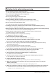
1. Specifications WASH TYPE DIMENSION FRONT LOADING TYPE GROSS W 669mm X D 656mm X H 910mm NET W 598mm X D 550mm X H 844mm WATER PRESSURE WEIGHT 50 kPa ~ 800 kPa GROSS 80 kg NET 75 kg WASHand SPIN CAPACITY POWER CONSUMPTION 5.
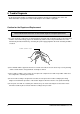
2. Overview of the Washing Machine WATER SUPPLY VALVE CONTROL-PANEL ASSY DOOR DRAWER SENSOR PRESSURE TUB ADJUSTABLE LEG ASSY PUMP HOSE DRAIN(OPTION) CAP DRAIN(OPTION) POWER CORD BUFFER SPRING WEIGHT-BALANCE DRAIN HOSE PULLEY BELT ASSY MOTOR 4 SHOCK ABSORBER SAMSUNG ELECTRONICS CO.
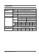
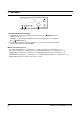
3. Overview of the control panel SWV-1200F/1100F/1000F, P1291/1091 1 2 5 3 4 7 6 8 9 1 2 9 3 4 7 6 8 10 1 2 11 12 3 7 6 8 10 10 SWV-800F/P8091 P6091 1. Detergent dispenser 2. Display panel Displays the remaining wash cycle time, error messages and cancel —. 3. Temperature selection button Press the button repeatedly to cycle through the available water temperature options (cold water, 30°C, 40°C, 60°C and 95°C). 4.
. Course button Press the button repeatedly to select available wash programs 7. Manual button Press the button repeatedly to cycle through the available partial wash options [Wash+Rinse+Spin➔ Prewash+Wash+Spin➔Spin➔Rinse(1 time)+Spin➔ Rinse(2 times)+Spin➔Rinse(3 times)+Spin] in case P6091 [Wash+Rinse+Spin➔ Prewash+Wash+Spin➔Spin➔Rinse(3 times)+Spin] Note : Prewash is only available when washing cotton, synthetic or delicate. 8. Start/Pause button Press to pause and restart programs. 9.
5. General Error Function •· When an error occurs, this function starts to keep generating error melody sounds and displays error indicators as shown in the followings per corresponding error by blinking in 0.5sec interval until the error status is completely cleared out. In this case, all the driving devices are turned off until the error is cleared out. 1.
6. Trouble Diagnosis °· As the micom wash machine is configured of the complicate structure, there might be the service call. Below information is prepared for exact trouble diagnosis and suitable repair guide. Caution for the Repair and Replacement Please follow below instruction for the trouble diagnosis and parts replacement.
6. Trouble Diagnosis No Item 1 The power is not supplied 2 The water is not supplied. 3 The wash does not start though the water supply is stopped. 4 The wash is executed while the water is supplied. The drum does not rotate during washing. 5 6 7 The drum rotates by one direction during washing. (The drum rotates to one direction for SPIN.) Drainage problem. 8 Dehydration problem. 9 Abnormal noise during SPIN. 10 Leak breaker or current/leak breaker is down during washing.
7. Test Mode 1 2 3 1. Driving Compartment Test Mode A. Hold down “2” and ”1” keys simultaneously and then press O(POWER S/W) on. (Display shows “tE”) Hold down “1” and “2” keys simultanesously (each processing for 0.3sec) and then press O(POWER S/W) on. B. The driving compartment can be tested when you press “3” key right after entering into the intial stage of the TEST MODE. ■ Driving Compartment Test Pre-wash VALVE ON(0.3sec) ➔ OFF(0.3sec) ➔ Main wash(0.3sec) ➔ OFF(0.3sec) ➔ Rinse VALVE ON(0.
8. Designation of Main Components 8-1 Normal / Reverse Revolution of Motor and R. P. M. Control 8 Rotor CW 9 - + CCW 5 Stator coil PROTECTOR (150 C) 10 ROTOR Stator coil MIDDLE-SPEED 5 1 2 3 4 5 6 7 8 9 10 + STATOR 9 TACHO Rotor HIGH-SPEED 8 STATOR 10 5 WASHING MOTOR H STATOR(5.10) STATOR(5.1) ROTOR(8.9) TACHO(3.4) PROTECTOR(6.7) “H”(mm) Code-No Resistance value 1.64 Ω 0.91 Ω 1.9 Ω 42.7 Ω 0 52 DC31-10181A 2.07 Ω 0.90 Ω 2.35 Ω 42.
8-4 ASSY-TUB INNER-BEARING OUT-BEARING A B C OIL-SEAL (unit : mm) TYPE INNER-BEARING(A) OUT-BEARING(B) OIL-SEAL(C) CODE-NO REMARK I ø 30 ø 25 ø 43.9 DC97-00214A SPIN SPEED OVER 1000rpm II ø 20 ø 17 ø 24.3 DC97-00214B SPIN SPEED BELOW 800rpm 8-5 ASSY- FLANGE SHAFT C B A (unit : mm) 12 TYPE (A) (B) (C) CODE-NO REMARK I ø 25 ø 30 ø 44.7 DC97-00216A SPIN SPEED OVER 1000rpm II ø 17 ø 20 ø 25 DC97-00214A SPIN SPEED BELOW 800rpm SAMSUNG ELECTRONICS CO.
9. PCB Schematic Diagram SWV-1200F/100F/1000F/800F, P1291/P1091/P8091 P6091 SAMSUNG ELECTRONICS CO.
9. PCB CIRCUIT DIAGRAM 14 SAMSUNG ELECTRONICS CO.
10. Assemble and Disassemble 1. ASS’Y-COVER TOP 1) Remove two screws fixing the top-cover on back side. 2) Push the top-cover back about 15mm and pull it up. 3) It’s possible to exchange and service the trans former, the pressure-senser, the noise-filter and the water valve. m 15m SCREW 2. FRAME FRONT 1) Remove the top-cover and the ass’y drawer. 2) Remove two screws fixing the control-panel on front side and the screw on right side. 3) Remove the cover-front(L) by using the (-)driver.
10. Assemble and Disassemble 3. BELT 1) Remove the top-cover. 2) Disassemble and assemble the belt. 3) Check the belt is located at center of the motor-pulley. Hook the belt on the motor pulley 1) and place it around the pulley 2). 2 PULLEY BELT 1 MOTOR 4. MOTOR 1) Lay down the washer on left side. 2) Remove the wire housing from the motor. 3) Remove the bolt fixing the motor with the box drive on back side. 4) Remove the motor. Motor Assemble Hole 5.
11. Tools for Disassembly and Assembly NO 1 2 TOOL Box driver 10mm Heater (1) 13mm Motor (1), Balance (5) 17mm 2 holes of each left and right of the shock absorber 19mm 1 Pulley hole Double-ended 10, 13 Replaceable for the box driver. spanner 17, 19mm Since the bolt runs idle when the box driver is used, use the box driver 17mm. 3 Vice pliers Tool to protect the idle and abrasion of the bolt for the box driver.
12.
12. Expolded View and Parts List 13 12 26 25 24 22 10 8 29 9 28 11 27 10 16 17 19 20 21 5 4 6 7 18 3 2 1 20 SAMSUNG ELECTRONICS CO.
12. Expolded View and Parts List NO Code No Q'ty Description Specification 1 DC91-12078A 1 ASSY-WIRE DIAPHRAGM SWF-P12,- 2 DC61-20219A 1 DOOR-DIAPHRAGM EPDM,GRY,SWF-P12 3 DC91-12077A 1 ASSY-CLAMP DIAPHGRAM SWF-P12,- 4 DC60-40138A 2 BOLT-W.MOTOR SM10C,HEX,M8,L62,-,ZPC2(YEL),-,- 5 DC60-60044B 5 WASHER-PLAIN SBC,ID8.4,OD30,T3,-,-,- 6 DC60-60040A 3 WASHER-NYLON -,ID10.
12. Expolded View and Parts List 12 11 1 2 19 25 18 23 21 13 3 14 22 4 27 20 24 26 9 15 28 16 30 17 6 10 5 7 35 36 32 37 33 41 34 39 40 38 22 SAMSUNG ELECTRONICS CO.
12. Expolded View and Parts List NO Code No Q'ty Description Specification 1 1-1 1-2 2 2-1 3 4 5 6 7 9 10 11 12 12-1 13 13-1 14 15 16 16-1 17 18 19 20 21 21-1 22 23 24 25 26 27 28 30 32 33 34 35 36 37 38 39 40 40-1 40-2 41 1 1 1 1 1 2 1 1 1 1 2 1 2 1 1 1 1 6 1 1 1 1 1 3 2 1 1 6 0.
12.
12.