
Laptop User Manual


S3C2440A RISC MICROPROCESSOR THUMB INSTRUCTION SET
4-23
OPERATION
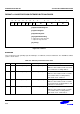
These instructions transfer byte or word values between registers and memory using an immediate 5 or 7-bit
offset. The THUMB assembler syntax is shown in Table 4-10.
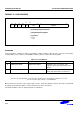
Table 4-10. Summary of Format 9 Instructions
L B THUMB assembler ARM equivalent Description
0 0 STR Rd, [Rb, #Imm] STR Rd, [Rb, #Imm] Calculate the target address by adding
together the value in Rb and Imm. Store
the contents of Rd at the address.
1 0 LDR Rd, [Rb, #Imm] LDR Rd, [Rb, #Imm] Calculate the source address by adding
together the value in Rb and Imm. Load
Rd from the address.
0 1 STRB Rd, [Rb, #Imm] STRB Rd, [Rb, #Imm] Calculate the target address by adding
together the value in Rb and Imm. Store
the byte value in Rd at the address.
1 1 LDRB Rd, [Rb, #Imm] LDRB Rd, [Rb, #Imm] Calculate source address by adding
together the value in Rb and Imm. Load
the byte value at the address into Rd.
NOTE
For word accesses (B = 0), the value specified by #Imm is a full 7-bit address, but must be word-aligned
(ie with bits 1:0 set to 0), since the assembler places #Imm >> 2 in the Offset5 field.
INSTRUCTION CYCLE TIMES
All instructions in this format have an equivalent ARM instruction as shown in Table 4-10. The instruction cycle
times for the THUMB instruction are identical to that of the equivalent ARM instruction.
EXAMPLES
LDR R2, [R5,#116] ; Load into R2 the word found at the address
formed by adding 116 to R5.Note that the
THUMB opcode will contain 29 as the Offset5 value.
STRB R1, [R0,#13] ; Store the lower 8 bits of R1 at the address
formed by adding 13 to R0.Note that the
THUMB opcode will contain 13 as the Offset5 value.