
Laptop User Manual


S3C2440A RISC MICROPROCESSOR THUMB INSTRUCTION SET
4-31
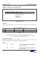
FORMAT 14: PUSH/POP REGISTERS
[7:0] Register List
[8] PC/LR Bit
0 = Do not store LR/Load PC
1 = Store LR/Load PC
[11] Load/Store Bit
0 = Store to memory
1 = Load from memory
15 0
1
14
10
01
13 12
11
Rlist
1 L 0
78
9
1R
Figure 4-15. Format 14
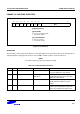
OPERATION
The instructions in this group allow registers 0-7 and optionally LR to be pushed onto the stack, and registers 0-7
and optionally PC to be popped off the stack. The THUMB assembler syntax is shown in Table 4-15.
NOTE
The stack is always assumed to be Full Descending.
Table 4-15. PUSH and POP Instructions
L B THUMB assembler ARM equivalent Description
0 0 PUSH { Rlist } STMDB R13!, { Rlist } Push the registers specified by Rlist onto
the stack. Update the stack pointer.
0 1 PUSH { Rlist, LR } STMDB R13!,
{ Rlist, R14 }
Push the Link Register and the registers
specified by Rlist (if any) onto the stack.
Update the stack pointer.
1 0 POP { Rlist } LDMIA R13!, { Rlist } Pop values off the stack into the registers
specified by Rlist. Update the stack
pointer.
1 1 POP { Rlist, PC } LDMIA R13!, {Rlist, R15} Pop values off the stack and load into the
registers specified by Rlist. Pop the PC
off the stack. Update the stack pointer.