
Laptop User Manual


S3C2440A RISC MICROPROCESSOR NAND FLASH CONTROLLER
6-3
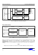
PIN CONFIGURATION
OM[1:0] = 00: Enable NAND flash memory boot
NCON : NAND flash memory selection(Normal / Advance)
0: Normal NAND flash(256Words/512Bytes page size, 3/4 address cycle)
1: Advance NAND flash(1KWords/2KBytes page size, 4/5 address cycle)
GPG13 : NAND flash memory page capacitance selection
0: Page=256Words(NCON = 0) or Page=1KWords(NCON = 1)
1: Page=512Bytes(NCON = 0) or Page=2KBytes(NCON = 1)
GPG14: NAND flash memory address cycle selection
0: 3 address cycle(NCON = 0) or 4 address cycle(NCON = 1)
1: 4 address cycle(NCON = 0) or 5 address cycle(NCON = 1)
GPG15 : NAND flash memory bus width selection
0: 8-bit bus width
1: 16-bit bus width
NOTE
The configuration pin – NCON, GPG[15:13] – will be fetched during reset.
In normal status, these pins must be set as input so that the pin status is not to be changed, when enters
Sleep mode by software or unexpected cause.
NAND FLASH MEMORY CONFIGURATION TABLE
NCON0 GPG13 GPG14 GPG15
0: 256Words 0: 3-Addr
0: Normal NAND
1: 512Bytes 1: 4-Addr
0: 8-bit bus width
0: 1Kwords 0: 4-Addr
1: Advance NAND
1: 2Kbytes 1: 5-Addr
1: 16-bit bus width
Note
With above 4-bit, Possible total combinations are 16, but not all the value can be used.
Example) Nand flash configuration setting.
Parts Page size/Total size NCON0 GPG13 GPG14] GPG15
K9S1208V0M-xxxx
512Byte / 512Mbit 0 1 1 0
K9K2G16U0M-xxxx
1KW / 2Gbit 1 0 1 1