
Laptop User Manual


S3C2440A RISC MICROPROCESSOR PRODUCT OVERVIEW
1-23
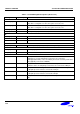
Table 1-3. S3C2440A Signal Descriptions (Sheet 3 of 6)
Signal Input/Output Descriptions
UART
RxD[2:0] I UART receives data input
TxD[2:0] O UART transmits data output
nCTS[1:0] I UART clear to send input signal
nRTS[1:0] O UART request to send output signal
UEXTCLK I External clock input for UART
ADC
AIN[7:0] AI ADC input[7:0]. If it isn’t used pin, it has to be Low (Ground).
Vref AI ADC Vref
IIC-Bus
IICSDA IO IIC-bus data
IICSCL IO IIC-bus clock
IIS-Bus
I2SLRCK IO IIS-bus channel select clock
I2SSDO O IIS-bus serial data output
I2SSDI I IIS-bus serial data input
I2SSCLK IO IIS-bus serial clock
CDCLK O CODEC system clock
AC’97
AC_SYNC
O 48 kHz fixed rate sample sync
AC_BIT_CLK
IO 12.288 MHz serial data clock
AC_nRESET
O AC’97 Master H/W Reset
AC_SDATA_IN
I Serial, time division multiplexed, AC’97 input stream
AC_SDATA_OUT
O Serial, time division multiplexed, AC’97 output stream
Touch Screen
nXPON O Plus X-axis on-off control signal
XMON O Minus X-axis on-off control signal
nYPON O Plus Y-axis on-off control signal
YMON O Minus Y-axis on-off control signal
USB Host
DN[1:0] IO DATA(–) from USB host. (Need to 15K ohm pull-down)
DP[1:0] IO DATA(+) from USB host. (Need to 15K ohm pull-down)
USB Device
PDN0 IO DATA(–) for USB peripheral.
(Need to 470K ohm pull-down for power consumption in sleep mode)
PDP0 IO DATA(+) for USB peripheral. (Need to 1.5K ohm pull-up)