
Laptop User Manual


S3C2440A RISC MICROPROCESSOR I/O PORTS
9-17
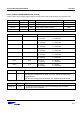
PORT F CONTROL REGISTERS(GPFCON, GPFDAT)
If GPF0 - GPF7 will be used for wake-up signals at power down mode, the ports will be set in interrupt mode.
Register Address R/W Description Reset Value
GPFCON 0x56000050 R/W Configures the pins of port F 0x0
GPFDAT 0x56000054 R/W The data register for port F Undef.
GPFUP 0x56000058 R/W pull-up disable register for port F 0x000
Reserved 0x5600005c - -
GPFCON Bit Description
GPF7 [15:14] 00 = Input 01 = Output
10 = EINT[7] 11 = Reserved
GPF6 [13:12] 00 = Input 01 = Output
10 = EINT[6] 11 = Reserved
GPF5 [11:10] 00 = Input 01 = Output
10 = EINT[5] 11 = Reserved
GPF4 [9:8] 00 = Input 01 = Output
10 = EINT[4] 11 = Reserved
GPF3 [7:6] 00 = Input 01 = Output
10 = EINT[3] 11 = Reserved
GPF2 [5:4] 00 = Input 01 = Output
10 = EINT2] 11 = Reserved
GPF1 [3:2] 00 = Input 01 = Output
10 = EINT[1] 11 = Reserved
GPF0 [1:0] 00 = Input 01 = Output
10 = EINT[0] 11 = Reserved
GPFDAT Bit Description
GPF[7:0] [7:0] When the port is configured as an input port, the corresponding bit is the pin state.
When the port is configured as an output port, the pin state is the same as the
corresponding bit.
When the port is configured as functional pin, the undefined value will be read.
GPFUP Bit Description
GPF[7:0] [7:0] 0: the pull up function attached to to the corresponding port pin is enabled.
1: the pull up function is disabled.