
Laptop User Manual


PWM TIMER S3C2440A RISC MICROPROCESSOR
10-6
TIMER OPERATION
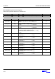
TOUTn
12 46
50 110 4040 6020
3 79 10
5 8 11
Figure 10-4. Example of a Timer Operation
The above Figure 10-4 shows the result of the following procedure:
1. Enable the auto re-load function. Set the TCNTBn to 160 (50+110) and the TCMPBn to 110. Set the manual
update bit and configure the inverter bit (on/off). The manual update bit sets TCNTn and TCMPn to the values
of TCNTBn and TCMPBn, respectively.
And then, set the TCNTBn and the TCMPBn to 80 (40+40) and 40, respectively, to determine the next reload
value.
2. Set the start bit, provided that manual_update is 0 and the inverter is off and auto reload is on. The timer starts
counting down after latency time within the timer resolution.
3. When the TCNTn has the same value as that of the TCMPn, the logic level of the TOUTn is changed from low
to high.
4. When the TCNTn reaches 0, the interrupt request is generated and TCNTBn value is loaded into a temporary
register. At the next timer tick, the TCNTn is reloaded with the temporary register value (TCNTBn).
5. In Interrupt Service Routine (ISR), the TCNTBn and the TCMPBn are set to 80 (20+60) and 60, respectively,
for the next duration.
6. When the TCNTn has the same value as the TCMPn, the logic level of TOUTn is changed from low to high.
7. When the TCNTn reaches 0, the TCNTn is reloaded automatically with the TCNTBn, triggering an interrupt
request.
8. In Interrupt Service Routine (ISR), auto reload and interrupt request are disabled to stop the timer.
9. When the value of the TCNTn is same as the TCMPn, the logic level of the TOUTn is changed from low to
high.
10. Even when the TCNTn reaches 0, the TCNTn is not any more reloaded and the timer is stopped because auto
reload has been disabled.
11. No more interrupt requests are generated.