
User`s manual


S3F84A5_UM_REV1.10 8-BIT TIMER A/B
11-7
FUNCTION DESCRIPTION
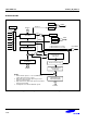
Timer B Interrupts
The timer B module can generate two interrupts: the timer B overflow interrupt (TBOVF), and the timer B match
interrupt (TBINT). TBOVF is interrupt level IRQ1, vector D4H. TBINT also belongs to interrupt level IRQ1, but is
assigned the separate vector address, D6H.
Timer B overflow interrupt can be cleared by both software and hardware, and match interrupt pending conditions
are cleared by software when it has been serviced.
Interval Timer Mode
The timer B module can generate an interrupt: the timer B match interrupt (TBINT). TBINT belongs to interrupt
level IRQ1, and is assigned the separate vector address, D6H.
When timer B interrupt occurs and is serviced by the CPU, the pending condition is cleared by software.
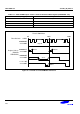
In interval timer mode, a match signal is generated and TBOUT is toggled when the counter value is identical to
the value written to the Timer B reference data register, TBDATA. The match signal generates a timer B match
interrupt(TBINT , vector D6H) and clears the counter.
If, for example, you write the value 10H to TBDATA and 0BH to TBCON, the counter will increment until it reaches
10H. At this point the TBINT interrupt request is generated, the counter value is reset, and counting resumes.
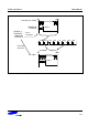
“8+2” Bit Pulse Width Modulation Mode
Pulse width modulation (PWM) mode lets you program the width (duration) of the pulse that is output at the
TBOUT pin. As in interval timer mode, a match signal is generated when the counter value is identical to the value
written to the timer B data register. In PWM mode, however, the match signal does not clear the counter. Instead,
it runs continuously, overflowing at FFH, and then continues incrementing from 00H. The match signal
generates a timer B match interrupt (TBINT , vector D6H). And when the 8-bit counter counts at FFH, a
timer B overflow interrupt(TBOVF, vector D4H) will generate.
Originally the pulse at the TBOUT pin is held to Low level as long as the reference data value is less than or equal
to ( ≤ ) the counter value and then the pulse is held to High level for as long as the data value is greater than ( > )
the counter value. One pulse width is equal to t
CLK
• 256 .
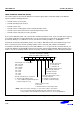
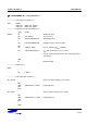
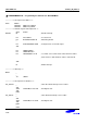
Thanks to the extension logic which is a 2-bit upper counter, Timer B can work in “8+2” bit PWM mode.
To determine the PWM module’s base operating frequency, the lower 8-bit counter is compared to the PWM data
register value. In order to achieve higher resolutions, the 2 bits of the upper counter can be used to modulate the
“stretch” cycle. To control the “stretch” of the PWM output duty cycle at specific intervals, the 2-bit extended
counter value is compared with the 2-bit value (bits 1-0) that you write to the module’s extension register
TBDATAEX. The "stretch" value is one extra clock period at specific intervals, or cycles (see Table 11-1).
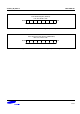
If, for example, the value in the extension TBDATAEX register is “01B”, the 2nd cycle will be one pulse longer
than the other 3 cycles. If the base duty cycle is 50 %, the duty of the 2nd cycle will therefore be "stretched" to
approximately 51% duty. For example, if you write “10B” to the extension data register, all odd-numbered pulses
will be one cycle longer. If you write “11B” to the extension data register, all pulses will be stretched by one cycle
except the 4th pulse. PWM output goes to an output buffer and then to the corresponding PWM output pin. In this
way, you can obtain high output resolution at high frequencies.