
User`s manual


S3F84A5_UM_REV1.10 8-BIT PWM (PULSE WIDTH MODULATION)
13-1
13 8-BIT PWM (PULSE WIDTH MODULATION)
OVERVIEW
This microcontroller’s PWM module has one 8-bit counter and two PWM waveform generation circuits. It is
delicately designed to fit the 3-phase motor control applications.
The PWM module has the following features:
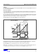
− Two operation modes: edge and center aligned PWM
− Up to six PWM outputs that are internally divided into 2 groups (group A and group B).
− Two group output modes: inverted or non-inverted.
The outputs in each group can be simultaneously set to inverted or non-inverted, thus 3 complementary
outputs is one of the possibilities
− The dead time can be flexibly set by appropriate register setting where 2 registers (PWMADATA and
PWMBDATA) are involved.
− P2PWMOUT register for quick switch from PWM output and normal I/O port output pin
The PWM counter is an 8-bit bi-directional counter. If the counter is stopped, it retains its current count value;
when re-started, it resumes counting from the retained count value. When there is a need to clear the counter you
set PWMCON.1 to "1".
You can select a clock for the PWM counter by set PWMCON.6–.7. Clocks which you can select are f
OSC
/256,
f
OSC
/64, f
OSC
/8, f
OSC
/1.
FUNCTION DESCRIPTION
PWM
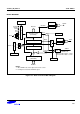
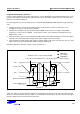
The 8-bit PWM circuits have the following components:
− One 8-bit bi-directional counter
− Two 8-bit comparator circuits
− Two PWM waveform generator circuits: one group uses one waveform generator.
− Two independent 8-bit PWM group buffered compare data registers (PWMADATA, PWMBDATA)
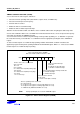
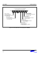
− Six PWM outputs (P2.7/PWM3A, P2.6/PWM3B, P2.4/PWM2A, P2.3/PWM2B, P2.1/PWM1A, P2.0/PWM1B)
− One overflow interrupt. The time the overflow interrupt happens differs in 2 PWM modes.
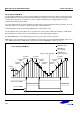
− Two compare match interrupt: group A match and group B match. In center aligned mode, compare match
could happen either in up-counting or down-counting period. You can enable or disable both or one of them
by configuring PWMINT.6-.3.