
Operation Manual


COLOR CCD CAMERA User Guide
18
Installation
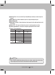
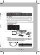
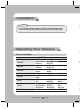
• As shown in the table above, voltage decreases as the wire gets longer.
Therefore use of an excessively long adaptor output line for connection to the
camera may affect the performance of the camera.
Standard voltage for camera operation : DC 12V±10%, AC 24V±10%
There may be some deviation in voltage drop depending on the type of wire and the
manufacturer.
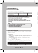
When the resistance value of copper wire is at [20°C(68°F)]
Copper wire size (AWG)
#24(0.22mm
2
) #22(0.33mm
2
) #20(0.52mm
2
) #18(0.83mm
2
)
Resistance (Ω/m)
0.078 0.050 0.030 0.018
Voltage Drop (V/m)
0.028 0.018 0.011 0.006
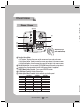
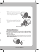
The camera can be controlled by using external controllers like a Remote controller.
(RS-485 Communication)
(1) To control by PC
Connect the RS-485 control port of the camera and the serial cable through an
RS-485 converter.
Control via RS-485 Interface
• Be sure to connect power only after all the installation is complete.
• Note that AC / DC adaptor is not supplied with camera.
• Ground should be connected to the GND terminal.
Notes
*
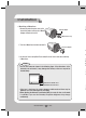
485 Control Board Connection Port RS-485 Control Port
(+) CONNECTION TERMINAL (TRX+) 485+
(- ) CONNECTION TERMINAL (TRX-) 485-
•
•
Example) PC Serial Port (COM1)
Ą
Serial Cable
Ą
RS-485 Converter
Ą
Camera
RS-485Control Port.
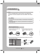
(2) To control using a DVR or System Controller
Connect the RS-485 cable (TRX+, TRX-) to the connection port of the 485 control
board that is connected to the DVR or System Controller.
•