Tantalum Capacitor ( SCL Series ) The SCL series is a slim type of conventional SCS series. Its ability is same as SCS series even though it has thinner thickness that is max. 64% of SCS series. General Features - Environment-Friendly (Pb-free) tantalum capacitor - Low-profile case size - Reduced thickness up to 64% of SCS series - Molded Case available in four case codes. - Compatible with automatic pick and place equipment. - Meets or Exceeds EIA standard 535BAAC .
1 ABBRIVIATION OF TANTALUM CAPACITOR ● 2 TYPE OF SERIES ● The symbol shows the type of the capacitor. SCL : Samsung Capacitor Low-profile series 3 RATED VOLTAGE ● Symbol DC Rated Voltage Symbol DC Rated Voltage 0E 2.5 1C 16 0G 4 1D 20 0J 6.3 1E 25 1A 10 1V 35 4 CAPACITANCE ● Capacitance ( ㎌) PicoFarad ( ㎊) 105 1.0 10×105 684 0.68 68×10 4 106 10.0 10×106 475 4.
7 PACKING ● Symbol Packing Code A 7 inch C 13 inch 8 PACKING POLARITY ● Taping and Reel for Chip Taping and R Reel for Chip Direction of Feed Tape Bulk L B Direction of Feed + Polarity Mark + Polarity Mark SCL Series APPEARANCE AND DIMENSON 0 Code EIA Code DIMENSION (mm) L W1 W2 H Z R 2012-09 2.0 ±0.2 1.25 ±0.2 0.9 ±0.1 0.95max 0.5 ±0.2 S 3216-12 3.2 ±0.2 1.6 ±0.2 1.2 ±0.1 1.2max 0.8 ±0.3 T 3528-12 3.5 ±0.2 2.8 ±0.2 2.2 ±0.1 1.2max 0.8 ±0.3 V 6032-15 6.0 ±0.
● Standard value and Case size Ultra Flat Low Profile Tantalum Chip Capacitors STANDARD VALUE AND CASE SIZE W .V 4V 6.3V 10V 16V Cap.(㎌) (0G) (0J) (1A) (1C) 4.7 475 6.8 685 (S) 10 106 (S) (T) 15 156 22 226 S,T S (S),(T) (T) 33 336 S,T S,T T 47 476 T T (T) 68 686 (T) (T) 100 107 (T) 150 157 ()Under Development New products (2005.01~) are show n in blue.
RELIABILITY TEST CONDITION NO ITEMS TEST CONDITION PERFORMANCE 1 RATED DC VOLTAGE -55℃ ~ +85℃ 2.5∼35V MEASURING FREQUENCY : 120±12Hz 2 CAPACITANCE 3 TANGENT OF LOSS ANGLE CAPACITANCE RANGE MEASURING VOLTAGE : 0.5Vrms + 0.5∼2V DC 0.1∼330㎌ MEASURING CIRCUITS : EQUIVALENT SERIES CIRCUIT TOLERANCE ON CAP. ±10%, ±20% MEASUREMENT SHALL BE MADE UNDER THE SAME CONDITIONS AS THOSE GIVEN FOR THE MEASUREMENT OF CAPACITANCE.
NO ITEMS TEST CONDITION PERFORMANCE THE CAPACITOR SHALL BE SUBJECTED IN TURN TO PROCEDURES SPECIFIED BELOW STEP TEMP. 1 6 CHANGE IN TANGENT OF CAPACITANCE LOSS ANGLE ( ΔC ) (D.F.) WITHIN SPECIFIED TABLE 1 ON 25±2℃ PAGE 13 TOLERANCE TEMPERATURE STABILITY DURATION 2 -55 3 4 5 0 ℃ -3 25±2℃ +85 +3 +125 2 HOURS. +3 0 TABLE 1 ON INITIAL VALUE PAGE 13 0 TO +10% OF TABLE 1 ON INITIAL VALUE PAGE 13 0 TO +12% OF INITIAL VALUE TABLE 1 ON PAGE 13 ℃ 2 HOURS.
NO ITEMS TEST CONDITION PERFORMANCE WHEN OPERATING AT HIGH TEMPERATURE RANGE FROM 85℃ to 125℃, THE OPERATION SHALL BE CARRIED OUT AT A DERATED VOLTAGE OR LESS DERATING VOLTAGE Vt AT ANY TEMPERATURE BETWEEN 85℃ AND 125℃ SHALL BE CALCULATED BY THE FOLLOWING EQUATION VOLTAGE DERATING % 100 80 60 40 8 DERATING 20 VOLTAGE 0 -55 0 20 85 125 OPERATING TEMPERATURE = Vr − Vr − Vd (T − 85) 40 WHERE Vt : DERATED VOLTAGE AT ANY TEMP.
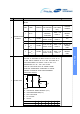
NO ITEMS TEST CONDITION PERFORMANCE A STATIC LAOD OF 19.6N USING A R0.5 SCRATCH THERE SHALL BE NO TOLL SHALL BE APPLIED ON THE CORE OF THE EVIDENCE OF COMPONENT AND IN THE DIRECTION OF THE ARROW MECHANICAL DAMAGE. AND HOLD FOR 5 SEC. THE TEST BOARD SHALL BE ELECTRICAL IEC 40(S)541. HOWEVER THE BASE MATERIAL SHALL CHARACTERISTICS BE G-10 or FR-4 (ANSI GRADE) SHALL SATISFY THE ADHESION 10 Scratch tool (ELECTRODE PEELING Board INITIAL REQUIREMENT. IF THERE ARE ELECTRODES ON BOTH R0.
NO ITEMS TEST CONDITION SOLDER TEMPERATURE : 245±5℃ 12 SOLDERABILITY [Pb-free] DIP TIME : 3±0.5 SEC. SOLDER : Sn-3Ag-0.5Cu FLUX : ROSIN(KSM2951)+Solvent(ISA) PERFORMANCE MORE THAN 95% OF THE TERMINAL SURFACE MUST BE SOLDERED NEWLY. (ROSIN 25WT%) PREHEAT : 100∼110℃ FOR 30 SEC. TEMPERATURE : 260±5℃ ±5% OF INITIAL VALUE DIP TIME : 10 ±1 SEC TANGENT OF LOSS ANGLE : ALL SAMPLES SHALL BE DIPPED IN SOLDER BATH.
NO 16 ITEMS MOISTURE RESISTANCE TEST CONDITION PERFORMANCE THE CAPACITOR SHALL BE STORED AT A CHANGE IN CAPACITANCE : TEMPERATURE OF 40±2℃ AND RELATIVE HUMIDITY OF 90% TO 95% FOR 500±8 HOURS. WITHIN : ±10% OF THE INITIAL VALUE ELECTRICAL MEASUREMENTS SHALL BE MADE TANGENT OF LOSS ANGLE : AFTER BEING BOARD AT ROOM TEMPERATURE FOR 1∼2 HOURS. FOR OTHER PROCEDURES LEAKAGE CURRENT : REFER TO IEC Pub. 68-2-2.
PACKAGING ● MARKING ▶ S CASE A106 Capacitance Code DC Working Voltage (G:4V J:6.
▶ R CASE JA Capacitance Code DC Working Voltage (G:4V J:6.3V A:10V Polarity (White) C:16V D:20V) Capacitance Range 1 DIGIT 2 DIGIT < 1.0 ㎌ A Small Letter A Small Letter 1.0 ㎌≤ Cap.< 10㎌ A Capital Letter A Small Letter ≥ 10 ㎌ A Capital Letter A Capital Letter V 4 6.3 10 16 gj jj aj cj 0.47 gs js as cs ds 0.68 gw jw aw cw dw 1.0 Ga Ja Aa Ca 2.2 Gj Jj Aj Cj 3.3 Gn Jn An 4.7 Gs Js As 6.8 Gw Jw 10 GA JA GJ JJ ㎌ 0.22 20 0.33 1.
● EMBOSSED PLASTIC TAPE Embossed Carrier Right hand Orientation available The tantalum chip capacitors shall be packaged in tape and reel form for effective use. - Tape : Semitransparent embossed plastic - Cover tape : Attached with press, polyester - The tension of removing the cover tape, F=10∼70g Embossed D1 E W F A B P0 P1 P2 K Case Code W±0.3 (±0.01 2) F±0.1 (±0.00 4) E±0.1 (±0.00 4) P O±0.1 (±0.00 4) P1±0.1 (±0.00 4) P2±0.1 (±0.00 4) D1+0.1 (+0.00 4) J* D2Min. t A±0.2 (±0.
● REEL DIMENSION Tape Width ø178 (7) 12mm N Min. ø70 (2.756) ø60 (2.362) C±0.5 (±0.020) ø13 (0.512) D±0.5 (±0.020) B±051 (±0.020) ø21 (0.827) 2 (0.079) 8mm ø330 (13) ø80 (3.150) ø13 (0.512) ø21 (0.827) 12mm Case Size 2 (0.079) 10 (0.394) 14 (0.551) 10 (0.394) 14 (0.551) t+0.5 (±0.020) R 2 (0.079) 0.99 (0.039) 2 (0.079) 0.99 (0.039) 180mm(7") reel 330mm(13") reel J 4,000pcs - R 3,000pcs - S, T 2,000pcs 8,000pcs V, W 500pcs 2,500pcs reference SCL Series 8mm A±2 (±0.
APPLICATION MANUAL The operational attentions to the use of the tantalum capacitors are as follows: - Electrical - Environmental - Conditions for mounting on equipment and circuit boards - Mechanical vibration, shock If the tantalum capacitors are used without satisfying any one of these conditions, the probability of short-circuiting, leakage current, ignition or other problems to occur increases. To avoid such problems, observe the following precautions when using the tantalum capacitors.
● RIPPLE The maximum permissible ripple voltage and current are related to the ratings case size. Please consult us detail in formations. ▶ Ripple Current The maximum permissible ripple current, IMAX, is calculated as follows : PMAX IMAX = ESR(f) where: IMAX : Maximum permissible capacitor ripple current (Arms). PMAX : Maximum permissible capacitor power loss (W). Varies with the ambient temperature and case size. Calculated according to Table ESR(f): Capacitor equivalent series resistance (Ω).
Table.2 Hz VS K 10 Frequency K 120 1.0 400 0.8 1k 0.65 10k 0.50 20k 0.45 40k 0.43 100k 0.40 1M 0.35 1.0 0.1 0.01 100 1K 10K 100K 1M FREQUENCY(Hz) Fig.4 Correction Coefficient(K) ▶ Ripple Voltage If an excessive ripple voltage is applied to the tantalum capacitors, their internal temperature rises due to Joule heat, resulting in the detriment of their reliability.
100 10 100 100 50 V 35 V 25 V 20 V 16 V 10 V 6.3/7 V 4V 2.5 V 10 100 100 100 1 10 100 50 V 35 V 25 V 20 V 16 V 10 V 6.3/7 V 4V 2.5 V 100 100 1 10 100 Frequency(Hz) Frequency(Hz) Fig.6 Maximum permissible ripple voltage Fig.7 Maximum permissible ripple voltage (P,A,B) (C,D) ● REVERSE VOLTAGE ▷ The tantalum capacitors must not be operated and changed in reverse mode. And also the capacitors must not be used in an only AC circuit.
● RELIABILITY OF TANTALUM CAPACITORS ▶ General The failure rate of the tantalum capacitor varies with the digression ratio, ambient temperature, circuit resistance, circuit application, etc. Therefore, when proper selections are made so as to afford additional margins, higher reliability can be derived from the tantalum capacitors. Some examples of actual failure rates are presented below for your reference.
● RELIABILITY PREDICTION Solid tantalum capacitors exhibit no degration failure mode during shelf storage and show a constantly decreasing failure rate(i.e. , absence of wearout mechanism) during life tests. this failure rate is dependent upon three important application conditions:DCvoltage, temperature, and circuit impedance. Estimates of these respective effects are provided by the reliability nomograph.(Figure 8.
Table 4 Circuit Impedance Reliability Factors C ircuit Im pedanc e (ohm s/volt) Failure R ate Im pedanc e (m ultiplying fac tor ) 0.1 1.0 0.2 0.8 0.4 0.6 0.6 0.4 0.8 0.3 1.0 0.2 2.0 0.1 3 or gre ater 0.0 7 ● MOUNTING PRECAUTIONS ▶ Limit Pressure on Capacitor Installation with Mounter A capacitor that has been damaged should be discarded to avoid later problems resulting from mechanical stress. capacitors using an absorber, centering tweezers, or the like.
Table 4 Recommended soldering pattern dimensions(mm) Dimensions Capacitors size Pattern dimensions L W x y z J 1.6 0.85 0.9 1.0 0.7 P 2.0 1.25 1.2 1.1 0.8 S 3.2 1.6 1.6 1.2 1.2 T 3.5 2.8 1.6 2.2 1.4 U 5.8 3.2 2.3 2.4 2.4 V 7.3 4.3 2.3 2.6 3.
▷ Soldering with a soldering iron The use of a soldering iron should be avoided wherever possible. If it is unavoidable, follow the instructions set forth in Table 5. The time of soldering with an iron should be one. Table 5 Soldering-iron tip temperature 350℃ MAX Time 3 sec MAX Soldering-iron power 30 W MAX ▶ Cleaning after Mounting The following solvents are usable when cleaning the capacitors after mounting. Never use a highly active solvent. - Halogen organic solvent (HCFC225, etc.