Smart Dome Camera User Manual Z6806125901A-SCP-2250(P)-ENGLISH1 1 SCP-2250(P) 2010-07-21 오후 6:03:
overview CAUTION RISK OF ELECTRIC SHOCK. DO NOT OPEN CAUTION: TO REDUCE THE RISK OF ELECTRIC SHOCK, DO NOT REMOVE COVER (OR BACK) NO USER SERVICEABLE PARTS INSIDE. REFER SERVICING TO QUALIFIED SERVICE PERSONNEL. This symbol indicates that dangerous voltage consisting a risk of electric shock is present within this unit. This symbol indicates that there are important operating and maintenance instructions in the literature accompanying this unit.
5. When installing the camera, fasten it securely and firmly. The fall of camera may cause personal injury. 6. Do not place conductive objects (e.g. screwdrivers, coins, metal parts, etc.) or containers filled with water on top of the camera. Doing so may cause personal injury due to fire, electric shock, or falling objects. 7. Do not install the unit in humid, dusty, or sooty locations. Doing so may cause fire or electric shock. 9.
overview CAUTION 1. Do not drop objects on the product or apply strong blows to it. Keep away from a location subject to excessive vibration or magnetic interference. 2. Do not install in a location subject to high temperature (over 50°C), low temperature (below -10°C), or high humidity. Doing so may cause fire or electric shock. 3. If you want to relocate the already installed product, be sure to turn off the power and then move or reinstall it. 4.
FCC Statement This device complies with part 15 of the FCC Rules. Operation is subject to the following two conditions : 1) This device may not cause harmful interference, and 2) This device must accept any interference received including interference that may cause undesired operation. This equipment has been tested and found to comply with the limits for a Class A digital device, pursuant to part 15 of FCC Rules.
overview important safety instructions 1. Read these instructions. 2. Keep these instructions. 3. Heed all warnings. 4. Follow all instructions. 5. Do not use this apparatus near water. 6. Clean only with dry cloth. 7. Do not block any ventilation openings. Install in accordance with the manufacturer’s instructions. 8. Do not install near any heat sources such as radiators, heat registers, or other apparatus (including amplifiers) that produce heat. 9.
contents Overview Important Safety Instructions Contents Features What’s Included At a Glance Installation & Connection 10 10 14 17 Preparing Installation Installation Initial Setup Connecting with Other Device Setup 20 21 22 24 33 35 36 38 42 43 45 45 47 48 How to use the Keyboard Controller Main Menu Profile Camera Set Intelligent Video Privacy Zone Preset Auto Set Zone Set Alarm Set Clock Set Other Set Communication System Info 49 50 52 Shortcut Keys Specifications Product Appearance 2 Z680612
overview Features With the state-of-the-art digital signal processing technology, full digital image processing and special algorithm of 600-line high resolution implemented High performance surveillance camera, equipped with x25 zoom lens and digital zoom IC, enabling monitoring up to 400 times DAY/NIGHT to improve the sensitivity by automatic conversion into the black and white mode at night or in the environment with low illumination White Balance to control the brightness to the illumination B
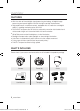
At a Glance CAMERA ● overview HOOK HOOK LENS FRAME SET RS-485 ALARM IN POWER INPUT ALARM OUT M Wipe out a dirty surface of the lens softly with a lens tissue or cloth to which you have applied ethanol.
installation & connection Preparing Installation Use the ceiling installation template when you install the camera on the ceiling on your own. Run the cables through the “” shaped hole on the center of the template, and remove films on the adhesives, and then attach the template on the desired location on the ceiling. When installing the frames set, align all template’s screw holes and those of the frames set. This template prevents dust entering from the ceiling into the camera assembly.
2. Use the three “SCREWS” to fix the “FRAME SET” on a “CAMERA” installation position. FRAME SET SCREW ADAPTOR SCREW 3. Connect external cables to the “CONNECTORS(ALARM IN, POWER, RS-485, ALARM OUT)”and connect the “CONNECTOR” to the “ADAPTOR”. Insert the cable into the “FRAME SET”, and close the “ADAPTOR”.
installation & connection 4. Connect the “SAFETY WIRE” of the “CAMERA” to the “BRACKET WIRE” on the “FRAME SET”. Arrange the “22P CONNECTOR” of the “CAMERA” in line with that of the “ADAPTOR”, push the “HOOK” on either end of the “CAMERA” in the “RACK” direction of the “FRAME SET” to secure the two. Then, ensure that all of the two “HOOKS” “clicks” to fix to the “RACK” properly.
5. Arrange the “COVER” arrow in line with the “FRAME SET” arrow, and push in the “COVER”. Insert the “COVER” to the end, and turn the “COVER” clockwise. As shown in the figure below, turn it until you see the “BUTTON” hole and hear a click. Ensure that the “COVER” should not move any further if you turn the “COVER” counter clockwise.
installation & connection Initial Setup Camera Address Setup Use SW606, SW605, and SW604 to specify the camera address. You can specify between 0 and 255 for the address, where the hundreds digit is with SW606, the tens digit with SW605, and the ones digit with SW604. ex) Camera address: If the address is 1, follow the steps in the figure below. SW606 (x100) SW605 (x10) SW604 (x1) Communication Protocol Setup Use pins #1~#4 of SW603 to specify the communication protocol.
Baud Rate Setup Use pins #5, #6 of SW603 to set the baud rate. PIN 5 PIN 6 4800 BPS ON ON 9600 BPS OFF ON 19200 BPS ON OFF 38400 BPS OFF OFF ● installation & connection BAUD RATE The factory default is 9600 BPS.
installation & connection n < 32 Termination SW1-ON SW2-ON Controller Termination CAM 1 CAM 2 CAM n-1 CAM n M A communication error may occur if you connect multiple cameras that are assigned the same address in the network.
Connecting WITH OTHER device MONITOR POWER SOURCE ALARM OUT ● installation & connection CONTROLLER/DVR ALARM IN Connecting to a monitor 1. Connect one end of the BNC video cable connector to the Video Output Terminal (VIDEO OUT). 2. Connect the other end of the connector to the Video Input Terminal of the monitor.
installation & connection To connect ALARM IN 1. Connect one end of the external device's signal line to a corresponding ALARM IN port of the monitor. 2. Connect the other end of the signal line to the earth-grounding [GND] port. To connect ALARM OUT 1. Connect one end of the external device's signal line to a corresponding ALARM OUT port of the monitor. 2. Connect the other end of the signal line to the common [COM] port.
Connecting the adaptor cable Adaptor Board ● installation & connection Power Supply Connect the cables as necessary, and turn on the camera to check if it works properly. 1. Connect the adaptor to the power terminal of the camera. 2. Plug the power cord of the adaptor into the wall outlet.
setup Connect the camera to the keyboard controller or DVR, with which you can manipulate and change the settings of the camera. How to use the keyboard controller Follow the steps below to set the camera menu using the controller. 1. Open the Camera Setup screen. 2. Use the joystick to navigate through the menus. 3. Press [ENTER] to select a menu item. 4. Use the joystick to change the value of the selected item. 5. Press [ENTER] to apply your changes.
Main Menu This is the first screen you ever see when you turn on the camera where you can set the camera environment to your needs. For selecting and saving each menu item, refer to “How to use the keyboard controller”. (page 20) Z6806125901A-SCP-2250(P)-ENGLISH21 21 ● setup PROFILE MAIN MENU Select a mode appropriate to the camera PROFILE installation environment. CAMERA SET INTELLIGENCE CAMERA SET PRIVACY ZONE PRESET You can configure the camera settings.
setup PROFILE You can select one from the pre-determined configurations as appropriate to your specific camera installation environment. Your selection on each item in PROFILE will affect all other settings of the camera. STANDARD PROFILE Automatically optimizes the camera settings STANDARD to the normal environment. ITS ITS BACKLIGHT DAY/NIGHT This setting enables you to analyze the traffic GAMING situation and take the traffic information at a CUSTOM glance.
CAMERA SETUP MENU Parent Menu Sub-menus XDR STANDARD ITS BACKLIGHT DAY/NIGHT GAMING MEDIUM MEDIUM MEDIUM MEDIUM MEDIUM AUTO AUTO DAY AUTO DAY NIGHT BURST EXT BURST DAY - - - - ON OFF OFF OFF - - - - - OFF ON OFF OFF OFF DAY DAY/NIGHT DAY DAY/NIGHT DAY - - - - - ATW2 ATW1 ATW1 ATW1 ATW1 RED 0 0 0 0 0 BLUE 0 0 0 0 0 MODE WHITE BAL OFF - - - - - MEDIUM Custom Setting MEDIUM Custom Setting ATW2 OFF ATW2 OFF RED Custom Setting 0 Cus
setup CAMERA SET You can configure the general settings of the camera module. For selecting and saving each menu item, refer to “How to use the keyboard controller”. (page 20) 1. Select - . The Camera Setup menu appears. 2. Change the settings as necessary, or select an item to check. CAMERA SET CAMERA ID IRIS MOTION DNR SHUTTER SENS-UP FLICKERLESS XDR OFF ALC (F.
IRIS The IRIS menu is useful if you set to adjust the intensity of radiation incoming to the camera. MANUAL : Adjust the iris level manually. M The overall brightness target of a camera [ 00] ----I---- BACKLIGHT AREA BLC USER ● setup ALC : Adjust the open and close of the iris. - LEVEL : Select an overall brightness level. - BLC : With set to , you can specify the BLC area. With AREA set to , you can specify the position and size.
setup M As long as the DAY/NIGHT menu is set to AUTO in Camera Setup, the AGC menu is not available. As long as FLICKERLESS is set to ON, the FIX mode is not available. MOTION You can specify a level of AGC for controlling the camera motion. This is available only of the SENSE UP menu is set to AUTO. Select F.FAST if you want to monitor a very fast moving object in a low contrast scene, and S.SLOW if monitoring a very slow moving, inanimate object in the same condition.
FLICKERLESS This will prevent possible screen distortion due to a mismatch between the vertical sync frequency and the blinking frequency of the lighting; if set to , the shutter speed will be fixed to 1/100 second. If SHUTTER is set to FIX, SENSE UP to FIX, and AGC to FIX, the menu is not available. This will correct a brightness difference between different scenes for the optimal visibility by calculating the ambient luminance contrast in a certain unit of pixels.
setup - NIGHTDAY DWELL TIME : Time required to determine the filter switch. - MASK AREA : If there exists a bright MASK AREA spot light source in a night scene, you can specify the size and position as needed. This will prevent an error in switching filter, or failure to determine the filter switch in a night scene where a bright spot light source exists. Any excessively bright area in a night scene will be MASKed. You can specify MASK 1 and 2 simultaneously.
WHITE BAL If you need to adjust the color according to the ambient illumination, you can use the function. For selecting and saving each menu item, refer to “How to use the keyboard controller”. (page 20) Illumination is generally referred to as color temperature, which is represented in a measurement of kelvin (K).
setup 1. Select - . 2. Select a mode where you set the . DAY : You can set the RED, and BLUE value in DAY mode. The screen will be displayed in colors DAY/NIGHT according to your settings. MODE You can set the R-GAIN, and B-GAIN value only in mode. If AGC is set to or , the NIGHT WHITE BAL DAY AWC [ 00] ---- I ---[ 00] ---- I ---- RED BLUE R-GAIN B-GAIN [0064] [0064] menu can not be accessed.
FOCUS MODE You can select a focus mode according to the angle that you adjusted for camera recording. - AF : This will monitor the screen continuously to focus automatically. If you adjust the focus manually, that will operate the same as in . This will also restore focus after the operation of pan/tile/zoom. AUTO AF [2] [2] OFF OFF X16 INT ● setup - SENSITIVITY : Indicates the sensitivity of auto focus, which you can adjust between level 1 and level 7.
setup DISPLAY P/T You can set to display the operation status of pan/tilt when it is active. It will disappear in about 3 seconds if the pan/tilt position has no further change. However, the allowable error is ±2°. DIGITAL ZOOM You can set the maximum allowable digital zoom ratio. Digital Zoom will start operation after it is zoomed in to the maximum optical ratio of x25. If you set DIGITAL ZOOM to x16, you can take a shot at up to x400 (25x16).
M If more than one PRIVACY ZONE is specified, and PRIVACY SET to , the PIP function is not available. As long as SENSE UP is set to FIXED, PIP menu is not available. According to the luminance, PIP will disappear if the SENSE UP menu is set to AUTO. DIS (Digital Image Stabilization) M If you set to , the image will be enlarged with digital zoom as much area as compensated. (Approximately 1.
setup ADVANCED You can detect motions and mark the video that contains such motion, and enables tracking of the movement. (The auto PTZ function is not supported for tracking an object.) Selecting the option will mark a region if an existing object disappears, or a new object appears and fixed for a certain period of time. M In following situations, FIXED/MOVED detection may not work properly. - When multiple motions continue arbitrarily.
PRIVACY ZONE You can set up to 12 privacy zones that will be hided for privacy of the subject when recording. Zone Setup For selecting and saving each menu item, refer to “How to use the keyboard controller”. (page 20) 2. Select the number of the zone and press [ENTER]. The Zone setup screen appears. 3. Select the and press [ENTER]. Using the joystick, adjust the camera’s pan, tilt and zoom. 4. Select the . Select the pixel level for the SIZE and LOCATION settings. 5.
setup PRESET This function provides preset camera settings such as pan, tilt, zoom and focus so to enable quicker and easier accessing and monitoring, which supports up to 512 presets. For selecting and saving each menu item, refer to “How to use the keyboard controller”. (page 20) 1. Select -. MAIN MENU PROFILE CAMERA SET INTELLIGENCE PRIVACY ZONE PRESET AUTO SET ZONE SET ALARM SET CLOCK SET OTHER SET 2. Select the preset number.
5. Select and adjust the pan/tilt speed of the preset. 6. Set the that defines the camera's hold duration and of the preset. If you set the to , the video image will be held still until the camera reaches the preset position. For details on setting , and , refer to “CAMERA SET”. (pages 24 ~ 33) M CAMERA SET IRIS WHITE BAL FOCUS MODE ALC MF ● setup 7. Set to .
setup AUTO SET You can set the AUTO PAN, PATTERN, and AUTO PLAY. M If you upload/download the menu setting using SSC-1000, 2000 or 5000, the settings for AUTO PAN, PATTERN, SCAN, and PRESET may differ from the menu settings so define them again after the operation. Auto Pan Setup Set the starting and ending positions to patrol between points at specified speed. For selecting and saving each menu item, refer to “How to use the keyboard controller”. (page 20) 1. Select -.
3. Select each item and set appropriately. POSITION : Set the starting and ending positions for the . Move to the setting screen and adjust pan/tilt to the desired starting position, and then press [ENTER]. Again, adjust pan/tilt to the desired ending position and press [ENTER] to finish setup.
setup 4. Select the and move the camera using pan/tilt/zoom. 5. Your manual camera actions will be recorded for up to 2 minutes, and returns to the previous menu automatically. PATTERN SET 1 START To stop manual recording and return to the previous menu before 2 minutes, press [ENTER]. Scan Setup You can set the SCAN operation to include a defined preset position. For selecting and saving each menu item, refer to “How to use the keyboard controller”. (page 20) 1.
Auto Play Setup AUTO PLAY runs configured AUTO PAN, PATTERN, and SCAN functions automatically. For selecting and saving each menu item, refer to “How to use the keyboard controller”. (page 20) 1. Select -. AUTO PLAY1 : Sets overall function properties of the AUTO PLAY. - AUTO RETURN : Sets the interval between auto plays. - AUTO PLAY : Sets the auto play action at every auto play interval. You can set between 1 ~ 4 for SCAN or AUTO PAN, 1 ~ 3 for PATTERN, and 0 ~ 511 for PRESET.
setup ZONE SET You can set the north direction and the zone coverage. For selecting and saving each menu item, refer to “How to use the keyboard controller”. (page 20) 1. Select -. MAIN MENU PROFILE CAMERA SET INTELLIGENCE PRIVACY ZONE PRESET AUTO SET ZONE SET ALARM SET CLOCK SET OTHER SET 2. Set to . 3. Set the north direction using the joystick and press [ENTER].
ALARM SET It provides 8 alarm inputs and 3 alarm outputs. Detects alarm inputs from the external sensors cooperating with configured presets, patterns, and scan functions, and produces alarm outputs. Alarm’s dwell time is defined by the corresponding preset’s and its alarm action. For selecting and saving each menu item, refer to “How to use the keyboard controller”. (page 20) 1. Select -.
setup ALARM IN SET : Select the alarm sensor AUTO SET operation between , and ALARM1 OFF . ALARM2 OFF ALARM3 OFF ALARM OUT SET : Set the alarm out ALARM4 OFF port matched to the alarm input port. ALARM5 OFF ALARM6 OFF AUTO SET : Sets the pattern and scan ALARM7 OFF action for the corresponding alarm ALARM8 OFF input. When the alarm is generated, the MOTION OFF camera moves to the preset position coupled to the corresponding alarm.
CLOCK SET Sets whether to display the clock on the screen and its time format. For selecting and saving each menu item, refer to “How to use the keyboard controller”. (page 20) 1. Select -. 2. Select and set whether to display the time on the screen. 4. Select the date format and set the date. CLOCK SET OFF 12HOUR AM 07:34:48 MM/DD/YYYY 01/01/2009 ● setup 3. Select the time format and set the clock.
setup Language Select and use the left/right button to select a preferred display language. OTHER SET LANGUAGE FACTORY DEFAULTS OSD COLOR PROPORTIONAL P/T P/T SPEED AUTO CAL. D-FLIP PASSWORD ENGLISH [2] BW ON OFF OFF OFF FACTORY DEFAULTS When selected, the screen appears and you can reset all settings to the factory default settings by selecting the . However, the protocol, baud rate, address and the language settings will not be reset.
AUTO CAL. (AUTO CALIBRATION) To enhance the lens and pan/tilt motor’s accuracy, the automatic compensation function is provided. It automatically resets the lens and pan/tilt when there is no user operation for a specified time period. D-FLIP (DIGITAL FLIP) PASSWORD When selected , it is asked to enter the password for accessing the menu. Select the numbers using direction keys and press [ENTER].
setup SYSTEM INFO You can check the system information. For selecting and saving each menu item, refer to “How to use the keyboard controller”. (page 20) 1. Select -. 2. The current system information is displayed. SYSTEM INFO TYPE PROTOCOL ADDRESS COMM. TYPE BAUD RATE SERIAL NO. CAMERA VER. ALARM VER. 4_PTZ_NOR_P SAMSUNG 0 HW, RS485, HALF 9600 000000000000000 v2.00_100501 v2.
appendix Shortcut Keys ALARM SET OTHER SET AUTO SET Function Key [PRESET] + [5] + [1] + [2] + [ENTER] DAY/NIGHT - NIGHT [PRESET] + [5] + [1] + [3] + [ENTER] DAY/NIGHT - AUTO [PRESET] + [5] + [1] + [4] + [ENTER] DAY/NIGHT - EXT [PRESET] + [5] + [1] + [5] + [ENTER] IRIS - ALC [PRESET] + [5] + [1] + [8] + [ENTER] IRIS - MANU [PRESET] + [5] + [1] + [9] + [ENTER] FOCUS MODE – AF [PRESET] + [5] + [2] + [0] + [ENTER] FOCUS MODE – MF [PRESET] + [5] + [2] + [1] + [ENTER] FOCUS MODE – ONEAF [PRESE
appendix Specifications Item Description Product Type SMART DOME CAMERA Power Source AC 24 V (60 Hz) Power Consumption 11.5W TV Standard NTSC / PAL STANDARD COLOR SYSTEM Image Sensor Super-HAD IT CCD Effective Pixels PAL-752(H) × 582(V) NTSC-768(H) × 494(V) TV line frequency PAL- Horizontal : 15, 625 Hz (INT) / 15, 625 Hz (L/L) Vertical : 50 Hz (INT) / 50 Hz (L/L) NTSC- Horizontal : 15, 734 Hz (INT) / 15, 750 Hz (L/L) Vertical : 59.
Item Description PAN range : 360˚Endless Preset Pan Speed : 600˚/sec, maximum Manual Pan Speed : 0.01˚~ 180˚/sec TILT Tilt range : -6˚~186˚ Preset Tilt Speed : 600˚/sec, maximum Manual Tilt Speed : 0.01˚~ 180˚/sec Remote Control RS485(Half&Full Duplex)/RS422, Data on Coaxial Cable Alarm Alarm Inputs : 8 IN Alarm Outputs : 3 OUT (2 Open collector 1 relay) Operation Temperature -10°C ~ +50°C Operation Humidity ~90% Dimensions (Ø x H) 178 (Ø) x 219(H) mm Weight 1.
appendix Product Appearance 52_ appendix Z6806125901A-SCP-2250(P)-ENGLISH52 52 2010-07-21 오후 6:04:
Correct Disposal of This Product (Waste Electrical & Electronic Equipment) (Applicable in the European Union and other European countries with separate collection systems) This marking on the product, accessories or literature indicates that the product and its electronic accessories (e.g. charger, headset, USB cable) should not be disposed of with other household waste at the end of their working life.
SALES NETWORK SAMSUNG TECHWIN CO., LTD. Samsungtechwin R&D Center, 701, Sampyeong-dong, Bundang-gu, Seongnam-si, Gyeonggi-do, Korea, 463-400 TEL : +82-70-7147-8740~60 FAX : +82-31-8018-3745 SAMSUNG TECHWIN AMERICA Inc. 1480 Charles Willard St, Carson, CA 90746, UNITED STATES Tol Free : +1-877-213-1222 FAX : +1-310-632-2195 www.samsungcctvusa.com www.samsungtechwin.com www.samsungsecurity.com Z6806125901A-SCP-2250(P)-ENGLISH54 54 SAMSUNG TECHWIN EUROPE LTD.