SPEED DOME CAMERA User Manual SCP-2370/SCP-2370H/SCP-2370TH/ SCP-2330/ SCP-2330H/ SCP-2270/SCP-2270H/ SCP-3370/ SCP-3370H/SCP-3370TH
SPEED DOME CAMERA User Manual Copyright ©2011 Samsung Techwin Co., Ltd. All rights reserved. Trademark is the registered logo of Samsung Techwin Co., Ltd. The name of this product is the registered trademark of Samsung Techwin Co., Ltd. Other trademarks mentioned in this manual are the registered trademark of their respective company. Restriction Samsung Techwin Co., Ltd shall reserve the copyright of this document.
safety information CAUTION RISK OF ELECTRIC SHOCK. DO NOT OPEN CAUTION: TO REDUCE THE RISK OF ELECTRIC SHOCK, DO NOT REMOVE COVER (OR BACK) NO USER SERVICEABLE PARTS INSIDE. REFER SERVICING TO QUALIFIED SERVICE PERSONNEL. This symbol indicates that there are important operating and maintenance instructions in the literature accompanying this unit. WARNING • To reduce the risk of fire or electric shock, do not expose this appliance to rain or moisture.
safety information 5. Keep out of direct sunlight and heat radiation sources. It may cause fire. 6. Install it in a place with good ventilation. 7. Avoid aiming the camera directly towards extremely bright objects such as sun, as this may damage the CCD image sensor. 8. Apparatus shall not be exposed to dripping or splashing and no objects filled with liquids, such as vases, shall be placed on the apparatus. 9. Do not expose the camera to radioactivity. Radioactivity exposure may damage the CCD.
important safety instructions 1. Read these instructions. 2. Keep these instructions. 3. Heed all warnings. 4. Follow all instructions. 6. Do not block any ventilation openings. Install in accordance with the manufacturer’s instructions. 7. Do not install near any heat sources such as radiators, heat registers, or other apparatus (including amplifiers) that produce heat. 8. Do not defeat the safety purpose of the polarized or grounding-type plug.
CAUTION These servicing instructions are for use by qualified service personnel only. To reduce the risk of electric shock, do not perform any servicing other than that contained in the operating instructions unless you are qualified to do so. DETAILED WARNINGS AND CAUTIONS y Avoid operating the camera for long durations under high temperatures and in high humidity. Excessive heat can shorten the lifespan of the camera components. y Do not install or place the camera near any heat sources.
6. The speed of the horizontal/vertical rotation will be deteriorated than normal at below -10 degrees for the indoor model, and at below -40 degrees for the environmental model. 7. If the heater malfunctions, a message appears as follows. - "Please Check Heater System" - If this message appears, turn off the camera and call where you bought.
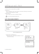
setting up auto track Two different Auto Track setup methods are available. y Using Presets - Select a starting point for Auto Track as a preset to activate Auto Tracking. (This can be used in conjunction with Group SEQ and Tour SEQ.) y Using Target Lock - Select an object on the screen to activate Auto Tracking. M The PIP feature will be disabled if using Auto Track.
2. Selecting Auto Track Starting Point 2 z At Preset Edit, select the preset number under the Preset Settings menu. - The selected preset is indicated with an asterisk (*). - Auto Track : Perform Auto Track upon arrival. Ú For a SCP-3370 series model, select [AutoTrack] from [Intelligence], not from [After Action].
setting up auto track [ Auto Release ] (10sec ~ 5min) Start Tracking [ Lost Mode ] Performed only for the Auto Release duration [ Auto Return ] (1sec ~ 5min) Finish Tracking Initial Location z Auto Release: Command the camera to follow an object for a set duration and then return to its initial (preset) location. z Auto Return : After Auto Release expires, command the camera to stand by at the tracking finish point and then return to its initial location.
5. Auto Tracking Using Group Command z PSET : Using the joystick, enter a preset number under which [After Act.] menu is set to [TRACK]. Group SEQ 1 location. (1 ~ 120sec) z SPD : Adjusts the camera movement speed by 64 different levels.
contents INTRODUCTION 13 CONNECTION & INSTALLATION 18 SETUP 44 TROUBLESHOOTING 13 15 16 17 Features What’s included Component Names and Functions (Indoor Model) Component Names and Functions 18 19 21 22 25 33 34 35 36 39 42 Camera Wiring Interface Board Camera and Appliances Wiring Diagram How to Set Up Protocols and ID DIP Switches Communication Protocol DIP Switch Settings (SW2) Camera ID DIP Switch Settings (SW1) Preparing Adapter and Cables Product Configurations Preparing & Installing Camera Br
introduction FEATURES y A/F 37x/33x/27x Optical Zoom The built-in 37x / 33x / 27x optical zoom lens with auto-focus is combined with a 16x digital zoom, providing a maximum of 592/528/432 zoom. y Wide Range Auto Security Functions - Auto Tracking (SCP-2370TH/SCP3370TH Only) : A moving object or a person can be tracked and recorded automatically by the camera with its Pan, Tilt, and Zoom functions.
introduction y Preset Position Saving and Loading Up to 255 preset positions can be set. Using this function saves and brings up the camera feed of a selected monitoring location. y Camera Backup This is to back up the camera’s sequence information and presets. This is useful when the camera or its install base are damaged or malfunctions occur. y Area Masking If a monitoring location includes a highly private area, the area can be selectively masked on the screen.
WHAT’S INCLUDED Check if the following items are included in the product package.
introduction COMPONENT NAMES AND FUNCTIONS (INDOOR MODEL) Front Back ➊ Bottom ➋ ❶ Unlock Button ❷ SW2: Communication DIP Switch ❸ SW1: ID DIP Switch ➍ Safety Cable Hook ➌ ➍ 16_ introduction
COMPONENT NAMES AND FUNCTIONS Front Back Bottom ➋ ➌ ➊ Safety Wire Holder ➋ SW2: Communication DIP Switch ➌ SW1: ID DIP Switch Ú For the DIP switch settings, please refer to the “Installing Your Camera” on Page 21~25.
connection & installation CAMERA WIRING INTERFACE BOARD For the camera wiring, please refer to the picture below. (When using coaxial communication, a separate control signal connection is not required.) Alarm 2.NC 2.NO 2.COM 7*%&0 IN5 Alarm Input 5~8 % + IN6 */ GND (/% IN7 Alarm Output 2 2.NC */ 2.NO 2.COM */ */ Alarm Output 1 1.NC 1.NO 1.COM IN8 GND IN4 IN3 IN4 Alarm Input 1~4 39 39 59 59 (/%" $0.
CAMERA AND APPLIANCES WIRING DIAGRAM Connecting with Samsung Techwin’s “Stand Alone DVR” Camera RX+ RX- ● CONNECTION & INSTALLATION y RS-485 : Stand Alone DVR T(TXD)+ T(TXD)- y RS-422 : Camera Stand Alone DVR RX+ RX- T(TXD)+ T(TXD)- TX+ TX- R(RXD)+ R(TXD)- Connecting with the Samsung Techwin Controller SPC-6000 y RS-485 : Camera RX+ RX- TXD+ TXD- TX RX + - TX G + - + - RX + - y RS-422 : TX + - Camera RX + - G TX + - RX + - MENU SEARC H MULTI REC MENU PRESE T CAM M
connection & installation To connect to Samsung PC DVR y RS-485 : Camera PC DVR RX+ RX- SRP-1610/1650 20_ connection & installation
HOW TO SET UP PROTOCOLS AND ID DIP SWITCHES You can control various settings of the camera system using the Communication and ID DIP switches. Before installing the product, please set up the DIP switches according to the installation environment. Communication Protocol DIP Switch(SW2) Camera ID DIP Switch(SW1) English - 21 ● CONNECTION & INSTALLATION 1. Detach the camera frame from the install base, and place the bottom of the frame toward you as shown in the picture below. 2.
connection & installation COMMUNICATION PROTOCOL DIP SWITCH SETTINGS (SW2) Coaxial communication automatically detects signals, and so does not require a separate communication setup process. ON ON OFF SW2 SW2 Pin No. Purpose 1~4 Protocol Settings 5~6 Baud Rate Settings 7 Transfer Method (RS-485/422) Settings 8 Response Mode Settings 9~10 Backup Mode Settings 11~12 Termination Settings Protocol Settings Select a communication protocol for the camera.
Baud Rate Settings Select the transfer speed of a selected communication protocol. Baud Rate (BPS) SW2-#5 SW2-#6 1 2,400 ON ON 2 4,800 ON OFF 3 9,600 OFF OFF 4 19,200 OFF ON Communication Method Settings Select a communication method for the camera. SW2- #7 Function Transfer Mode Switch ON RS-422 (4Wire) OFF RS-485 (2Wire) Communication Response Settings Select a communication response method for the camera and controller: Response or No Response.
connection & installation Camera Backup Settings These settings are useful when the camera or its install base are damaged or malfunctions occur. When replacing the camera or its install base, you can transfer existing presets and sequence information to the replacement using these settings. Backup Function SW2- #9 SW2- #10 Backup(IBD) OFF OFF Backup(DIB) ON OFF Backup Disable - ON - Backup(IBD) : Enables transferring the current camera's sequence information to a new camera.
CAMERA ID DIP SWITCH SETTINGS (SW1) Assign a unique number for each camera to identify itself from others. ON ON ● CONNECTION & INSTALLATION OFF SW1 1. The initial value of the switch is “0”, and all of the 8 switches are defaulted to OFF. ON OFF 2. Each switch has a unique value, and the board ID is the sum of the values of the switches. Refer to the example below for the board ID.
connection & installation y Camera ID Chart ID 1 2 3 4 5 6 7 8 9 10 11 12 13 14 15 16 17 18 19 20 21 22 23 24 25 26 27 28 29 30 31 32 33 34 35 36 37 38 SW1-#1 ON/OFF OFF ON OFF ON OFF ON OFF ON OFF ON OFF ON OFF ON OFF ON OFF ON OFF ON OFF ON OFF ON OFF ON OFF ON OFF ON OFF ON OFF ON OFF ON OFF SW1-#2 SW1-#3 SW1-#4 SW1-#5 SW1-#6 SW1-#7 SW1-#8 OFF ON ON OFF OFF ON ON OFF OFF ON ON OFF OFF ON ON OFF OFF ON ON OFF OFF ON ON OFF OFF ON ON OFF OFF ON ON OFF OFF ON ON OFF OFF ON OFF OFF OFF ON ON ON ON
SW1-#1 SW1-#2 SW1-#3 SW1-#4 SW1-#5 SW1-#6 SW1-#7 SW1-#8 ON OFF ON OFF ON OFF ON OFF ON OFF ON OFF ON OFF ON OFF ON OFF ON OFF ON OFF ON OFF ON OFF ON OFF ON OFF ON OFF ON OFF ON OFF ON OFF ON ON OFF OFF ON ON OFF OFF ON ON OFF OFF ON ON OFF OFF ON ON OFF OFF ON ON OFF OFF ON ON OFF OFF ON ON OFF OFF ON ON OFF OFF ON ON OFF OFF ON OFF OFF OFF OFF ON ON ON ON OFF OFF OFF OFF ON ON ON ON OFF OFF OFF OFF ON ON ON ON OFF OFF OFF OFF ON ON ON ON OFF OFF OFF OFF ON ON OFF ON ON ON ON ON ON ON ON OFF OFF
connection & installation ID 78 79 80 81 82 83 84 85 86 87 88 89 90 91 92 93 94 95 96 97 98 99 100 101 102 103 104 105 106 107 108 109 110 111 112 113 114 115 116 SW1-#1 SW1-#2 SW1-#3 SW1-#4 SW1-#5 SW1-#6 OFF ON OFF ON OFF ON OFF ON OFF ON OFF ON OFF ON OFF ON OFF ON OFF ON OFF ON OFF ON OFF ON OFF ON OFF ON OFF ON OFF ON OFF ON OFF ON OFF ON ON OFF OFF ON ON OFF OFF ON ON OFF OFF ON ON OFF OFF ON ON OFF OFF ON ON OFF OFF ON ON OFF OFF ON ON OFF OFF ON ON OFF OFF ON ON OFF ON ON OFF OFF OFF OFF ON
ID SW1-#1 SW1-#2 SW1-#3 SW1-#4 SW1-#5 SW1-#6 SW1-#7 SW1-#8 ON OFF ON OFF ON OFF ON OFF ON OFF ON OFF ON OFF ON OFF ON OFF ON OFF ON OFF ON OFF ON OFF ON OFF ON OFF ON OFF ON OFF ON OFF ON OFF ON OFF ON ON OFF OFF ON ON OFF OFF ON ON OFF OFF ON ON OFF OFF ON ON OFF OFF ON ON OFF OFF ON ON OFF OFF ON ON OFF OFF ON ON OFF OFF ON ON ON ON ON OFF OFF OFF OFF ON ON ON ON OFF OFF OFF OFF ON ON ON ON OFF OFF OFF OFF ON ON ON ON OFF OFF OFF OFF ON ON ON ON OFF OFF OFF OFF OFF OFF OFF ON ON ON ON ON ON ON
connection & installation ID 156 157 158 159 160 161 162 163 164 165 166 167 168 169 170 171 172 173 174 175 176 177 178 179 180 181 182 183 184 185 186 187 188 189 190 191 192 193 194 SW1-#1 SW1-#2 SW1-#3 SW1-#4 SW1-#5 SW1-#6 SW1-#7 OFF ON OFF ON OFF ON OFF ON OFF ON OFF ON OFF ON OFF ON OFF ON OFF ON OFF ON OFF ON OFF ON OFF ON OFF ON OFF ON OFF ON OFF ON OFF ON OFF OFF OFF ON ON OFF OFF ON ON OFF OFF ON ON OFF OFF ON ON OFF OFF ON ON OFF OFF ON ON OFF OFF ON ON OFF OFF ON ON OFF OFF ON ON OFF OF
ID SW1-#1 SW1-#2 SW1-#3 SW1-#4 SW1-#5 SW1-#6 ON OFF ON OFF ON OFF ON OFF ON OFF ON OFF ON OFF ON OFF ON OFF ON OFF ON OFF ON OFF ON OFF ON OFF ON OFF ON OFF ON OFF ON OFF ON OFF ON ON OFF OFF ON ON OFF OFF ON ON OFF OFF ON ON OFF OFF ON ON OFF OFF ON ON OFF OFF ON ON OFF OFF ON ON OFF OFF ON ON OFF OFF ON ON OFF OFF OFF ON ON ON ON OFF OFF OFF OFF ON ON ON ON OFF OFF OFF OFF ON ON ON ON OFF OFF OFF OFF ON ON ON ON OFF OFF OFF OFF ON ON ON ON OFF OFF OFF OFF OFF OFF OFF ON ON ON ON ON ON ON ON OFF
connection & installation ID 234 235 236 237 238 239 240 241 242 243 244 245 246 247 248 249 250 251 252 253 254 255 SW1-#1 SW1-#2 SW1-#3 SW1-#4 SW1-#5 OFF ON OFF ON OFF ON OFF ON OFF ON OFF ON OFF ON OFF ON OFF ON OFF ON OFF ON ON ON OFF OFF ON ON OFF OFF ON ON OFF OFF ON ON OFF OFF ON ON OFF OFF ON ON OFF OFF ON ON ON ON OFF OFF OFF OFF ON ON ON ON OFF OFF OFF OFF ON ON ON ON ON ON ON ON ON ON OFF OFF OFF OFF OFF OFF OFF OFF ON ON ON ON ON ON ON ON OFF OFF OFF OFF OFF OFF ON ON ON ON ON ON ON ON
PREPARING ADAPTER AND CABLES y Power Adapter Power adapter has the capacity of AC24V 2.5A. Distance Recommended Cable Specification 300m 4C2V(RG-59/U) 450m 5C2V(RG-6/U) 600m 7C2V(RG-11/U) the camera is controlled through coaxial communication, please use a video amp intended for coaxial communications. M IfRegular video amps do not transfer coaxial signals. y Communications Cable For the camera to communicate with the controller, a RS-485/422 communications line is required.
connection & installation PRODUCT CONFIGURATIONS ALARM HDD NETWORK BACKUP REC REC 1 2 5 DVD RECORDER 3 6 7 4 8 9 10 11 12 13 14 15 16 ZOOM FR TELE WIDE MODE AUDI VIEW PRESET USB OPEN/CLOSE RETURN RS-485 SRD Series 1 2 16 .... ALARM HDD NETWORK BACKUP REC REC 1 2 5 DVD RECORDER 3 6 7 4 8 9 10 11 12 13 14 15 16 ZOOM FREEZE BACKUP TELE WIDE VIEW MODE AUDIO ALRAM SEARCH MENU USB OPEN/CLOSE RETURN RS-485 SRD Series 1 ....
PREPARING & INSTALLING CAMERA BRACKET For installation guidelines for brackets and housings, refer to the installation manual that is enclosed with the bracket or housing.
connection & installation OPTIONAL ACCESSORIES FOR INSTALLATION For your easier installation, you can purchase appropriate optional accessories available. 1. If installing the camera on the wall y Wall mount (SBP-300WM1) y Wall mount (SBP-300WM) 2. If installing the camera on the ceiling y Ceiling Mount (SBP-300CM) 3.
4. If installing the wall mount (SBP-300WM/SBP-300WM1) on a corner of the wall y Corner Mount (SBP-300KM) ● CONNECTION & INSTALLATION 5. If installing on a building rooftop y Parapet Mount (SBP-300LM) 6. If installing an indoor model outdoors y Outdoor Housing (SHP-3700H) 7. If installing an indoor model on the ceiling y Flush-Mount Indoor Housing for PTZ Dome Camera (SHP-3700F/STH-370PE) 8.
connection & installation y Bracket Mounting (Indoor Model) Wall mount (SBP-300WM1) Wall mount (SBP-300WM) Ceiling Mount (SBP-300CM) Parapet Mount (SBP-300LM) y Bracket Mounting (Environmental Model) Wall mount (SBP-300WM1) Ceiling Mount (SBP-300CM) 38_ connection & installation Wall mount (SBP-300WM) Parapet Mount (SBP-300LM)
ON-CEILING MOUNT TYPE INSTALLATION EXAMPLE Template Lever y Wiring Terminal Cables Connect the cables to the terminal block on the hinged door. For the location of the wiring pins, please refer to the “Camera Wiring Diagram” on Page 18. Once the wiring is successful, close the hinged door. connect the camera to a power outlet until the installation is complete. Supplying power in the middle of the installation M Domaynotcause fire or damage the product.
connection & installation y Setting Up Camera DIP Switches DIP switches for communication and ID protocols are located on the bottom of the camera. For the switch settings, refer to the dip switch settings of this manual. Protocol (SW2) ID (SW1) y Connecting Camera Safety Cable and Attaching Camera Carefully attach the camera to the mount following the alignment guide marks as shown in the picture. First hook the camera's safety cable on the mount, and then attach the camera.
✽ To attach or detach the camera, refer to the picture. * Attaching the camera: Hold up the camera and push it to the mount as shown in the picture. Push the camera until you hear a “click”. * Detaching the camera: To detach the camera, pull the camera downward while pushing the unlock buttons on the camera upward.
connection & installation EXAMPLE OF INSTALLING AN ENVIRONMENTAL MODEL ❖ Fix the installation base with the bracket 1. Fix the base with the bracket by turning it clockwise. 2. As shown in the picture below, gently press and lift up the handle of the hinged door on the bottom of the installation base. Please refer to the “Camera Wiring Interface Board” on page 18, connect the wires. Knob not connect the camera to a power outlet until the installation is complete.
4. Assemble Camera and Installation Base Assemble the installation base and camera by matching the installation direction guides. ● CONNECTION & INSTALLATION 5. Attach Camera Turn the camera frame counterclockwise until the protrusions on the camera frame and installation base become matched perfectly. 6. Secure Camera and Installation Base As shown in the picture below, secure the installation base and camera using 3 hexagon screws.
setup INTERFACE SYMBOLS y Motion Detection Standby/Operation Display : When in standby mode, the “ if motion is detected. ” in the upper right of the screen blinks and then changes to “ ” y Alarm Input Port Status Display : "①", "②", "③", "④", "⑤", "⑥", "⑦", and "⑧" in the upper right of the screen blink. y Current Alarm Port Display According to Input Alarm Ports(Priority) : Only one of " ➊", " ➋", " ➌", " ➍", " ➎", " ➏", " ➐", " ➑" in the upper right of the screen blinks.
USING AND SETTING THE MENUS OSD (On-screen Display) Indicators Has no submenu ● SETUP Has submenu Camera Setting 偓Zoom/Focus White Balance ----- ------ ATW Operating Your Camera z Panning and Tilting : Use the joystick of the controller or its direction buttons. z Controlling Zoom : Move the joystick clockwise (Tele) or counterclockwise (Wide), or use the zoom buttons. z Accessing Screen Menus: Press the Menu or OSD button on the controller.
setup OSD Menu Chart You can have an overall view of the menu structure. For more information, refer to the applicable page or section in the manual. Zoom/Focus White Balance Exposure Back Light Camera Setting AGC SSNR SSDR Day & Night Others Preset Swing SEQ Group SEQ Sequence Setting Tour SEQ PTZ Trace Auto Run Pan/Tilt Limit Power On Resume Area Setting Area Masking Prop.
CAMERA SETUP Zoom and Focus Settings z Focus Mode z Zoom Tracking Through this menu you can set up the camera’s focus mode when zooming. - Mode y Auto : Auto-focuses when zooming. y Tracking : Focuses manually when zooming. y Off : Disable the focus modes when zooming. (Full manual mode) - Speed y Slow/Medium/Fast : Adjusts the zooming speed. Model Fast Medium Slow 37x (SCP-3370) 2.8 sec 4.0 sec 7.1 sec 37x (SCP-2370) 2.5 sec 3.1 sec 5.6 sec 33x (SCP-2330) 2.2 sec 2.5 sec 4.
setup White Balance The White Balance menu adjusts the balance of the screen colors under different lighting conditions. z ATW : Adjusts the screen color automatically. (Color Temperature:1800~10500°K) z INDOOR : Adjusts the screen color to be optimal in an indoor environment. (Color Temperature:4500~8500°K) z OUTDOOR : Adjusts the screen color to be optimal in an outdoor environment.
Exposure The Exposure settings are to control the camera’s exposure meter. z Brightness : Adjusts the screen brightness. z Iris - AUTO : Automatically adjusts the exposure meter. - MANUAL : Enables manual adjustment of the exposure meter. (F1.6~Close: 18 levels) z Shutter : Controls the camera’s electronic shutter. - --- : The shutter speed is fixed at 1/60 for NTSC and 1/50 for PAL. Operates when Iris is on the Auto Mode. - ESC : Adjusts the shutter speed automatically according to the screen brightness.
setup Back Light The Backlight function is dedicated to SV-V DSP (SCP-3XX0) or W-V DSP (SCP-2XX0) chip, developed by Samsung Techwin, which, unlike the old models, provides a sharp image of both object and background against a severe counter-light condition. z Back Light Mode - OFF : Disables the Backlight mode. - WDR : Activates the Wide Dynamic Range mode. - HLC : Activates the High Light Compensation mode. - BLC : Activates a user defined backlight compensation mode.
- MODE : Select a mode that is suitable to the indoor or outdoor backlight condition. - ANTI ROLLING : Reduces the difference of ambient colors to lessen the rolling that occurs under the fluorescent lighting. M WDR is disabled if the shutter is in Manual mode. During WDR operation, noise, discoloration, spots, and whitish symptoms may occur depending on lighting conditions. If ● SETUP they occur, stop using WDR.
setup BLC Setting You can selectively choose a screen area to see objects within the area more clearly than others. BLC MEDIUM - Four-direction Joystick Controls : Moving the joystick in all four directions—upward, downward, left, and right—adjusts the location and size of a selected area. - Zoom Control : y Zoom Tele : Enlarges the size of a selected area. y Zoom Wide : Reduces the size of a selected area.
SSNR(Samsung Super Noise Reduction) SSNR significantly reduces the amount of low luminance noise. Main Menu Camera Setting Sequence Setting P/T Setting OSD Setting Alarm Setting Initialize Password Setting Status ● SETUP - OFF : Disables the noise reduction function. - LOW : Reduces only a small amount of noise, but generates almost no afterimage. - MEDIUM : The most commonly used mode. Reduces a suitable amount of noise while generating a subtle afterimage.
setup SSDR(Samsung Super Dynamic Range) SSDR illuminates darker spots of an image while retaining the same light level for brighter spots to even out the overall brightness of the image with high contrast between bright and dark spots. SSDR ON Main Menu Camera Setting Sequence Setting P/T Setting OSD Setting Alarm Setting Initialize Password Setting Status SSDR OFF Æ Camera Setting - Mode : Enables or disables SSDR. - Range : Defines a range of SSDR.
Day & Night The Day & Night function allows the camera to switch between the Color and B/W modes. - AUTO : Operates in Color mode most times, and switches to B/W mode if a low light level is detected during nighttime. - COLOR : Operates in Color mode at all times. - B/W : Operates in B/W mode at all times. By using the Burst On/Off sub menu, burst signals can be retained or disabled.
setup Others z Sync : Select Internal or Line Lock (Not applied to SCP-XXXXT). - INTERNAL : Synchronizes the camera’s output timing to the internal crystal. - LINE LOCK : Synchronizes the camera’s output timing to the AC adapter power to synchronize multiple cameras. This option is useful when using a switch such as Matrix Switcher. - LINE LOCK PHASE : Enables setting the adapter’s synchronization phase between 0 and 359°. z Image Adj : - Sharpness : Sharpens outlines of an image.
Sequence Setting Preset z Setting Up Preset Numbers : Selecting the Preset Setting menu brings up a screen as shown below. Move the joystick in all four directions to select the desired number.
setup PTZF Setting 1. If you open the PTZF setup menu, you will see the following window. You can use the joystick to select a desired number. Preset Setting Preset = 001 (1~255) 2. Select a preset number and press ENTER. You will move to the setup screen. Using the joystick, adjust the location of the Pan and Tilt functions and then set the Zoom and Focus command. In Preset Settings, the Zoom and Focus command is controllable only by the Zoom command.
Motion Detection / Intelligence (SCP-3370 Series) This will enable you to detect and trace a moving object. SCP-3370 series support the intelligent motion detection feature. For the compatibility of this feature, refer to the table below.
setup z Tracking : This will detect and trace a moving object. You can use the fence function to count the moving objects. The default setting is the same as in the Detect menu, to which the Fence Position function is added. - Fence : Specify the position and detectable direction of the line fence or area fence, depending on the fence type. - Display: Specify the display of the fence status. - Type : You can select one of two types for the fence LINE and AREA.
Preset Name Setting Using this function, you can add names to preset locations. up to 12 characters. Once a name is entered, use the joystick and the Enter key to perform the Set command and save the name. Main Menu ● SETUP Camera Setting Sequence Setting P/T Setting OSD Setting Alarm Setting Initialize Password Setting Status Æ OSD Setting Camera ID Camera Name Preset Number Preset Name ....
setup Home Position Sets one of the currently configured preset positions as the home position. Execute Preset Setting Edit Home Position Execute Clear Status OFF Preset Recalls a saved preset location. While in Sequence mode operation, the actual movement can be slower than the specified when moving the camera in the direction of Pan and Tilt at the same time. Setting Edit Home Position Execute Clear Status OFF Clear Deletes the selected preset location.
Swing SEQ The Swing function commands the camera to move between 2 selected locations, monitoring the route. Activates the Pan function for the Swing operation. z Tilt Swing : Activates the Tilt function for the Swing operation. z P/T Swing : Activates both the Pan and Tilt functions for the Swing operation. Camera Setting Sequence Setting P/T Setting OSD Setting Alarm Setting Initialize Password Setting Status Æ z Swing Setting/Execute/Clear Each of the Swing menus have sub menus with the settings.
setup Group SEQ Selecting Group SEQ recalls a group of multiple preset locations in a consecutive manner. Up to 6 groups can be defined and up to 128 presets can be memorized for each group. z Setting : Using the joystick,enter desired preset numbers into the PSET section. DWT indicates the camera’s duration of stay at a preset location. The speed is adjusted in 64 levels.
Tour SEQ Selecting Tour SEQ recalls groups of preset locations in a consecutive manner. Up to 6 groups can be listed for this function. Selecting the Settings menu brings up the following screen. Using the joystick, you can enter desired group numbers to the Group section. DWT indicates the camera’s standby time before a new group is recalled. Tour SEQ NO 01: 02: 03: 04: 05: 06: Group * * * * * * DWT(s) 003 003 003 003 003 003 z Execute : Executes the group operation.
setup PTZ Trace Maximum 4 patterns of the manual operation paths (for Pan, Tilt, Zoom and Focus) are memorized and replayed. z Replay : Replays a route saved by the Trace function. z Replay Once : Replays a saved Trace route once. z Memorize : The time for storing the event differs depending on the complexity of PTZ operations of your choice. When the memory is full, any further storing will be stopped. You can use the Menu button (OSD access key) to stop the memorize function during its process.
Auto Run If there is no controller operation by the user for a certain time, the sequence operation designated by the user will be executed. - HOME : Auto run Home Position (Refet to the Preset Menu.) - PRESET : Auto run a selected preset number. - SWING : Auto run a selected Swing mode. - GROUP : Auto run a selected Group mode. - TOUR : Auto run a selected Tour mode. - TRACE : Auto run a selected trace mode. - A.PAN : Auto run a 360-degree pan.
setup Schedule Schedule enables you to schedule a sequencing action by day and time. z Select Day : At Auto Run, select SCHEDULE to set up each day of the week, as shown on the side picture. Select a day, change to ON, and then press Enter. z Select Time : When turning ON a day, a timetable appears as shown on the side picture. (Up to 6 timelines can be selected for a day.) Select the beginning time and sequencing action to schedule the action.
P/T Setting Pan/Tilt Limit Main Menu z Position : Camera Setting Sequence Setting P/T Setting OSD Setting Alarm Setting Initialize Password Setting Status Selecting the Position menu brings up the following screen if it is for the Pan Limit setting. Move the joystick left and right to select a movement range from the starting point to the end. START LIMIT END LIMIT Enter: Set ESC: Exit Enter: Set ESC: Exit The following picture shows the Tilt Limit setting.
setup Area Setting The Area Setting menu enables selecting certain locations in the course of the Pan and Tilt operation, and then display the areas with the OSD (On Screen Display) texts when the camera passes through them. Up to 8 areas can be selected. z Area Name : You can add names to selected areas. Names can be up to 12 characters and can be entered via the joystick and the Enter key. Once a name is entered, use the joystick and the Enter key to perform the Set command and save the name.
Area Masking If a monitoring location includes a highly private area, the area can be selectively excluded from monitoring. Main Menu z Position : Area Masking Area Masking Enter: Set ESC: Exit Enter: Set ESC: Exit Camera Setting Sequence Setting P/T Setting OSD Setting Alarm Setting Initialize Password Setting Status ● SETUP - SCP-2XXX Series As shown in the picture below, move the joystick to select the upper left corner and lower right corner of an area.
setup Prop. P/T This commands the camera to change the Pan and Tilt speed automatically according to the current zoom ratio. Moving the joystick clockwise (Tele) slows down and counterclockwise (Wide) accelerates the Pan and Tilt speed, allowing detailed adjustments. Turning this “Off” executes the function the optical 1x zoom speed regardless of how far the lens is zoomed in.
Digital Flip z 0° → 180° : Image flip at the 93-degree point z 180° → 0° : Image flip at the 87-degree point Main Menu Camera Setting Sequence Setting P/T Setting OSD Setting Alarm Setting Initialize Password Setting Status ● SETUP Digital Flip is useful to monitor a moving object or a person passing directly under the camera. When the object passes straight under the camera, tilting can be traced up to the opposite tilting area without the need of the pan operation.
setup Image Holding This will display the preset video in still images until the orientation of the camera reaches the preset position at a group or tour movement. This is useful if you want to monitor the video while preventing a possible visual distraction of the observer. Main Menu Camera Setting Sequence Setting P/T Setting OSD Setting Alarm Setting Initialize Password Setting Status Æ P/T Setting Pan/Tilt Limit Area Setting Area Masking Prop.
Auto Track (SCP-XXXXT) This function is to instruct the camera to track a moving object on the screen. z Auto Track : z Zoom Control : The function’s zoom control settings are as follows. - Off : Disables the Zoom control. - ONE SHOT : Performs the Zoom control once during the Motion Detection and Auto Track operations. Depending on the movement detection, the camera performs the Zoom control multiple times. - Continuous : Performs the Zoom control continuously.
setup z Others : Here you can configure the settings of other options than Auto Track. - Zone Setting : f Position : Enables the designation of certain areas as zones for the Auto Track operation. The setting procedures are the same as for Area Mask. f Mode : Two modes are available: Mask and Alarm. When Mask is selected, the camera does not follow the object entering the masked zone. This is useful if the camera catches swaying objects such as tree branches and flags during the Auto Track peration.
Jog Speed You can adjust the speed of the pan or tilt operation. The pan/tilt speed changes according to the tilt of the joystick, or you can control the operation in a fixed speed. The pan/tilt speed depends on how much the joystick of the controller is tilted. The more the joystick is tilted, the faster the operation is performed. z 30/35/40/45/50/55/60 : The pan/tilt operation will be performed at the selected speed; the greater the number is, the faster the operation is performed.
setup Max Speed Level Adjusts the maximum speed of Pan and Tilt while performing the Preset and Sequencing actions. z 1~7 : Pan and Tilt operations can be set up to 600°/ sec. Ú Preset speed for each level Level Speed (Unit: º/sec) 7 600 6 560 5 500 4 450 3 400 2 360 1 300 Main Menu Camera Setting Sequence Setting P/T Setting OSD Setting Alarm Setting Initialize Password Setting Status Æ P/T Setting M The Pan/Tilt speed will be reduced at below -40°.
OSD SETTING In this menu, you can configure the OSD (On Screen Display) settings. Main Menu z Camera ID : z Camera Name : Add a name to the camera. (First check the Note.) z Preset Number : Displays or hides Preset Numbers on the screen. z Preset Name : Add names to preset locations. (First check the Note.) z Seq. Status : Displays or hides the status of a sequence action that is in progress. ● SETUP Displays or hides Camera ID in the upper left of the screen.
setup ALARM SETTING Alarm Enable Main Menu z ON/OFF : Enables or disables the Alarm function. Alarm Input z MOD Enables selecting an Alarm Input method. Camera Setting Sequence Setting P/T Setting OSD Setting Alarm Setting Initialize Password Setting Status - NO (Normally Open) Æ Alarm Setting IN 1.2.3.....8 IN 1.2.3.....8 Ä ALM GND ALM GND ALARM OFF Alarm Enable Alarm Input Alarm Output MD Dwell Time ALM Dwell Time OFF HOLD ALARM ON Æ < Alarm input when N.O.
z P(Priority) : Set the priority of Alarm Inputs. If more than one alarm is simultaneously activated, the alarm with the highest priority activates before the others. Once the alarm is canceled, the next highest priority alarm activates. z SEQ. : ● SETUP Enables setting up a sequence action for the camera in response to an alarm. You can configure the settings of: HOME/PRESET/SWING/GROUP/TOUR/TRACE/A.PAN/OFF Alarm Output Main Menu z Setting 1, 2, 3 : Enables selecting an Alarm Output method.
setup the power connector and GND incorrectly to the NC/NO and COM ports may cause a short circuit and fire, M Connecting damaging the camera. The maximum power capacity of the built-in relay is 30VDC/2A, 125VAC/0.5A, and 250VAC/0.25A. Operating the camera beyond the capacity may decrease the camera’s lifespan and damage it. MD Dwell Time When Motion Detection under the Preset Edit menu is selected, MD Dwell Time performs the Tour or Group function.
INITIALIZE z Power On Reset : Restarts the camera. z Factory Default Set : z Camera Default Set : Reset the zoom module of the camera to the factory default. Use this if you want to return the camera settings of such as Exposure or Backlight to the factory default. Camera Setting Sequence Setting P/T Setting OSD Setting Alarm Setting Initialize Password Setting Status Æ z Auto Refresh : Optimizes the settings of the electric circuits and component parts of the camera on a regular basis.
setup PASSWORD SETTING The Password feature enables you to configure a password for rebooting the camera and accessing the OSD and preventing unauthorized modification of existing camera settings. z On/Off : Enables or disables Password protection. z Edit Password Change the password; enter the current password and then a new one, consisting of 4 hexadecimal characters (0~F). Â The default password is "0000".
troubleshooting TROUBLESHOOTING If the product does not function properly, please see the below for trouble shooting. Problem Cause and Solution Page 18~20 ► Verify the setups of ID, protocol, and baud rates. 21~32 ► Check if power cable is securely connected to the camera and the monitor. Check if the video cable is properly connected. Consult the operation manual of the system controller connected to the camera. 18~20 ► Check if the iris of the lens is closed.
troubleshooting Problem Cause and Solution Page ► Check the White Balance. 48 ► Adjust Color Menu in Image Adj. 56 ► Check if the dome cover or the camera lens is dirty or smudged. If it is, clean the dirt off. - The picture is flickering. ► Check if the camera is pointing directly at a fluorescent light or sunlight. If so, change the camera’s direction to remove the flickering. - Afterimages appear in picture. ► Check Sens-Up settings.
Problem Auto Tracking suddenly functions incorrectly. A subject being Auto-Tracked is out of screen immediately. Coxial communication does not work. I turned on the power, but the camera didn't start running. (SCP-XXXXH Only) Page ► Check if the subject is in an area set of Area Masking. 71 ► Check the Auto Release settings. Auto Release stops tracking a subject after a preset period of time, and returns the initial position of the camera to track a new subject.
troubleshooting Problem Cause and Solution Page ► When the camera’s internal temperature drops down to -20º or lower, it becomes unable to transmit video signals and may cause a black screen. 6~7 ► A black screen does not indicate camera breakage; it resets itself and starts displaying video again once its internal temperature reaches -20º or higher. 6~7 ► The motor may malfunction at temperatures lower than -20º ; please turn on the camera in Standby mode instead of [Initialize].
product specifications PRODUCT SPECIFICATIONS (SCP-2XXX SERIES) Model SCP-2370TH NTSC : 811(H) x 508(V) ● PRODUCT SPECIFICATIONS Total Pixels PAL : 795(H) x 596(V) NTSC : 768(H) x 494(V) Effective Pixels PAL :752(H) x 582(V) Scanning System 2:1 Interlace Internal Internal / Line Lock NTSC : H : 15.734kHz / V : 59.94Hz Frequency PAL : H : 15.625KHz / V : 50Hz Horizontal Resolution Min.
product specifications Model SCP-2370TH SCP-2370H/2270H/2330H Day & Night Auto (ICR) / Color / B/W Back Light BLC / HLC / Off Contrast Enhancement SSDR (Off/On) Digital Noise Reduction SSNR III (Off/On) Digital Image Stabilization Off/On Motion Detection Off/On Privacy Masking Off/On (8 programmable zones) Sens-up 2x ~ 512x Gain Control Off/Low/Medium/High/Manual White Balance ATW / ATW (IN) / ATW (OUT) / Manual / AWC NTSC :1/60~1/120,000sec Electronic Shutter Speed PAL : 1/50~1/120,
PRODUCT SPECIFICATIONS (SCP-3370 SERIES) Model SCP-3370TH Image Device PAL : 795(H) x 596(V) NTSC : 768(H) x 494(V) PAL :752(H) x 582(V) Scanning System 2:1 Interlace Internal Internal / Line Lock NTSC : H : 15.734kHz / V : 59.94Hz Frequency PAL : H : 15.625KHz / V : 50Hz Horizontal Resolution Color : 600TV lines / BW : 700TV lines COLOR : 0.7 Lux (50 IRE @ F1.6 ), 0.001 Lux (50IRE, Color, Sens-up 512x ) B/W : 0.07 Lux (50 IRE @ F1.6 ), 0.
product specifications Model SCP-3370TH SCP-3370H WDR Low / Medium / High Contrast Enhancement SSDR (Off/On) Digital Noise Reduction SSNR III (Off/On) Digital Image Stabilization Off/On Motion Detection Off/On Privacy Masking Off/On (8 programmable zones) Sens-up 2x ~ 512x Gain Control Off/Low/Medium/High/Manual White Balance ATW / ATW (IN) / ATW (OUT) / Manual / AWC NTSC :1/60~1/120,000sec Electronic Shutter Speed PAL : 1/50~1/120,000sec Digital Zoom Off/On (2x ~ 16x) Digital Flip
DIMENSIONS 215.7 243.4 ● PRODUCT SPECIFICATIONS 27.7 ❖ Indoor Model R75 Ø155 ❖ Environmental Model Ø148 316.5 146.
MEMO
MEMO
SALES NETWORK SAMSUNG TECHWIN CO., LTD. Samsungtechwin R&D Center, 701, Sampyeong-dong, Bundang-gu, Seongnam-si, Gyeonggi-do, Korea, 463-400 TEL : +82-70-7147-8740~60, FAX : +82-31-8018-3745 SAMSUNG TECHWIN AMERICA Inc. 100 Challenger Rd. Suite 700 Ridgefield Park, NJ 07660 Toll Free : +1-877-213-1222 Direct : +1-201-325-6920 Fax : +1-201-373-0124 www.samsungcctvusa.com SAMSUNG TECHWIN EUROPE LTD.