DIGITAL LASER MFP SCX-4216F SCX-4116 SCX-4016 SERVICE DIGITAL LASER MFP Manual CONTENTS 1. Precautions 2. Reference Information 3. Specifications 4. Summary of product 5. Disassembly and Reassembly 6. Alignment and Adjustments 7. Troubleshooting 8. Exploded Views and Parts List 9. Block Diagram 10.
This service manual is also provided on the web, the ITSELF system f Samsung Electronics Co., Ltd. “http://itself.sec.samsung.co.kr” © Samsung Electronics Co.,Ltd. Printed in Korea. VERSION NO. : 1.00 March 2003 CODE : JC-0095A - This Service Manual is a property of Samsung Electronics Co.,Ltd. Any unauthorized use of Manual can be punished under applicable International and/or domestic law.
Copyright(c) 2003.
Precautions 1 1. Precautions The cautions in the below are items needed to keep in mind when maintaining and servicing. Please read carefully and keep the contents in mind to prevent accidents while servicing and to prevent that the machine gets damage. 1.1 Warning for safety. (1) Request the service by qualified service person. The service for this machine must be performed by a service person who took the additional education of this field.
Precautions 1.2 Caution for safety 1.2.1 Precaution related noxious material It is possible to get harmed from noxious material if you ignore the below information. (1) Do not touch the damaged LCD. This PRINTER has LCD in control panel. Noxious liquid to human body exists in the LCD. If it is got into mouth, immediately see a doctor. If it is got into eyes or on skin, immediately wash off over 15 minutes with flowing water and see a doctor.
Precautions 1.2.3 Precaution related to handling the machine. If you ignore this information, you could get harm and machine could be damaged. (1) Do not install unit on uneven surfaces or slanted floors. Please confirm unit is correctly balanced after installation. Machine may fall ove when not balanced correctly. (2) Be careful not to insert a finger or catch your hair in the rotating unit.
Precautions 1.3 ESD Precautions Certain semiconductor devices can be easily damaged by static electricity. Such components are commonly called “Electrostatically Sensitive (ES) Devices”, or ESDs. Examples of typical ESDs are: integrated circuits, some field effect transistors, and semiconductor “chip” components. The techniques outlined below should be followed to help reduce the incidence of component damage caused by static electricity.
R E F E R E N C E I N F O R M AT I O N 2 2. Reference Information This chapter describes the reference information for applying this training manual, and it is consisted of the tool list, the abbreviation table, the outline of model, and so on. 2.1 Tool for Troubleshooting The following tools are recommended for safe and smooth troubleshooting described in this service manual. 1 2 3 DVM(Digital Volt Meter) Standard: Indicates more than 3 digits.
R E F E R E N C E I N F O R M AT I O N 2.2 Acronyms and Abbreviations The table in the below explains abbreviations used in this service manual. The contents of this service manual are declared with abbreviations in many parts. Please refer to the table.
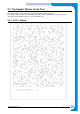
R E F E R E N C E I N F O R M AT I O N 2.3 The Sample Pattern for the Test The sample pattern shown in below is the standard pattern used in a factory. The contents of the life span and the printing speed are measured with the pattern shown in below. (The picture in the manual is 70% size of the actual A4 size.) 2.3.
R E F E R E N C E I N F O R M AT I O N 2.3.
R E F E R E N C E I N F O R M AT I O N 2.3.
R E F E R E N C E I N F O R M AT I O N 2-6 Service Manual Samsung Electronics
Specifications 3 3. Specifications Specfications are correct at the time of printing. Product specifications are subject to change without notice. See below for product specifications. 3.
Specifications 3.3 Scan Specification Items Halftone(Gray Scale) Scan Method Scan Speed ADF (seconds/scan) (SCX-4216F/4116) Descriptions 256 level Color CCD 25 sec 72 sec Resolution Halftone Scan Width Scan-to 3-2 Platen Optical Enhanced Width Length(Adf) Length(Platen) Remarks ITU-T #1 Chart Text/Mixed Mode : B/W Letter & 300dpi. (USB) Photo Mode : Gray Letter & 300dpi. (USB) 23 sec 600 x 600 dpi USB 4800 x 4800 dpi Parallel 2400 x 2400 dpi 256 level Max.216mm (8.5") Max. 356mm (14.0") Max.
Specifications 3.4 Copy Specification Items Copy Quality Selection or Original Image type selection Mode FCOT Descriptions Text Auto Photo Other Platen ADF Copy Speed / Letter Text Mixed Photo Resolution Scan Print Zoom Range Multi Copy Preset Contrast Control Copy Mode Collation Copy Auto return to default mode N-up copy AutoFit Copy Clone Poster 600x300dpi 600x300dpi 600x600dpi for Platen / 600x300dpi for ADF Power Save Approx. 54 seconds Stand by Approx. 12 seconds Power Save Approx.
Specifications 3.
Specifications 3.6 Fax Specification (SCX-4216F Only) Items Compatibility Communication System Modem Speed TX Speed Compression ECM Resolution Std Fine S.Fine Scan Speed(ADF) Std Fine S.
Specifications 3.
Specifications 3.
Specifications 3-8 Service Manual Samsung Electronics
SUMMARY OF PRODUCT 4 4. Summary of Product This chapter describes the functions and operating principal of the main component. 4.1 Printer Components 4.1.
SUMMARY OF PRODUCT 4.1.
SUMMARY OF PRODUCT 4.1.3 Control Panel < SCX-4216F > 1 2 3 4 5 6 Adjusts the brightness of the documents for the current copy job. Selects the document type for the current copy job. 1 C O P Y Allows you to use special copy features, such as Clone, Collation, Auto fit, 2-side, N-up (multiple pages on a sheet) and Poster copying. Makes a copy smaller or larger than the original. Selects the number of copies. Displays the current status and prompts during an operation.
SUMMARY OF PRODUCT Dials a number or enters alphanumeric characters. 4 Adjusts the resolution of the documents for the current fax job. Allows you to send a fax to multiple destinations. 5 F A X • Allows you to store frequently-dialed fax numbers using a one or two-digit speed dial or group number for automatic dialing and edit the stored numbers. • Allows you to print a Phonebook list.Redials the last number in Standby Mode or inserts a pause into a fax number in edit mode. Engages the telephone line.
SUMMARY OF PRODUCT < SCX-4016/4116 > 1 2 3 4 5 Adjusts the brightness of the documents for the current copy job. 1 Selects the document type for the current copy job. Displays the current status and prompts during an operation. 2 Turns on when the toner cartridge is empty. Scrolls through the options available for the selected menu item. Confirms the selection on the display. Enters Menu Mode and scrolls through the menus available. 3 Sends you back to the upper menu level.
SUMMARY OF PRODUCT 4.2 System Layout 4.2.1 Feeding section There is the universal cassette, which automatically loads paper and the manual feeder, which supplies paper one by one. The cassette has the friction pad which separates paper one by one, and it has a sensor, which functions to check the existence of loaded paper.
SUMMARY OF PRODUCT • Protecting device when overheating - 1st protecting device: H/W cuts off when detecting an overheating - 2nd protecting device: S/W cuts off when detecting an overheating - 3rd protecting device: Thermostat cuts off the power • Safety device - The power of the fuser is cut off when the front cover is open.
SUMMARY OF PRODUCT 4.2.6 LSU (Laser Scanner Unit) The LSU unit is controlled by the video controller. It scans the video data received from video controller with laser beam by using the rotation principal of the polygon mirror to create the latent image on the OPC drum. It is the core part of LBP. The OPC drum rotates as the same speed as the paper feeding speed.
SUMMARY OF PRODUCT 4.2.7 Toner Cartridge By using the electronic photo process, it creates a visual image. In the toner cartridge, the OPC unit and the developer unit are in a body. The OPC unit contains the OPC drum and charging roller.
SUMMARY OF PRODUCT 4.3 Main PBA(SPL Model) The Engine Board and the Controller Board are united on one board, and it is consists of a CPU part and print part in a functional aspect. The CPU functions as the bus controller, I/O handling, drivers, and PC inter-face. The main board sends the Current Image dlml Video data to the LSU and manages the Electrophotography for printing.
SUMMARY OF PRODUCT 4.3.1 ASIC (Chorus2) Samsung’s S3C46Q0X 16/32-bit RISC micro controller is designed to provide a cost-effective, low power, small die size and high performance micro-controller solution for MFP. The S3C46Q0X is developed using ARM7TDMI core, 0.18(m CMOS standard cell, and memory cell. •Main function block • 1.8V internal, 3.
SUMMARY OF PRODUCT 4.3.4 Sensor input circuit 1) Paper Empty Sensor The Paper empty sensor (Photo Interrupter) on the engine board informs the state of paper to CPU, whether it is empty or not with operation of the actuator. It detects a paper empty state by reading the D0 Bit of CPU, and then informs this fact by selecting the second LED(yellow) among the panel LEDs.
SUMMARY OF PRODUCT 4.4 SMPS & HVPS FEED SENSOR MANUAL SENSOR COVER OPEN SWITCH PAPER-EMPTY SENSOR F101 250V L2A EXIT SENSOR CN1 (H/L CON.) F1 110V : 125V/8A 220V : 250V T 5A H F2 110V : 125V/3A 220V : 250V 2A H CN3 (FAN CON.) MAIN PBA CON. MHV OPC THV DEV SUPPLY The SMPS supplies the DC power to the system. It takes 110V/220V and outputs the 5V, 12V and 24V to supply the power to the main board and ADF board.
SUMMARY OF PRODUCT 4.4.1 HVPS(High Voltage Power Supply) 1) Transfer High Voltage (THV+) - Function : Voltage to transfer developed toner on OPC drum to a paper. - Output voltage : +1300V DC±20V - Error : If THV (+) doesn't output, a ghost status (same character is printed after one cycle (76mm) of OPC) with a low density occurs due to a toner on OPC drum cannot normally transfer to a paper. 2) Charge Voltage (MHV) - Function : It is a voltage to charge entire surface of OPC with -900V ~ -1000V.
SUMMARY OF PRODUCT 4.4.2 SMPS(Switching Mode Power Supply) It is the power source for the whole system. It is an independent module, so it is possible to use for common use. It is mounted at the bottom of the set. It is consisted of the SMPS part, which supplies the DC power for driving the system, and the AC heater control part, which supplies the power to fuser. SMPS has four outputting channels (+5V, +12V, +12Vand +24Vs).
SUMMARY OF PRODUCT 6) Feature - Insulating resistance : over 50MΩ (at DC500V) Insulating revisiting pressure : Must be no problem within 1min. (at 1500Vzc, 10mA) Leaking voltage : under 3.
SUMMARY OF PRODUCT 4.5 Engine F/W 4.5.1 Feeding If feeding from a cassette, the drive of the pickup roller is controlled by controlling the solenoid. The on/off of the solenoid is controlled by controlling the general output port or the external output port. If feeding from a manual feeder, insert the paper according to the operation of the manual sensor, and by driving the main motor, insert the paper in front of the feed sensor. While paper moves, occurrence of jam is judged as below. (Refer to the [6.
SUMMARY OF PRODUCT 4.5.4 Fusing The temperature change of the heat roller’s surface is changed to the resistance value through the thermistor. By converting the voltage value, which impressed to the resistance, to the digital value through the AD converter, the temperature is decided. The AC power is controlled by comparing the target temperature to the value from the thermistor.
SUMMARY OF PRODUCT 4.6 LIU PBA LIU board is a Line interface unit, and it is a circuit for interfacing a telephone line with a modem. The circuit is consisted of matching transfer to conform to impedance of a receiving telephone line and a circuit to conform to impedance of a modem. Also, there are a ring detect circuit to detect a ring signal from a switchboard and a surge absorber to protect it from a thunderbolt located on a line input unit.
Disassembly and Reassembly 5 5. Disassembly and Reassembly 5.1 General Precautions on Disassembly When you disassemble and reassemble components, you must use extreme caution. The close proximity of cables to moving parts makes proper routing a must. If components are removed, any cables disturbed by the procedure must be restored as close as possible to their original positions. Before removing any component from the machine, note the cable routing that will be affected.
Disassembly and Reassembly 5.2 Rear Cover 1. Remove the four screws securing the Rear Cover. 3. Unlatch the (Cover Face Up) securing the Rear cover, as shown below.Then lift the (Cover Face Up) out. Cover Face Up 2. Remove the Rear Cover from the Frame Ass'y and Scanner Ass'y.
Disassembly and Reassembly 5.3 Side Cover (LH, RH) 1. Before you remove the Side Cover (LH, RH), you should remove: - Rear Cover (see page 5-2) 3. Lift the LH and RH Side Cover out in the direction of arrow. Side Cover(LH) 2. Unplug the Speaker Harness, as shown below.
Disassembly and Reassembly 5.4 Front Cover 1. Take out the Cassette. 3. Unlatch the Front Cover securing the Frame Ass'y. Then remove the Front Cover, as shown below. Cassette Front Cover 2. OPen the Front Cover.
Disassembly and Reassembly 5.5 Scanner Ass'y 1. Before you remove the Scanner Ass'y, you should remove: - Rear Cover (see page 5-2) - Side Cover (LH, RH) (see page 5-3) 4. Pull up the Scanner Ass'y, as shown below. Scanner Ass’y 2. Remove the two screws securing the Scanner Ass'y, as shown below. 3. Unplug the 6 connectors from the Connector PBA , as shown below. 5. Pull the Platen Cover upward and remove it.
Disassembly and Reassembly 6. Remove the three screws securing the Scan Ass’y. 7. Lift the OPE Unit out. Then unplug the two connectors from the OPE Unit and remove it. 8. Remove the four screws securing the Scan Upper. 9. Unlatch the Scan Upper securing the Scan Ass’y Then pull the Scan Upper upward and remove it.
Disassembly and Reassembly 10. Remove the CCD Cable, as shown below. 12. Pull up the CCD Shaft and take out the Scanner Module. Scanner Module CCD Cable CCD Shaft Belt Holder 11. Push the Belt Holder and take out the Belt, as shown below. Belt 13. Remove the Reduction Gear and Idle Gear, as shown below.
Disassembly and Reassembly 14. Remove the two screws and take out the Motor Bracket. 16. Unlatch the Open Sensor and remove it, as shown below. Motor Bracket Open Sensor 15. Unplug the one connector from the Open Sensor Ass'y.
Disassembly and Reassembly 5.6 ADF Motor Ass'y 1. Before you remove the ADF Motor Ass'y, you should remove: - Rear Cover (see page 5-2) - Side Cover (LH, RH) (see page 5-3) - Scanner Ass’y (see page 5-5) 2. Remove the two screws securing the ADF Ass'y and remove it. 5. Remove the two screws securing the Upper Cover and remove it, as shown below. Upper Cover ADF Ass’y 3. Remove the Open Cover, as shown below. Open Cover 6. Unplug the one connector and remove six screws securing the ADF Motor Ass'y.
Disassembly and Reassembly 5.7 OPE Unit 1. Before you remove the OPE Unit, you should remove: - Rear Cover (see page 5-2) - Side Cover (LH, RH) (see page 5-3) - Scanner Ass’y (see page 5-5) 4. Remove the Key Pad from the OPE Cover. 2. Remove the six screws securing the OPE PBA from the OPE Cover. OPE Cover OPE PBA Key Pad 3. Remove the Contact Rubber from the OPE Cover.
Disassembly and Reassembly 5.8 Middle Cover & Exit Roller 1. Before you remove the Exit Roller, you should remove: - Rear Cover (see page 5-2) - Front Cover Ass’y (see page 5-4) - Side Cover (LH, RH) (see page 5-3) - Scanner Ass’y (see page 5-5) 4. Remove the two screws securing the Rear-Upper Cover, as shown below 2. Remove the six screws securing the Top Cover and remove it. .5. Remove the Exit Gear and Bearing, as shown below. Exit Gear Bearing 3.
Disassembly and Reassembly 5.9 Engine Shield Ass’y 1. Before you remove the Engine Shield Ass'y, you should remove: - Rear Cover (see page 5-2) - Side Cover(LH, RH) (see page 5-3) - Scanner (see page 5-5) 2. Remove the ten screws securing the Engine Shield Ass'y and remove it. Then unplug the all the connectors from the Main PBA and SMPS. 2. Remove the two screws securing and unplug the FPC cable From the Main PBA. Then reomve the LIU PBA LIU PBA Engine Shield Ass’y 2. Unplug two connector.
Disassembly and Reassembly 5.10 Main PBA 1. Before you remove the Main PBA, you should remove: - Rear Cover (see page 5-2) - Side Cover(LH, RH) (see page 5-3) - Scanner (see page 5-5) - Engine Shield Ass’y(see page 5-10) Main PBA 2. Unplug the one connector and remove the five screws securing the Main PBA. Then lift the Main PBA out, as shown below.
Disassembly and Reassembly 5.11 SMPS 1. Before you remove the SMPS, you should remove: - Rear Cover (see page 5-2) - Side Cover(LH, RH) (see page 5-3) - Scanner Ass’y (see page 5-5) - Engine Shield Ass’y(see page 5-12) 4. Remove the three screws securing the SMPS. Then lift the SMPS out, as shown below. SMPS 2. Remove the three screws securing the Inlet Bracket and remove it Inlet Bracket 2. Unplug the one connector and remove the one screw securing the Engine Shield.
Disassembly and Reassembly 5.12 Fuser Ass'y 1. Before you remove the Fuser Ass'y, you should remove: - Rear Cover (see page 5-2) - Side Cover(LH, RH) (see page 5-3) - Scanner Ass’y (see page 5-5) - Engine Shield Ass’y(see page 5-12) 4. Remove the two screws securing the Halogen Lamp. Then take out the Halogen Lamp from the Heat Roller Heat Roller 2. Unplug the two connectors from the Main PBA and SMPS, as shown below. Then remove the four screws securing the Fuser Ass'y and remove it.
Disassembly and Reassembly 7. Unwrap the Thermister Harness, as shown below. 8. Remove the one screw securing the Thermister and remove it, as shown below.
Disassembly and Reassembly 5.13 Fan 1. Before you remove the Fan, you should remove: - Rear Cover (see page 5-2) - Side Cover (RH) (see page 5-3) 2. Unplug the connector from the SMPS and remove the one screw. Then take out the Fan.
Disassembly and Reassembly 5.14 LSU 1. Before you remove the LSU, you should remove: - Rear Cover (see page 5-2) - Side Cover (LH, RH) (see page 5-3) - Scanner Ass’y (see page 5-5) - Front Cover (see page 5-4) - Middle Cover (see page 5-11) 3. Remove the four screws securing the LSU and remove it. LSU 2. Unplug the two connectors. 5.15 Drive Ass'y 1. Before you remove the Drive Ass'y, you should remove: - Rear Cover (see page 5-2) - Side Cover (LH) (see page 5-3) 3.
Disassembly and Reassembly 5.16 Transfer Ass'y 1. Before you remove the Transfer Ass'y, you should remove: - Rear Cover (see page 5-2) - Side Cover (LH, RH) (see page 5-3) - Scanner Ass’y (see page 5-5) - Front Cover (see page 5-4) - Middle Cover (see page 5-11) - LSU (see page 5-18) 3. Unplug the PTL Holder connector, then remove the PTL Holder and PTL Lens, as shown below. PTL Holder PTL Lens 2. Remove the three screws securing the Transfer Earth and remove it. Transfer Earth 4.
Disassembly and Reassembly 5.17 Feed Ass'y 1. Before you remove the Feed Ass'y, you should remove: - Rear Cover (see page 5-2) - Side Cover (LH, RH) (see page 5-3) - Scanner Ass’y (see page 5-5) - Front Cover (see page 5-4) - Middle Cover (see page 5-11) - Drive Ass’y (see page 5-18) 4. Remove the three screws securing the Feed Bracket and remove it. Feed Bracket 2. Remove the two screws securing the Guide Paper and remove it. Guide paper 5. Remove the Idle Gear and Feed Gear2. Feed Gear2 3.
Disassembly and Reassembly 6. Remove the Feed Gear1 Ass'y. 7. Pull up the Feed Roller and Feed Roller1.
Disassembly and Reassembly 5.18 Pick-Up Ass'y & Solenoid 1. Before you remove the Pick-Up Ass'y, you should remove: - Rear Cover (see page 5-2) - Side Cover (LH, RH) (see page 5-3) - Front Cover (see page 5-4) - Scanner Ass’y (see page 5-5) - Middle Cover (see page 5-11) - Engine Shield Ass,y (see page 5-12) - Drive Ass’y (see page 5-18) 4. Take out the Pick-Up Ass'y, as shown below. 2. Remove the three screws securing the Feed Bracket and remove it. Feed Bracket Bush 1 2 5.
ALIGNMENT & ADJUSTMENTS 6 6. Alignment and Adjustments This chapter describes the main functions for service, such as the product maintenance method, the test output related to maintenance and repair, DCU using method, Jam removing method, and so on. It includes the contents of manual. 6.
ALIGNMENT & ADJUSTMENTS 6.1.1 Copy & Scan Document Path Scanner Part 3 2 1 2 3 4 5 6 7 8 1 4 5 6 7 White-Sheet 8 CCD-Module Doc. Paper (30 Sheets) Pickup Roller ADF Roller Sensor - Doc. Sensor - Regi Sensor - Scan Feed Roller Exit Roller 6.1.2 Printer Paper Path 1) After receiving print job, the printer feeds the printing paper from the cassette or manual feeder. 2) The fed paper passes the paper feeding sensor.
ALIGNMENT & ADJUSTMENTS 6.2 Clearing Paper Jams Occasionally, paper can be jammed during a print job. Some of the causes include: • The tray is loaded improperly or overfilled. • The tray has been pulled out during a print job. • The front cover has been opened during a print job. • Paper was used that does not meet paper specifications. • Paper that is outside of the supported size range was used. If a paper jam occurs, the On Line/Error LED on the control panel lights red.
ALIGNMENT & ADJUSTMENTS 6.2.1 Clearing Document Jams(For SCX-4216F/SCX-4116 only) If a document jams while it is feeding through the ADF (Automatic Document Feeder),“DOCUMENT JAM ” appears on the display. 6.2.1.1 Input Misfeed 1) Open the ADF top cover. 3) Close the ADF top cover.Then load the documents back into the ADF. NOTE : To prevent document jams,use the document glass for the thick,thin or mixed documents. 2) Pull the document gently to the right and out of the ADF.
ALIGNMENT & ADJUSTMENTS 6.2.1.2 Exit Misfeed 1) Open the document cover and turn the release knob to remove the misfed documents from the exit area. 2) Close the document cover.Then load the documents back into the ADF. 6.2.1.3 RollerMisfeed 1) Open the document cover. 2) Turn the release knob so that you can easily remove the misfed document,and remove the document from the ADF or the feed area by carefully pulling it towards the right by using both hands. 3) Close the document cover.
ALIGNMENT & ADJUSTMENTS 6.2.2 Clearing Paper Jams If paper jams occur,“PAPER JAM ” appears on the display..Refer to the table below to locate and clear the paper jam. PAPER JAM 0 PAPER JAM 2 PAPER JAM 1 BYPASS JAM : In the paper feed area : In the paper exit area : In the fuser area or around the toner cartridge : In the Bypass tray Follow the steps below to clear a jam.To avoid tearing the paper, pull the jammed paper out gently and slowly. 6.2.2.
ALIGNMENT & ADJUSTMENTS 6.2.2.2 JAM 2 (In the Paper Exit Area) 1) Open and close the front cover.The jammed paper automatically exits the machine. If the paper does not exit,continue to Step 2. 4) Remove the jammed paper by gently pulling it straight out.. 2) Gently pull the paper out of the front output tray. 5) Close the rear cover. 3) If there is any resistance when you pull the paper or the paper is not seen in the front output tray,open the rear cover.
ALIGNMENT & ADJUSTMENTS 6.2.2.3 JAM1 (In the Fuser Area of Around the Toner Cartridge Area) NOTE : The fuser area is hot.Be careful when removing paper from the machine. 1) Open the front cover and remove the toner cartridge. 3) Replace the toner cartridge and close the front cover. Printing automatically resumes. 2) Remove the jammed paper by gently pulling it straight out.
ALIGNMENT & ADJUSTMENTS 6.2.2.4 BYPASS JAM (In the Bypass Tray) “BYPASS JAM ” appears on the display when the machine does not detect paper in the Bypass tray due to no paper or improper paper loading when you try to print using the Bypass tray. “BYPASS JAM ” also may occur when the paper is not properly fed into the machine through the Bypass tray.In that case,pull the paper out of the machine. 6.2.2.5 Tips for Avoiding Paper Jams By selecting the correct paper types,most paper jams can be avoided.
ALIGNMENT & ADJUSTMENTS 6.3 User Mode(SCX-4116 & SCX-4016) The table in the bellow explains the possible setting functions by user. The details about the ways to use are explained in the user manual. In the service manual, the items are about the possible set-up by user. 1.Paper Setting Paper Tray Paper Size 2.Copy Setup Change Default Timeout System Data 9.Maintenance 8.Machine Setup Clean Drum Clear Memory 6-10 6.
ALIGNMENT & ADJUSTMENTS 6.4 User Mode(SCX-4216F) The table in the bellow explains the possible setting functions by user. The details about the ways to use are explained in the user manual. In the service manual, the items are about the possible set-up by user. 1.Paper Setting Paper Tray Paper Size 4.Fax Feature Delay Fax Priority Fax Add / Cancel 7.Sound/Volume Speaker Ringer Key Sound Alarm sound 2.Copy Setup Change Default Timeout 5.Advanced Fax 3.
ALIGNMENT & ADJUSTMENTS 6.5 Tech Mode 6.5.1 How to Enter Tech Mode In service (tech) mode, the technician can check the machine and perform various test to isolate the cause of a malfunction. While in Tech mode, the machine still performs all normal operations. 1)To enter the Tech mode (SCX-4216F) To enter the Tech mode, press in sequence, and the LCD briefly displays ‘TECH’, the machine has entered service (tech) mode.
ALIGNMENT & ADJUSTMENTS 6.5.3 Data Setup SEND LEVEL You can set the level of the transmission signal. Typically, the Tx level should be under -12 dBm. Caution: The Send Fax Level is set at the best condition in the shipment from factory. Never change settings arbitrarily. MODEM SPEED You can set the maximum modem speed.
ALIGNMENT & ADJUSTMENTS 6.5.4 Machine Test SWITCH TEST Use this feature to test all keys on the operation control panel. The result is displayed on the LCD window each time you press a key. MODEM TEST Use this feature to hear various transmission signals to the telephone line from the modem and to check the modem. If no transmission signal sound is heard, it means the modem part of the main board malfunctioned. DRAM TEST Use this feature to test the machine's DRAM. The result appears in the LCD display.
ALIGNMENT & ADJUSTMENTS 6.5.5 Report PROTOCOL LIST This list shows the sequence of the CCITT group 3 T.30 protocol during the most recent sending or receiving operation. Use this list to check for send and receive errors. If a communication error occurs while the machine is in TECH mode, the protocol list will print automatically. SYSTEM DATA This list provides a list of the user system data settings and tech mode settings.
ALIGNMENT & ADJUSTMENTS 6.6 Engine Test Mode The Engine Tests Mode supplies useful functions to check conducting condition of engine. It tests the conducting condition of each device and displays the result of the test at the LCD. It is classified in 5. items (0~4), and the functions of items are as bellows. 6.6.1 To enter the Engine Test Mode 1)To enter the Engine Test mode (SCX-4216F) Press in sequence, and the LCD briefly displays ‘Engine Test’, the machine has entered Engine Test Mode.
ALIGNMENT & ADJUSTMENTS 6.7 Identify Sale Date(Only SCX-4216F) This function confirms the date that consumer bought product and used the product for the first time. When the consumer first operate the machine, it will start a scan and page count. The time the machine was first used is remembered. These settings are are remembered after memory delete (Clear All Memory). < Method > Press MENU, #, 1, 9, 3, # in sequence.Firmware version is displayed on LCD.
ALIGNMENT & ADJUSTMENTS 6.8 Consumables and Replacement Parts The cycle period outlined below is a general guideline for maintenance. The example list is for an average usage of 50 transmitted and received documents per day. Environmental conditions and actual use will may vary. The cycle period given below is for reference only.
ALIGNMENT & ADJUSTMENTS 6.9 Abnormal Image Printing and Defective Roller If abnormal image prints periodically, check the parts shown below. LSU Fuser Toner Cartridge CR OPC PR SR PTL MP Sensor FR R TR DR K/ PIC 1 2 3 4 5 6 7 OPC Drum Charge Roller Supply Roller Transfer Roller Heat Roller Pressure Roller Developing Roller No Roller Abnormal image period Kind of abnormal image 1 OPC Drum 75.5mm White spot, Block spot 2 Charge Roller 37.7mm Black spot 3 Supply Roller 37.
ALIGNMENT & ADJUSTMENTS 6-20 Service Manual Samsung Electronics
TROUBLESHOOTING 7 7. Troubleshooting 7.1 Paper Feeding Problems 7.1.1 Wrong Print Position • Description Printing begins when the paper is in the wrong position. Check and Cause Solution A defective feed sensor actuator can cause incorrect timing. Replace the defective actuator 7.1.2 JAM 0 1. Paper has not exited from the cassette. 2. Jam-0 occurs if the paper feeds into the printer. • Description Check and Cause LSU Fuser EXIT Sensor Toner Cartridge CR OPC PR SR PTL FR Feed Sensor 1.
TROUBLESHOOTING 7.1.3 JAM 1 1. Recording paper is jammed in front of or inside the fuser. 2. Recording paper is stuck in the discharge roller and in the fuser just after passing through the Actuator-Feed. • Description Check and Cause Solution LSU Fuser EXIT Sensor Toner Cartridge CR OPC PR SR PTL FR Feed Sensor MP Sensor 1. If the recording paper is jammed in front of or inside the fuser. 1. Replace the SMPS. 2.
TROUBLESHOOTING 7.1.5 Multi-Feeding • Description Multiple sheets of paper are fed at once. Check and Cause Solution 1. Solenoid malfunction(the solenoid does not work properly): Perform Engine Test Mode : Diagnostic Mode code 0. 1. Replace the solenoid if necessary. 2. Friction-Pad is contaminated with foreign matter.(oil..) 2. Clean the friction-pad with soft cloth dampened with IPA(Isopropyl Alcohol). 3. The face of paper is blended. 3. Use the smooth paper. 7.1.
TROUBLESHOOTING 7.1.7 Paper rolled in the OPC • Description Paper is rolled up in the OPC. Check and Cause Solution 1. Paper is too thin. 1. Recommend to use normal paper thickness. 2. The face of paper is curled. 2. How to remove the rolled paper in the OPC. • Remove the paper while turning the OPC against the ongoing direction. • Clean fingerprints on the OPC softly with soft cloth dampened with IPA(Isopropyl Alcohol) or tissue. 7.1.
TROUBLESHOOTING 7.2. Printing Problems (malfunction) 7.2.1 Defective Operation (LCD WINDOW • Description ) Display Strange characters are displayed on the OPE Panel and buttons are not operated. Check and Cause Solution 1. Clear the memory.(see page 6.5.3) 1. Try again after clearing the memory. 2. Check if OPE HARNESS is connected to the Connection B'd correctly. 2.
TROUBLESHOOTING 7.2.3 Not functioning of the fuser gear due to melting away • Description The Motor breaks away from its place due to gear melting away. Check and Cause 1. Check the Heat Lamp. Solution 1. Replace the Fuser. 2. Replace the Main PBA. 3. Replace the SMPS. 7.2.4 Paper Empty • Description The paper lamp on the operator panel is on even when paper is loaded in the cassette. Check and Cause Solution 1. Bending or deformation of the actuator of the paper sensor. 1.
TROUBLESHOOTING 7.2.6 Door Open • Description The ERROR lamp is on even when the print Door is closed. Check and Cause Solution 1. The hook lever in the Front Cover may be defective. 1. Replace the hook lever, if defective. 2. Check the Connector(CN1) and Circuit of the Cover Switch department in the Main PBA. 2. Check the insertion of the Door Open S/W Connect. 3. Replace the Main PBA or Door Open S/W. 7.2.
TROUBLESHOOTING 7.2.8 Defective Motor operation • Description Main Motor is not driving when printing, and paper does not feed into the printer, resulting 'Jam 0'. Check and Cause Solution 1. Motor harness or sub PCB may be defective. 1. Check the Motor harness, replace it, if defective. 2. Perform Engine Test Mode diagnostic code 0 and Check the Motor operation. 2. Replace the SMPS, if necessary. 7.2.
TROUBLESHOOTING 7.2.10 Vertical Line Getting Curved • Description When printing, vertical line gets curved. Check and Cause 1. If the supply of +24v is unstable in the Main Control board linking with LSU, check drive by Engine Test Mode : Diagnostic Code 1 LSU Motor on. Solution 1. Replace LSU. 2. Replace the Main Control board.
TROUBLESHOOTING 7.3 Printing Quality Problems 7.3.1 Vertical Black Line and Band • Description Digital Printer Digital Printer Digital Printer Digital Printer Digital Printer 1. Straight thin black vertical line occurs in the printing. 2. Dark black vertical band occur in the printing. Check and Cause Solution 1. Damaged develop roller in the Developer. Deformed Doctor-blade or cleaningblade. 1. If causes 1 and 2 occur in the developer cartridge, replace the developer and try to print out. 2.
TROUBLESHOOTING 7.3.3 Horizontal Black Band • Description 1. Dark or blurry horizontal stripes occur in the printing periodically. (They may not occur periodically.) Check and Cause Digital Printer Digital Printer Digital Printer Digital Printer Digital Printer Solution 1. Bad contacts of the voltage terminals to developer. 1. Clean each voltage terminal of the Charge, Supply, Develop and Transfer roller. (remove the toner particles and paper particles) 2. The rollers of developer may be stained.
TROUBLESHOOTING 7.3.5 Light Image • Description The printed image is light, with no ghost. Check and Cause Digital Printer Digital Printer Digital Printer Digital Printer Digital Printer Solution 1. Develop roller is stained when the toner of developer cartridge is almost consumed. 1. Check if the Toner Save Mode is off. 2. Ambient temperature is below than 10°C. 2. No 1 : Replace the developer cartridge and try to print out. 3.
TROUBLESHOOTING 7.3.7 Uneven Density • Description Print density is uneven between left and right. Check and Cause Solution 1. The pressure force on the left and right springs of the transfer roller is not even, the springs are damaged, the transfer roller is improperly installed, or the transfer roller bushing or holder is damaged. 1. Replace both the left and right Spring Holder. 2. The life of the Developer has expired. 2.
TROUBLESHOOTING 7.3.9 Ghost (1) • Description Check and Cause 75.5 mm Digital Printer Digital Printer Digital Printer Digital Printer Digital Printer Digital Printer Ghost occurs at 75.5 mm intervals of the OPC drum in the whole printing. Solution 1. Bad contacts caused by contamination from toner particles between high voltage terminal in the main body and the electrode of the Developer. 1. Clean the contaminated terminals. 2.
TROUBLESHOOTING 7.3.11 Ghost (3) • Description Check and Cause Solution 1. The life of the developer may be expired. 1. Problem in the toner cartridge, replace the toner cartridge and try to print out. 2. The abnormal voltage and bad contact of the terminal of the supply roller 2. Check the approved voltage of the supply roller and contact of the terminal and adjust if necessary.
TROUBLESHOOTING 7.3.14 Stains on back of the page • Description Digital Digital Pri Digital Printer Digital Printer Digital Printer The back of the page is stained at 56.1 mm intervals. Check and Cause Solution 1. Transfer roller is contaminated. 1. Perform the OPC Cleaning Mode Print 2 or 3 times. Run Self-Test to remove the contamination of the transfer roller. 2. Pressure roller is contaminated. 2. Replace the transfer roller if contaminated severely. 3.
TROUBLESHOOTING 7.4 Fax & Phone Problems 7.4.1 No Dial Tone • Description While on-hook button is pressed, there is no dial tone. Check and Cause Solution 1. Check if the telephone line cord is connected to TEL LINE correctly. 1. If the telephone cord is normal but there is no dial tone, then try to replace the LIU B'd. 2. Check if it makes CLICK sound while OHD key is pressed. 2. If you cannot hear the OHD CLICK sound, the OPE Ass’y may be defective. Try to replace the OPE Ass’y. 3.
TROUBLESHOOTING 7.4.3 Defective FAX FORWARD/RECEIVE • Description The FAX FORWARD/RECEIVE is not functioning. Check and Cause 1. Check if you can catch a dial tone by pressing OHD. 2. Check if you can catch a RECEIVE tone while MODEM testing in the TECH Mode. Solution 1. If the MODEM testing is normal and there is no dial tone, then try to replace the LIU B'd. 2. If the MODEM testing is abnormal, try to replace the Main B'd. 7.4.
TROUBLESHOOTING 7.4.5 Defective FAX RECEIVE (1) • Description FORWARD is functioning, but RECEIVE is not functioning or the received data are broken. Check and Cause 1.Check if there is NOISE when pressing on-hook dial. Solution 1.If it makes NOISE while on-hooking, replace or repair the telephone line. 2.Check the RECEIVE condition by trying to receive a FAX at another fax machine. 7.4.6 Defective FAX RECEIVE (2) • Description The received data are lengthened or cut in the printing.
TROUBLESHOOTING 7.4.8 Defective FAX RECEIVE (4) • Description The received data is reduced by more than 50% in the printing. Check and Cause Check the FAX status of the forwarding side. Solution After checking the data of the forwarding side, correct the FAX of the forwarding side. 7.4.9 Defective Automatic Receiving • Description The automatic receiving function is not working. Check and Cause Solution 1. Check if the RECEIVE Mode is TEL MODE or FAX MODE. 1.
TROUBLESHOOTING 7.5 Copy Problems 7.5.1 White Copy • Description Blank page is printed out when copy. Check and Cause Solution 1. Check the Scan-Cover open. 1. Room light ca transit a thin original. 2. Check shading profile. 2. Remake shading profile in the tech mode. 3. Check white/black reference voltage in Main PBA. 3. Replace U60 if it is defective. • U60-154 = 0.5V • U60-155 = 3.3V 7.5.2 Black Copy • Description Black page is printed out when Copy. Check and Cause Solution 1.
TROUBLESHOOTING 7.5.3 Abnormal noise • Description There is noise when copy. Check and Cause Solution 1. Check the Scanner Motor and any mechanical disturbance. 1. Check the right position of the Scanner Motor, and check the any mechanical disturbance in the CCD carriage part. 2. Check the Motor Driver in Driver PBA. 2. If any driver is defective, replace it. • Connection PBA U4-1, 19 or U5-1, 19=0V to 24V swing signal when operating. 7.5.
TROUBLESHOOTING 7.6 Scanning Problems 7.6.1 Defective PC Scan • Description The PC Scan is not functioning at all. Check and Cause Solution 1. Check the Cable (USB or Parallel) 1. If the PC and the cable are not connected properly, reconnect it. 2. Check if the driver is installed properly. 2. After confirming that it is proper by performing a PC printing test related to driver setup, if it is not so, reinstall it. (Refer to User's Manual.) 3. Check if copy function operates normally. 3.
TROUBLESHOOTING 7.7 Toner Cartridge Service It is not guaranteed for the default caused by using other toner cartridge other than the cartridge supplied by the Samsung Electronic or caused by non-licensed refill production. 7.7.1 Precautions on Safe-keeping of Toner Cartridge Excessive exposure to direct light more than a few minutes may cause damage to the cartridge. 7.7.
TROUBLESHOOTING 7.7.4 Signs and Measures at Poor toner cartridge Fault Light image and partially blank image (The life is ended.) Signs Cause & Check • The printed image is light or unclean and untidy. 1. If the image is light or unclean and untidy printed image Shake the developer and then recheck. • Some part of the (1)NG: Check the weight of the image is not printdeveloper ed. (2)OK: Lack of toner, so the life is nearly closed. • Periodically a noise 2.
TROUBLESHOOTING Fault White Black spot Signs Cause & Check 1. If light or dark periodical black dots occur, this is because the developer rollers are contaminated with foreign substance or paper particles. • White spots occur in the image period- (1) 37.7 mm interval : Charged roller ically. (2) 75.5 mm interval : OPC cycle • Light or dark black dots on the image occur periodically. 2.
TROUBLESHOOTING Fault Ghost & Image Contamination Signs Cause & Check Solution • The printed image is too light or dark, or partially contaminated black. 1. The printed image is too light or dark, or partially contaminated black. (1)Check whether foreign substance or toner are stuck to the terminal(point of contact) of the developer. (2)Check whether the terminal assembly is normal. 1. All of 1, 2, 3 above (1)Remove toner and foreign substances adhered to the contact point of the developer.
EXPLODED VIEW & PARTS LIST 8 8. Exploded Views and Parts List 8.1 Main Assembly Exploded view ............................................................................... page(5-2) 8.2 Rx Drive Ass’y Exploded view ................................................................................ page(5-5) 8.3 ADF Assembly Exploded view ................................................................................ page(5-6) 8.4 OPE Assembly Exploded view(SCX-4216F) ......................................
8-2 1-3 1-1 1-2 0 1-4 20 10-4 1 10-5 10-3 10-6 12 10-1 10-2 26 9 10 22 12-3 12-2 12-1 3 28 8 11 4 25 16 5 25-2 21 23 14 27 19 2 18 17-1 14-1 25-1 25-2 15 24 7 17-2 17-3 13 17 14-2 EXPLODED VIEW & PARTS LIST 8.
EXPLODED VIEW & PARTS LIST Main Assembly Parts List SA : Service Available O : Service available X : Service not available No. Description SEC.
EXPLODED VIEW & PARTS LIST Main Assembly Parts List(cont.) SA : Service Available O : Service available X : Service not available No. 17-3 8-4 Description SEC.
EXPLODED VIEW & PARTS LIST 8.2 RX Drive Assembly 0 7 6 8 1 9 10 2 4 5 3 4 5 RX Drive Assembly Parts List SA : Service Available O : Service available X : Service not available No. Description SEC.
EXPLODED VIEW & PARTS LIST 8.
EXPLODED VIEW & PARTS LIST 4 4-3-2 4-3-5 4-3-4 4-3-3 4-3-1 4-3 4-8 4-9 4-4 4-7 S 4-7 S 4-1 4-4 4-5 4-6 4-2 Service Manual Samsung Electronics 8-7
EXPLODED VIEW & PARTS LIST ADF Assembly Parts List SA : Service Available O : Service available X : Service not available No. SEC.
EXPLODED VIEW & PARTS LIST ADF Assembly Parts List(cont.) SA : Service Available O : Service available X : Service not available No. Description SEC.
EXPLODED VIEW & PARTS LIST 8.
EXPLODED VIEW & PARTS LIST OPE Unit Assembly Parts List(SCX-4216F) SA : Service Available O : Service available X : Service not available No. Description SEC.
EXPLODED VIEW & PARTS LIST 8.
EXPLODED VIEW & PARTS LIST OPE Unit Assembly Parts List(SCX-4116/4016) SA : Service Available O : Service available X : Service not available No. SEC.
EXPLODED VIEW & PARTS LIST 8.
EXPLODED VIEW & PARTS LIST Scanner Assembly Parts List SA : Service Available O : Service available X : Service not available No. Description SEC.
EXPLODED VIEW & PARTS LIST 8.7 Middle Cover Assembly 7 17 6 16 8 15 9 5 4 7 10 14 13 0 3 12 11 1 2 Middle Cover Assembly Parts List SA : Service Available O : Service available X : Service not available No. 8-16 Description SEC.
Samsung Electronics 47-2 50 47-1 46 26 47-4 51 47-3 47 47-5 45-1 45-2 43 27-1 45-3 45 44 42 27-2 25 6 0 27-3 27-5 27-4 54 41 16 40 39 55 27-7 24 35 33 21 27-6 27-4 20 19 37 38 27 23 5 25 52 6 6 17 7 53 22 18 5 36 13 15 37 38 29 56 14 1 10 32 31 3 11 49 16 28 8 30 9 34 Transfer Roller 12 4 2 48 EXPLODED VIEW & PARTS LIST 8.
EXPLODED VIEW & PARTS LIST Frame Assembly Parts List SA : Service Available O : Service available X : Service not available No. 8-18 Description SEC.
EXPLODED VIEW & PARTS LIST Frame Assembly Parts List(Cont.) SA : Service Available O : Service available X : Service not available No. Description SEC.
EXPLODED VIEW & PARTS LIST 8.
EXPLODED VIEW & PARTS LIST Fuser Assembly Parts List SA : Service Available O : Service available X : Service not available No. Description SEC.
EXPLODED VIEW & PARTS LIST 8.
EXPLODED VIEW & PARTS LIST Cassette Assembly Parts List SA : Service Available O : Service available X : Service not available No. Description SEC.
EXPLODED VIEW & PARTS LIST 8-24 Service Manual Samsung Electronics
Samsung Electronics CCD FLATEN MOTOR FLATEN COVER 4P 24P CCD LAMP CONTROL FLATEN MOTOR DRIVER (TEA3718X2) ADF MOTOR 16P ADF/ FLAT MOT CONTROL 6P SENSOR DRIVER KEY SCAN LCD/LED DRIVER HT48C50 CONN. 3P OPE 14P LCD (16X2) 4P ADF REGI SEN. ADF DET SEN. ADF POS SEN. SCX-4216F, 4116 only IMAGE PROCESSOR CACHE (4K) MEMORY I/F UARTX2 PVC DMAC I/O I/F 1 TU USB 1.1 P1284 GEU ARM9TDMI S3C46Q0X ADF MOTOR DRIVER (TEA3718X2) ADF A D F 24PX2 IEEE1284 USB 1.
Samsung Electronics CN1 1.DG ND 2.+5V 3.O PE_TX 4.O PE_RS T 5.O PE_TX 6.nLED8 1, 3, 5, 7, 24 : GND24 2. : VOUT_B 4. : VOUT_R 6. : VOUT_G 9, 10, 11. : TG 12, 20. : DGND 13. : RS 14. : CLK1 15. : CLK2 18. : CP 19. : +5V 21. : HOME 22. : +24V 23. : INV_POW CN2 OPE B’d CCD MODULE 1.+5V 2.Co ntrol 3.G ND5 FLATE N COV ER SE NS OR Ex trnal LI NE LIU B’d CN3 CN3 FEE D S ENS OR E X IT S ENS OR SMPS / HVPS B’d CN2 MICRO SWITCH +24VX CUT (LSU, SOL, MOTOR) CN 8 FLATEN MOTOR CN 7 CN 2 1.MA 2.MB 3.