
Installation Guide (Installation manual) (ver.1.0)


10
11
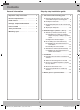
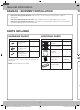
This microwave oven is compatible with the following
three types of ventilation:
NOTE: This microwave is shipped assembled
for Outside Top Exhaust (except for non-vented
models). An exhaust adaptor is shipped assembled
and attached to the filler-upper. Select the type of
ventilation required for your installation and proceed to
that section.
See page 12 See page 13
A Charcoal Filter Accessory Kit is required for the
nonvented exhaust. (See your Owner’s Manual for the
kit number.)
See page 14
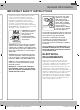
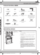
C
L
CAUTION: Wear gloves to avoid cutting
fingers on sharp edges.
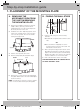
Area E
Hole B
Hole A
Centerline
notches
Draw a Vertical Line
on Wall from Center
of Top Cabinet
Draw a Horizontal line on wall from
bottom of “Rear Wall Template”.
Horizontal Line
Horizontal Line
the wall along the bottom
Area E
notches
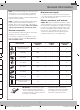
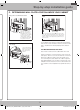
: Wear gloves to avoid cutting fingers
on sharp edges.
1. Draw a Horizontal line on the wall at the
bottom of the “Rear Wall Template”.
2. Drill ⅝˝ holes for toggle bolts in 3 locations
(Hole A, Hole B, Hole C) as shown in the
illustration above. If the location of a hole
lines up with a stud, drill a
3
/
16
˝ hole for a
wood screw. You cannot use a toggle bolt to
attach the wall plate to a stud.
3. Holes A, B and C are inside area E. If none
of these holes line up with a stud, find a stud
in area E that lines up with a hole circle in
Area E, and then drill a
3
/
16
˝ hole into it for
a wood screw. You must have at least one
wood screw mounted firmly into a stud to
support the weight of the microwave. Set
the mounting plate aside.
SMH1927_XAA_DE68-04108A-01_EN_120725.indd 10 2012-07-25 �� 7:54:33