NETWORK CAMERA User Manual SNB-5003/SNB-5004 SND-5083/SND-5084
Network Camera User Manual Copyright ©2013 Samsung Techwin Co., Ltd. All rights reserved. Trademark is the registered logo of Samsung Techwin Co., Ltd. The name of this product is the registered trademark of Samsung Techwin Co., Ltd. Other trademarks mentioned in this manual are the registered trademark of their respective company. Restriction Samsung Techwin Co., Ltd shall reserve the copyright of this document.
overview Important Safety Instructions 1. Read these instructions. 2. Keep these instructions. ● overview 3. Heed all warnings. 4. Follow all instructions. 5. Do not use this apparatus near water. 6. Clean only with dry cloth. 7. Do not block any ventilation openings, Install in accordance with the manufacturer’s instructions. 8. Do not install near any heat sources such as radiators, heat registers, stoves, or other apparatus (including amplifiers) that produce heat. 9.
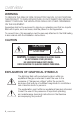
overview WARNING TO REDUCE THE RISK OF FIRE OR ELECTRIC SHOCK, DO NOT EXPOSE THIS PRODUCT TO RAIN OR MOISTURE. DO NOT INSERT ANY METALLIC OBJECT THROUGH THE VENTILATION GRILLS OR OTHER OPENNINGS ON THE EQUIPMENT. Apparatus shall not be exposed to dripping or splashing and that no objects filled with liquids, such as vases, shall be placed on the apparatus. To prevent injury, this apparatus must be securely attached to the Wall/ceiling in accordance with the installation instructions.
Class construction An apparatus with CLASS construction shall be connected to a MAINS socket outlet with a protective earthing connection. Batteries(battery pack or batteries installed) shall not be exposed to excessive heat such as sunshine, fire or the like. Disconnection Device Disconnect the main plug from the apparatus, if it’s defected. And please call a repair man in your location. When used outside of the U.S., it may be used HAR code with fittings of an approved agency is employed.
overview Please read the following recommended safety precautions carefully. yy Do not place this apparatus on an uneven surface. yy Do not install on a surface where it is exposed to direct sunlight, near heating equipment or heavy cold area. yy Do not place this apparatus near conductive material. yy Do not attempt to service this apparatus yourself. yy Do not place a glass of water on the product. yy Do not install near any magnetic sources. yy Do not block any ventilation openings.
CONTENTS overview installation & connection 25 network connection and setup 40 11 13 16 19 22 25 27 30 32 33 40 41 42 43 44 45 49 50 52 52 Important Safety Instructions Product Features Recommended PC Specifications Recommended Micro SD/SDHC/ SDXC Memory Card Specifications What’s Included At a Glance (SNB-5003) At a Glance (SNB-5004) At a Glance (SND-5083) At a Glance (SND-5084) Mounting the Lens (SNB-5003/SNB-5004) Installation (SND-5083/SND-5084) Inserting/Removing a Micro SD Memory Card Memory C
overview web viewer 53 55 56 59 61 64 Connecting to the Camera Login Installing Silverlight Runtime Installing STW WebViewer Plugin Using the Live Screen Playing the recorded video setup screen 70 70 91 102 118 Setup Video & Audio Setup Network Setup Event Setup System Setup appendix 125 130 133 135 Specification Product Overview Troubleshooting Open Source Announcement 53 70 125 8_ overview
Product Features English _9 ● overview •• HD Video Quality •• Multi-Streaming This network camera can display videos in different resolutions and qualities simultaneously using different CODECs. •• Web Browser-based Monitoring Using the Internet web browser to display the image in a local network environment.
overview Recommended PC Specifications •• CPU : Intel Core 2 Duo 2.4 GHz or higher (for using 1280x1024 30 fps) Intel Core i7 2.8 GHz or higher (for using 1280x1024 60 fps) `` Web Plug-in is optimized to SSE 4.1 Instruction Set. •• Operating System : Windows XP, VISTA, 7, 8, Mac OS X 10.7 •• Resolution : 1280X1024 pixels or higher (32 bit color) •• RAM : 2GB or higher •• Web Browser : Microsoft Internet Explorer (Ver. 10, 9, 8, 7), Mozilla Firefox (Ver.
What’s Included Please check if your camera and accessories are all included in the product package.
overview Appearance Item Name Quantity Description Model Name C Mount Adapter 1 Used to install the C Mount camera lens SNB-5003/ SNB-5004 Automatic Iris Lens Connector 1 Useful for camera lens installation SNB-5003/ SNB-5004 6-position Terminal Block 1 Used for alarm in/out terminals SNB-5003/ SNB-5004 Power Terminal Block 1 Plugged in the power plug SND-5083/ SND-5084 Alarm Cable 1 Useful for alarm connection SND-5083/ SND-5084 Screw 2 Useful for installation on the ceiling, wal
At a Glance (SNB-5003) Front Side ● overview a b c Item Description a Mounting Bracket Screw Hole Used to fix the camera on a mounting bracket. `` The screw size : It is the specification for the screws used to fasten the camera to the support. 1/4" - 20 UNC L : 4.5mm±0.2mm (ISO Standard) or 0.197" (ASA Standard) b Auto Iris Lens (Optional) Installed on the lens adaptor. c Auto Iris Lens Connector Used to supply power and output signal to control the iris of the lens.
overview Rear Side a b c i h d g e f Item a Micro SD Memory Card Compartment b Audio terminal Description Compartment for the Micro SD memory card. AUDIO OUT Used to connect to speakers. AUDIO IN Used to connect to a microphone. The button restores all camera settings to the factory default. Press and hold for about 5 seconds to reboot the system.
Item Description Power Port Used to plug the power cable. f Network Port Used to connect the PoE or Ethernet cable for network connection. g h Alarm I/O Port Test Monitor Out ALARM IN Used to connect the alarm input sensor or external day/ night sensor. ALARM OUT Used to connect the alarm output signal. GND Used for earth-grounding. RS-485+ RS-485 Data line RS-485- RS-485 Data line Output port for test monitoring the video output.
overview At a Glance (SNB-5004) Front Side a b c Item Description a Mounting Bracket Screw Hole Used to fix the camera on a mounting bracket. `` The screw size : It is the specification for the screws used to fasten the camera to the support. 1/4" - 20 UNC L : 4.5mm±0.2mm (ISO Standard) or 0.197" (ASA Standard) b Auto Iris Lens (Optional) Installed on the lens adaptor. c Auto Iris Lens Connector Used to supply power and output signal to control the iris of the lens.
Rear Side a b c d e h f ● overview j i g Item a Micro SD Memory Card Compartment b Audio terminal Description Compartment for the Micro SD memory card. AUDIO OUT Used to connect to speakers. AUDIO IN Used to connect to a microphone. The button restores all camera settings to the factory default. Press and hold for about 5 seconds to reboot the system. c Reset Button d Focus Adjustment Button J If you reset the camera, the network settings will be adjusted so that DHCP can be enabled.
overview Item Description e Lightning protective grounding port Used to discharge the lightning current safely outside in order to protect the camera. f Power Port Used to plug the power cable. g Network Port Used to connect the PoE or Ethernet cable for network connection. h i Alarm I/O Port Test Monitor Out ALARM IN Used to connect the alarm input sensor or external day/ night sensor. ALARM OUT Used to connect the alarm output signal. GND Used for earth-grounding.
At a Glance (SND-5083) Appearance ● overview a b Item Description a Dome cover Case cover used to protect the lens and the main unit. b Camera Case Housing part that covers the camera body.
overview Components a b c d e f g h AUDIO OUT 20_ overview AUDIO IN i jk l
Item Description Internal Cover It is a cover to protect the main body. b Lens Lens for the camera. c Focus Adjusting Lever Turn it left and right to adjust the lens focus and rotate it clockwise to fix it. d Zoom Adjusting Lever It can be used to adjust or fix the lens zoom. The button restores all camera settings to the factory default. Press and hold for about 5 seconds to reboot the system.
overview At a Glance (SND-5084) Appearance a b Item Description a Dome cover Case cover used to protect the lens and the main unit. b Camera Case Housing part that covers the camera body.
Components a ● overview b c d e f g AUDIO IN AUDIO OUT h ij k English _23
overview Item Description a Internal Cover It is a cover to protect the main body. b Lens Lens for the camera. c Zoom/Focus Control Button T Zoom in (Tele) N Focusing on a near object (Near) W F Focus Control Zoom out (Wide) Focusing on a far object (Far) Press this button for automatic focus control. The button restores all camera settings to the factory default. Press and hold for about 5 seconds to reboot the system.
installation & connection Mounting the Lens (SNB-5003/SNB-5004) Disconnect the power before proceeding. Mounting the CS lens on a camera Turn the CS lens clockwise to attach it. CS Lens Mounting the C lens on a camera Turn the C mount adapter included in the product package clockwise and turn the C lens clockwise. C Lens English _25 ● installation & connection C lens and CS lens are not included in the product package.
installation & connection Connecting the Auto Iris Lens connector Plug the iris connector of the lens in the camera connecting groove. Focusing Select a target to film, turn the zoom lever of the lens to adjust the magnification and then focus the lens so that target is clearly displayed. focusing with the zoom lever of the lens, press the [FOCUS] button on the rear of the camera MM `` After to adjust the lens even more clearly. (It is applicable only to the SNB-5004 model.
Installation (SND-5083/SND-5084) Ensure you read out the following instructions before installing the camera: •• It must be installed on the area (ceiling or wall) that can withstand 5 times the weight of the camera including the installation bracket. •• Stuck-in or peeled-off cables can cause damage to the product or a fire. •• For safety purposes, keep anyone else away from the installation site. And put aside personal belongings from the site, just in case. Disassembling 1.
installation & connection Installation 28_ installation & connection T ON FR P TO W F ET R ES T N AF VI 1. ALARM 2. ALARM OUT IN 3. GND JJ `` Pay attention to the direction for assembly. 1 2 3 5. Fasten the dome case (dome cover + camera case) to the main body as shown in the figure. + - 4. Refer to “Adjusting the monitoring direction for the camera” to adjust the lens in a desired direction. (page 29) 12V 3. Connect the camera internal terminal with the corresponding cable. DC 2.
Adjusting the monitoring direction for the camera (SND-5083/ SND-5084) ET AF VI 1. ALARM 2. ALARM OUT IN 3. GND R ES 1 2 3 W + - N 12V T ON FR P TO T DC F ● installation & connection D EO Pan Tilt Lens rotation `` Adjusting the monitoring direction You can adjust the camera direction only when the camera is fixed on the ceiling. Where, rotating the camera unit to the left or right is called Pan, adjusting the tilt is called Tilt, and turning the lens on its axis is called Rotation.
installation & connection Inserting/Removing a Micro SD Memory Card JJ `` Disconnect the power cable from the camera before inserting the Micro SD memory card. `` Do not insert the Micro SD memory card while it’s upside down by force. Otherwise, it may damage the Micro SD memory card. Inserting a Micro SD Memory Card Push the Micro SD memory card in the direction of the arrow shown in the diagram.
Removing a Micro SD Memory Card Gently press down on the exposed end of the memory card as shown in the diagram to eject the memory card from the slot. ● installation & connection AUDIO IN AUDIO OUT AUDIO IN AUDIO OUT too hard on the Micro SD memory card can cause the card to shoot out uncontrollably JJ `` Pressing from the slot when released.
installation & connection Memory Card Information (Not Included) What is a memory card? The memory card is an external data storage device that has been developed to offer an entirely new way to record and share video, audio, and text data using digital devices. Selecting a memory card that’s suitable for you Your camera supports Micro SD/SDHC/SDXC memory cards. You may, however, experience compatibility issues depending on the model and make of the memory card.
Connecting with other Device ● installation & connection Monitor to install Grounding cable Power Ethernet Monitor to install AUDIO IN Ethernet Power CVBS out terminal of the product is provided for easier installation, and is not recommended JJ `` The for monitoring purposes.
installation & connection Ethernet Connection Connect the Ethernet cable to the local network or to the Internet. Power Supply (SNB-5003/SNB-5004) Use the screwdriver to connect each line (+, –) of the power cable to the corresponding power port of the camera. PoE and DC 12V powers are both applied, the device will be operated by the initially applied JJ `` Ifpower source. -- You can also use a router featuring PoE to supply power to the camera. -- Use PoE that is compliant with the IEEE802.
Power Cable Specification for Each Model In case of DC 12V Input: Wire Type (AWG) SNB-5004 SND-5083 SND-5084 In case of AC 24V Input: Wire Type (AWG) Cable Length (Max.) SNB-5003 SNB-5004 Network Cable Specification Item Connector Ethernet Cable Max Distance PoE Support #22 #20 #18 20m 32m 50m 24m 38m 60m #22 #20 #18 34m 55m 88m Contents RJ45 10/100Base-T UTP Category 5e 100M IEEE 802.
installation & connection Connecting to Audio Input/Output Speaker Microphone Microphone Amp Microphone Speaker PC Network Amp Speaker AUDIO OUT 36_ installation & connection AUDIO OUT Speaker AUDIO IN Amp AUDIO IN Speaker Amp Microphone Microphone
1. Connect the AUDIO IN port of the camera with the microphone or LINE OUT port of the amplifier that the microphone is connected to. MM `` As a microphone is built in, you can use the built-in microphone instead of an external one. 3. Check the specifications for audio input. •• Audio Codec -- Audio In : G.711 PCM (Bit Rate: 64kbps / Sampling Frequency: 8kHz), G.726 ADPCM (Bit Rate: 16Kbps, 24Kbps, 32Kbps, 40Kbps / Sampling Frequency: 8kHz) -- Audio Out : G.
installation & connection Connecting an external RS-485 device (SNB-5003/SNB-5004) Connect the camera with an external device using the [RS-485 +, -] ports. You can control the pan/tilt operations of the camera via RS-485 communications. `` The GND connection is recommended for RS-485 communications. If you encounter a communication failure, connect the GND pin as appropriate to correct the GND level between camera and external device.
To connect the alarm out If devices (e.g., flashing light and siren) that exceed the voltage and current specifications are connected by using the open collector method, it may cause malfunction. Alarm Out Wiring Diagram (SNB-5003/SNB-5004) Inside of the camera DC 5V or 3.
network connection and setup You can set up the network settings according to your network configurations. Connecting the Camera Directly to Local Area Networking Connecting to the camera from a local PC in the LAN 1. Launch an Internet browser on the local PC. 2. Enter the IP address of the camera in the address bar of the browser.
Connecting the Camera Directly to a DHCP Based DSL/Cable Modem DSL/Cable Modem External Remote PC DDNS Server (Data Center, KOREA) 1. Connect the user PC directly with the network camera. 2. Run the IP Installer and change the IP address of the camera so that you can use the web browser on your desktop to connect to the Internet. 3. Use the Internet browser to connect to the web viewer. 4. Move to [Setup] page. 5. Move to [Network] – [DDNS] and configure the DDNS settings. 6.
network connection and setup Connecting the Camera Directly to a PPPoE Modem INTERNET Camera PPPoE Modem External Remote PC DDNS Server (Data Center, KOREA) 1. Connect the user PC directly with the network camera. 2. Run the IP Installer and change the IP address of the camera so that you can use the web browser on your desktop to connect to the Internet. 3. Use the Internet browser to connect to the web viewer. 4. Move to [Setup] page. 5. Move to [Network] – [DDNS] and configure the DDNS settings.
Connecting the Camera to a Broadband Router with the PPPoE/Cable Modem This is for a small network environment such as homes, SOHO and ordinary shops. INTERNET Camera Broadband Router PPPoE or Cable Modem Local PC PPPoE or Cable Modem External Remote PC DDNS Server (Data Center, KOREA) Configuring the network settings of the local PC connected to a Broadband Router Configuring the network settings of the local PC connected to a Broadband Router, follow the instructions below.
network connection and setup Buttons used in IP Installer a b c d hi Item e j f g k l m Description a Device Name Model name of the connected camera. Click the column to sort the list by model name. However, search will be stopped if clicked during the search. b Alias This function is not currently implemented. c Mode Displays either , or for the current network connection status.
Item Description URL DDNS URL address enabling access from the external Internet. However, this will be replaced with the of the camera if DDNS registration has failed. h IPv4 Scans for cameras with the IPv4 setting. i IPv6 Scans for cameras with the IPv6 setting. Activated in an IPv6 compliant environment only. j Search Scans for cameras that are currently connected to the network. However, this button will be grayed out if neither IPv4 nor IPv6 is checked.
network connection and setup 3. In the
pane, provide the necessary information. •• MAC (Ethernet) Address : The MAC address imprinted on the camera label is automatically displayed and requires no user setting. related parameters can be set only MM `` IPwhen DHCP is not checked. If not using a Broadband Router For setting , , and , contact your network administrator. 4. In the pane, provide necessary information.If using a Broadband Router settings may differ depending on the connected Broadband Router model. MM `` The For more information, refer to the user manual of the applicable router. `` For more information about port forwarding of the broadband router, refer to “Port Range Forward (Port Mapping) Setup”. (Page 50) If the Broadband Router has more than one camera connected Configure the IP related settings and the Port related settings distinctly with each other.
network connection and setup Auto Network Setup Run to display the camera search list. At the initial startup, both [Auto Set] and [Manual Set] will be grayed out. cameras found with the IPv6 setting, these buttons will be grayed out as the cameras do not MM `` For support this function. 1. Select a camera in the search list. Check the MAC address of the camera on the camera’s label. Both the [Auto Set] and [Manual Set] buttons will be activated. 2. Click [Auto Set].
Dynamic IP Setup Dynamic IP Environment Setup Checking the Dynamic IP 1. Run the IP Installer on the user’s local computer. Cameras allocated with address are shown in the list. 2. Select a camera from the search result. 3. Click the [Manual Set] button and check the camera’s address. If you uncheck , you can change IP to .
network connection and setup Port Range Forward (Port Mapping) Setup If you have installed a Broadband Router with a camera connected, you must set the port range forwarding on the Broadband Router so that a remote PC can access the camera in it. Manual Port Range Forwarding 1. From the Setup menu of the Broadband Router, select - . For setting the port range forward for a third-party Broadband Router, refer to the user guide of that Broadband Router. 2.
Setting up Port Range Forward for several network cameras When several network cameras are connected to one Broadband Router device, you should forward the TCP 943 port of the router to the TCP 943 port of a connected camera. •• TCP 943 port is a port for the Silverlight policy server of a camera. •• You can set a rule of Port Forwarding on the Broadband Router device through its configuration web page. •• You cannot change the Silverlight policy server port of a camera.
network connection and setup Connecting to the Camera from a Shared Local PC 1. Run the IP Installer. It will scan for connected cameras and display them as a list. 2. Double-click a camera to access. The Internet browser starts and connects to the camera. to the camera can also be gained by typing the camera's IP address in the address bar of MM `` Access the Internet browser.
web viewer Connecting to the Camera Normally, you would 1. Launch the Internet browser. ● web viewer 2. Type the IP address of the camera in the address bar. ex) • IP address (IPv4) : 192.168.1.100 http://192.168.1.100 - the Login dialog should appear. • IP address (IPv6) : 2001:230:abcd: ffff:0000:0000:ffff:1111 http://[2001:230:abcd:ffff:0000 :0000:ffff:1111] - the Login dialog should appear. If the HTTP port is other than 80 1. Launch the Internet browser. 2.
web viewer Connecting via UPnP 1. Run the client or operating system in support of the UPnP protocol. 2. Click the camera name for search. In the Windows operating system, click the camera name searched from the network menu. -- The login window is displayed. Connecting via Bonjour 1. Run the client or operating system in support of the Bonjour protocol. 2. Click the camera name for search. In the Mac operating system, click the camera name searched from the Bonjour tab of Safari.
Login Whenever you access the camera, the login window appears. Enter the User ID and password to access the camera. ● web viewer 1. Enter “admin” in the input box. The administrator ID, “admin”, is fixed and can not be changed. 2. Enter “4321” in the input box. If the password is changed, enter the changed password instead. 3. Click [OK]. If you have logged in successfully, you will the Live Viewer screen. MM `` The default user ID is “admin”, and the default password is “4321”.
web viewer Installing Silverlight Runtime If your PC has not installed Silverlight Runtime or has just installed an old runtime version, you will be redirected to the Silverlight Runtime installation page automatically when accessing the web viewer. To install on Windows OS 1. Click . 2. When the file download dialog pops up, click . 3. When the download is completed, click . 4. The Silverlight Runtime installation page will be displayed.
To install on MAC OS 1. Run the file trailing with “.dmg”. ● web viewer 2. Run the install package file automatically created, ending with “.pkg”. 3. Click . 4. Select your language on the language selection screen, and click .
web viewer 5. Click . 6. Click . 7. Enter the password of the account currently logged in, and click and continue. 8. Once completed, click .
Installing STW WebViewer Plugin If connecting to a camera for the first time, you will see the installation message. Then, install the required WebViewer Plugin to access the camera and control the video from it in real time. the plug-in installation file download status is suspended at 99% in the Internet Explorer JJ `` Ifbrowser, retry it after selecting “Release SmartScreen filter” in “Tool SmartScreen filter”. 2. Click [Run] in the message window. 3.
web viewer 5. Click [OK]. The old version of Web Viewer Plug-in is deleted. 6. Click [Install] to begin installation of the Web Viewer Plug-in. 7. Click [Finish]. STW Web Viewer Plug-in installation is completed.
Using the Live Screen a b c d ● web viewer e f g h i j k l m Item Description a b c Monitoring Move to the monitoring screen. Playback Switch to the monitoring screen that plays recording data in the Micro SD memory. Setup Move to the Setup screen. d Viewer Screen e Profile type f Screen Optimization g Fix the resolution Displays the Live video on the screen. `` You can use the mouse wheel to activate the digital zooming in Viewer screen.
web viewer Item h i j k Description Full Screen Switch the current video to the maximum size of the monitor. Capture Saves the snapshot as an image file in the .bmp or .jpg format. Audio/Microphone Enable Audio and Microphone are control the Audio volume. Control `` Only the Audio volume can be controlled. Alarm output l External PTZ m Hide the context menu Activate the Alarm Out port. Connect the external PTZ to the RS-485 terminal and control the PTZ camera lens direction with the arrow keys.
To fit the full screen 1. Click the [Full Screen ( )] button. 2. This will fit the Viewer to the full screen. MM `` For the Internet Explorer and Google Chrome browser, you can switch to the full screen. To Use Audio 1. Click [Audio ( 2. Use [ )] icon to activate audio communication. ] bar to control the volume. there is no sound from pulling in and out the audio jack while it is in operation, click the MM `` If[Audio ( )] icon to enable it again.
web viewer Playing the recorded video you can play the video, you must configure the record settings. For details on record settings, MM `` Before refer to “Storage”. (page 103) Name of event search screen and its function a b c Item Description a Set the search date and time from the data saved in the Micro SD memory Search range setting card. b Search event setting Set the event type to search within the search period. c Event search 64_ web viewer Run the event search.
To play the content after searching by event 1. Click the [Playback ( )] button. 2. Specify the start time and end time of your search. ● web viewer 3. Select an event type for your search within the specified period. 4. Click the [Event search] button. The search results will be displayed in the list. more than 800 events are recorded MM `` Ifwithin the search period, your search will be limited up to the date when the 800th event is recorded.
web viewer Name of time search screen and its function b c d e f g h a Item Description a Time bar The section in the specific period is played by moving the time bar. b Search date setting `` Dates for which there is video in the Micro SD memory card are c Screen optimization The camera image is converted to fit the Web browser window. d Fix the resolution Regardless of the resolution setup configured in the camera, it sets the resolution to 800x600.
To play after searching by time 1. Click [Time Search ( )]. ● web viewer 2. Click a desired date in the calendar. The video on the specified date will be played. 3. If the video playback is stopped, select a time and click [Play ( )]. The video on the selected time will be played. 4. While the video is being played, the recording time for the current video will be shown. 5. Search for the video forward or backward, and control the play speed.
web viewer To back up the searched video 1. During playback, click [ ] on the scene to back up. The scheduling window for backup start and end time appears. ] button. 2. Click [ The Save As window appears. 3. Confirm the save path and click [Save] button. The screenshot will be backed up to the specified path. To play the backup video The backed up images are saved in an .avi format. Gom Player, VLC Player, and Window Media Player are recommended as the media player compatible with this format.
To Play an AVI File JJ `` The AVI file does not contain the recording time data. separating the micro SD memory card, set the to in the “Setup JJ `` Before Event Storage” menu. 2. Insert the micro SD memory card into the PC. 3. Play the AVI file in the “\ch00\img\ YYYY_MM_DD” directory, using a media player. file name begins with “01.avi” and MM `` The the file number increments by 1. `` Once corrupted, the data in the micro SD memory card cannot be replayed in Web Viewer Playback.
setup screen Setup You can configure the video & audio, network, event and system settings of the camera in the network. 1. In the Live screen, click [Setup ( 2. The Setup screen appears. )]. Silverlight 5.0 or higher is required to be installed on the PC for setup pages that provide JJ `` Microsoft preview video. If not installed already, automatically moves to the Silverlight setup. Video & Audio Setup Video profile 1. From the Setup menu, select the )> tab.
•• E-mail/FTP profile : Video profile to be transferred to the specified email or FTP site. `` Only the MJPEG codec can be set as the E-mail/FTP profile. 6. According to your situation, set ATC (Auto Transmit Control) mode. •• ATC mode : It adjusts the video properties according to the variance in the network bandwidth, controlling the bit rate. Adjusting the bit rate depends on the ATC mode. -- Control framerate : Reduce the frame rate if the network bandwidth drops down.
setup screen To Add/Change the Video Profile The profile setup can be added or modified to accommodate various profiles depending on the recording conditions. 1. Select one from the
What is GOV length? GOV(Group of Video object planes) is a set of video frames for H.264 compression, indicating a collection of frames from the initial I-Frame (key frame) to the next I-Frame. GOV consists of 2 kinds of frames: I-Frame and P-Frame. I-Frame is the basic frame for the compression, also known as Key Frame, which contains one complete image data. P-Frame contains only the data that has changed from the preceding I-Frame. For H.264 codec, you can determine the GOV length.
setup screen To Use Crop Encoding 1. Select
Video setup 1. From the Setup menu, select the
setup screen Audio setup You can configure the I/O settings of the audio source from the camera. 1. From the Setup menu, select the
Camera setup You can change the camera settings according to the environment where the camera is located. ● setup screen 1. From the Setup menu, select the
setup screen To Set SSDR (Samsung Super Dynamic Range) In a scene where the difference between bright and dark is severe, you can increase the brightness of the dark area alone to regulate the overall brightness. 1. Select . 2. Set to . 3. Configure the and settings as necessary. •• Level : Adjust the level of the dynamic range. •• D-Range : Select the amplitude area of the dynamic range.
To Set BLC You can specify a desired area on the video manually and set the area to be displayed more clearly. 1. Select . ● setup screen 2. Set to . 3. Set . You can change the level to adjust the brightness of the monitoring area. 4. Set the levels to specify the target area. BLC is set, the green box is JJ `` When displayed on the screen for 15 seconds.
setup screen To Set Exposure (SNB-5003/SNB-5004) You can adjust the exposure level of the camera. 1. Select . 2. Select each item and set it properly. •• Brightness : Adjust the screen brightness. •• Minimum shutter : The limit of the longest exposure time. `` Shutter is the mode to set up the range of the sensor exposure time which will specify the upper and lower limits for the electronic shutter movement.
To Set Exposure (SND-5083) You can adjust the exposure level of the camera. 1. Select . `` The framerate may be reduced in the dark condition if Shutter has a lower value than specified in the Sensor mode. •• Maximum shutter : The limit of the shortest exposure time. •• Anti flicker : It prevents screen flickering incurring from the dissonance between the surrounding lighting and the frequency. •• SSNR : Select Able or Disable for the video noise elimination function.
setup screen To Set Exposure (SND-5084) You can adjust the exposure level of the camera. 1. Select . 2. Select each item and set it properly. •• Brightness : Adjust the screen brightness. •• Minimum shutter : The limit of the longest exposure time. `` Shutter is the mode to set up the range of the sensor exposure time which will specify the upper and lower limits for the electronic shutter movement.
To Set Day/Night (SNB-5003/SND-5083/SND-5084) 1. Select . ● setup screen 2. Select each item and set it properly. •• Mode: Mode is used to adjust the color of Color or Black and White. -- Color : The video is always output in color. -- B/W : The video is always output in black and white. -- Auto : Normally, it is set to Color but to B&W under low luminance at night. `` If AGC of the menu is set to , the day/night mode cannot be set to .
setup screen To Set Day/Night (SNB-5004) 1. Select . 2. Select each item and set it properly. •• Mode: Mode is used to adjust the color of Color or Black and White. -- Color : The video is always output in color. -- B/W : The video is always output in black and white. -- Auto : Normally, it is set to Color but to B&W under low luminance at night. `` If AGC of the menu is set to , the day/night mode cannot be set to .
To Setup Special 1. Select . -- Auto : The image is automatically compensated according to the foggy level. Adjust to be more effective. -- Manual : The user manually sets the amount of compensation for each image. mode is set to , the performance is proportional to the fog level. To keep JJ `` Ifthethesetdefog defog level without regard to the fog level, set the defog mode to . `` If the manual defog level is high in a thin fog, the image may become too dark.
setup screen To Set OSD 1. Select . 2. Select each item and set it properly. •• Title overlay : It specifies if the camera name shall be displayed on the screen. •• Camera title : It specifies the name of the camera to be displayed on the screen. •• Title position X, Y : It specifies the position of the camera name on the screen. •• Time display : Specify the use of time display on the screen. •• Date notation : Specify the date format that will be displayed on the screen.
Focus setup (SNB-5004) You can adjust the focus of video image. 1. From the Setup menu, select the
setup screen Focus setup (SND-5084) You can adjust the focus and zoom ratio of video image. 1. From the Setup menu, select the
External PTZ setup (SNB-5003/SNB-5004) Configure the connection settings to the external pan/tilt receiver so that you can control the PTZ operations via the receiver connected to the RS-485 port of the camera. )> tab ● setup screen 1. Select the
setup screen 5. Adjust the direction. •• [Change direction to ( )/( )/( )/( )/( )/( )/( )/( )] : The camera direction is adjusted. •• [Moving speed control ( )] : The bigger the number is, the faster the moving speed becomes. 6. Set the zoom and focus. •• [Zoom In ( )] : Zooms in the screen. •• [Zoom Out ( )] : Zooms out the screen. •• [Adjust Focus ( / )] : Adjusts the focus in the screen. •• [Zoom Speed Control ( )] : The bigger the number is, the faster the zoom speed becomes. 7. Set the preset.
Network Setup Interface 2. Click . 3. Set the and as necessary. •• IP type : Select an IP connection type. -- Manual : Specify the IP address, Subnet mask, Gateway, DNS1, and DNS2. -- DHCP : Specify the DNS1 and DNS2. -- PPPoE : Specify the DNS1, DNS2, ID and Password. `` If you set it to , you should specify the IP, Subnet mask, Gateway, DNS 1 & 2 manually. •• MAC address : Shows the MAC address. •• IP address : Displays the current IP address.
setup screen Port 1. From the Setup menu, select the tab. 2. Click . 3. Type in each item in the Port menu as necessary. `` When setting your ports, you cannot use port numbers such as 0~1023, 3702 or 49152. •• HTTP port : HTTP port used to access the camera via the web browser. The default is 80(TCP). `` Setting the HTTP port for Safari and Google Chrome browsers to 65535 is not allowed by security policy.
DDNS DDNS is an abbreviation of Dynamic Domain Name Service that converts the IP address of a camera into a general Host Name so that the user can easily remember it. 2. Click . 3. Select the connection type. 4. Type in the DDNS items according to the selected type. •• Samsung DDNS : Select this if you use the DDNS server provided by Samsung Techwin. -- Product ID : Enter the product ID that is registered with the Samsung DDNS service.
setup screen Registering with DDNS To register your product with the Samsung DDNS 1. Visit the iPOLiS web site (www.samsungipolis.com) and sign in with a registered account. 2. From the top menu bar, select - . 3. Click [PRODUCT REGISTRATION]. 4. Enter the product ID. `` You must perform the duplicate check for the ID that you entered. 5. Select a and specify the . 6. Specify the product location with a description if necessary. 7.
To connect to the Samsung DDNS in camera setup 1. From the DDNS setup page, set to . ● setup screen 2. Provide the that you registered product ID with the DDNS site. )]. 3. Click [Apply ( When the connection is successfully made, you will see the message of <(Success)> on the screen. Configuring public DDNS in Camera Settings 1. Open the DDNS settings page and select for . 2. Enter the corresponding site’s host name, user name and password.
setup screen IP filtering You can create a list of IPs that you want to grant or deny access to them. 1. From the Setup menu, select the tab. 2. Click . 3. Select . •• Deny : If selecting this, access from those IPs that are added to the filtering will be restricted. •• Allow : If selecting this, access from only those IPs that are added to the filtering will be accepted. 4. Click the [Add ( )] button. The IP list will be created. 5.
SSL You can select a secure connection system or install the public certificate for this purpose. 2. Click . 3. Select a secure connection system. `` To access the camera using HTTPS mode, you have to type the IP address for the camera in the form of “https://”. If you failed to configure the Web viewer settings in HTTPS mode with Internet Explorer, edit the Internet options as follows:
setup screen 802.1x When connecting network, you can choose whether using 802.1x protocol, and then install the certification. 1. From the Setup menu, select the tab. 2. Click <802.1x>. 3. Set the . •• Enable IEEE 802.1x : Specify the use of the 802.1x protocol. •• EAPOL version : Select version 1 or 2. •• ID : Enter the client certificate ID. •• Password : Enter the client private key password.
QoS You can specify the priority to secure a stable transfer rate for a specific IP. 1. From the Setup menu, select the tab. ● setup screen 2. Click . )] button. 3. Click the [Add ( The IP list will be created. 4. Enter an IP address to which you will apply QoS. default prefix for IPv4 is 32; MM `` The For DSCP, the default is set to 63. `` Only the IP addresses that are set to
setup screen •• Enable SNMP Trap : SNMP trap is used to send important events and conditions to the Admin. -- Community : Enter the trap community name to receive messages. -- IP address : Enter the IP address to which messages will be sent. -- Authentication failure : It specifies whether an event shall be generated when the community information is invalid. -- Network connection : It specifies whether an event shall be generated when the network disconnection is restored.
UPnP discovery Cameras can be automatically searched in the client and operating system in support of the UPnP protocol. ● setup screen 1. From the Setup menu, select the tab. 2. Click . 3. Set the . •• UPnP discovery : It specifies Able or Disable for UPnP Discovery. •• Friendly name : Display the camera name. Friendly name is displayed in the format of SAMSUNG--.
setup screen Event Setup FTP / E-mail You can configure the FTP/E-mail server settings so that you can transfer the images taken with camera to your PC if an event occurs. 1. From the Setup menu, select the tab. 2. Click . 3. Select or and enter / select a desired value. •• FTP configuration -- Server address : Enter the IP address of the FTP server that you transfer the alarm or event images to.
4. When done, click [Apply ( )]. Storage You can set the record conditions or the use of recording for the Micro SD memory, check the size of stored data, or format the Micro SD memory itself. 1. From the Setup menu, select the tab. 2. Click . English _103 ● setup screen •• E-mail configuration -- Server address : Enter the IP address of the email server that you transfer the alarm or event images to. -- Use authentication : Select whether to use authorization.
setup screen To make recording on the Micro SD memory 1. Check the memory card’s size and size. 2. If there are sufficient free space, set the device to . Otherwise, check the stored data and if you find them not important, then click to format the Micro SD memory. `` Some frames may be skipped if the micro SD memory card operates at the lower speed than recommended. For more details, refer to “Recommended Micro SD/SDHC/SDXC Memory Card Specifications”.
Alarm input You can set the alarm input type, activation time, and operation mode. 1. From the Setup menu, select the tab. ● setup screen 2. Click . 3. Select from . 4. Set whether or not to . 5. Specify an input device. •• Type -- Normal open : It is normally open, but if it is closed, an alarm will be triggered. -- Normal close : It is normally closed, but if it is open, an alarm will be triggered. 6. Specify the .
setup screen 7. Specify an operation that will perform if an alarm occurs. •• FTP : Specify the use of FTP transfer in the alarm input setup. •• E-mail : Specify the use of email transfer in the alarm input setup. •• Record : Specify the use of recording in the alarm input setup. •• Alarm output : Select whether to set the alarm output if an alarm is incoming, and specify the alarm output time. •• Goto preset : Moves to the specified preset location when setting the alarm input.
Tampering detection You can set to detect tampering attempts and trigger events, such as sudden change of camera’s framing direction, blocked lens and other overall change of scenes from the video. ● setup screen 1. From the Setup menu, select the tab. 2. Click . 3. Select from . 4. Set whether or not to . 5. Set the tampering detection sensitivity. The higher the sensitivity, detects the minutest tampering attempts. 6.
setup screen Motion detection / Video analytics Events of motion detection and video analysis can be set to trigger event signal output. 1. From the Setup menu, select the tab. 2. Click . 3. Select from . 4. Set whether or not to . 5. According to your purpose, select from motion detection and intelligent video analysis. 6. Set , and .
detection and Video analytics cannot be used simultaneously. JJ ```` Motion Before using, set the minimum and maximum motion sizes to suit desired motion range to be detected. Detected size of an object may have difference with the actual size according to its shape. Up to 16 objects from the top side of the screen can be displayed. If camera is capturing a close object, the video analysis capability may degrade.
setup screen To use Motion detection It detects a motion that meets all conditions specified by sensitivity, size and area. 1. Select a motion detection mode. 2. Select tab to set the sensitivity level. You can set the sensor’s sensitivity to detect a motion out of the background from the monitoring video. a situation that definitely distinguishes JJ `` Inobjects out of backgrounds, set this to a low sensitivity level.
● setup screen 4. Select tab. You can specify an area on the screen to include or exclude the area to/from detection. You can specify up to 4 areas. •• Detection area : Sets the entire screen as excluded from detection, and adds specified area as motion detection area. Select 4 vertices in the image with your mouse to specify the detection area. •• Non detection area : Sets the entire screen as motion detection area, and excludes specified area as not to be detected.
setup screen To use Video analytics It detects event that meets all conditions specified by sensitivity, size and area and the event condition rules. 1. Select the video analysis mode. 2. Set , and . For further details on settings, refer to “To use Motion detection”. (Page 110~111) 3. Select tab. 4. Select the video analysis type. •• Passing, Entering/Exiting : Detects motions of passing, entering into or exiting from a virtual line specified by the user.
To set the video analysis rules `` Passing ● setup screen 1. Set the type to . 2. Set the event rule to . 3. On the screen, click on preferred starting and ending point of the virtual line, then a popup window appears. 4. Select the desired rule: •• Right: Detects motions of moving from the left to the right, over the virtual line. •• Left: Detects motions of moving from the right to the left, over the virtual line. 5. Click [OK]. 6.
setup screen `` Appearing (Disappearing) 1. Set the analysis type to . 2. Select the desired event rule: •• Defined area based rules : It detects event of appearing object that appears in the area and remaining for a certain time period while not passing through the area borders, and opposite case of disappearing of objects existed in the area. On the screen, click four vertices to define detection area. Select the from the popup.
Face detection You can set to detect recognized face and trigger an event accordingly. 1. From the Setup menu, select the tab. ● setup screen 2. Click . 3. Select from . 4. Set whether or not to . 5. Select tab to set the sensitivity level. `` As the sensitivity grows, face detection becomes more close and detailed. 6.
setup screen Audio detection You can set to detect sound over the specified level and trigger an event accordingly. 1. From the Setup menu, select the tab. 2. Click . 3. Select
Alarm output setup 1. From the Setup menu, select the tab. 3. Set the camera’s type of alarm output. `` If you change the alarm output type, the alarm out button on the monitoring page and alarm output type displayed on Event Setup page will be changed accordingly. •• Type -- Normal open : Considers “Open circuit” status of the sensor or alarm input device as normal, and triggers alarm event if becomes “Closed circuit” status.
setup screen System Setup Product information 1. From the Setup menu, select the tab. 2. Click . 3. Check the camera information, or provide details according to your network environment. •• Model : Model name of the product. •• Serial number : Product serial number. •• Device name : Provide a device name that will be displayed on the Live screen. •• Location : Specify the location where the camera is installed.
Date & Time 1. From the Setup menu, select the tab. 3. Specify the time and date that will be applied to the camera. •• Current system time : Displays the current time settings of your system. •• Timezone : Specify the local time zone based on the GMT. •• Use daylight saving time : If checked, the time will be set one hour before the local time zone for the specified time period. This option will be displayed only in areas where DST is applied.
setup screen User 1. From the Setup menu, select the tab. 2. Click . 3. Provide the necessary user information. •• Administrator password change : Change the password for the administrator. `` The default password can be exposed to a hacking thread so it is recommended to change the password after installing the product. Note that the security and other related issues caused by the unchanged password shall be responsible for the user.
Upgrade / Reboot 1. From the Setup menu, select the tab. 3. Select a desired item and set it appropriately. •• Upgrade : Performs upgrading the system. •• Factory default : Resets the system to the factory default. -- Except network parameter : Initialize all setup parameters except for network or lens setup. -- All : Resets all settings including the camera settings.
setup screen take a max of 20 minutes for the upgrade process. MM `` ItIf may you forcibly terminate the upgrade process, upgrade will not be completed properly. `` During restarting the system, accessing with web viewer will not be made. `` You can download the latest version from the Samsung web site (www.samsungcctv.com). To back up the current settings 1. Click [Backup]. The Save As dialog should appear. 2. Specify the backup path with a proper file name, and click [Save].
Log You can check the system log or event log. 1. From the Setup menu, select the tab. ● setup screen 2. Click . 3. Select a log type. •• System : You can check the system logs where any system changes are recorded including the time information. •• Event : You can check the event logs including the time information. 4. From the right log list, select an item to search for. •• If you select in the top left dropdown list, all logs for the applicable log type will be displayed.
setup screen Profile access You can check the profile information. 1. From the Setup menu, select the tab. 2. Click . •• Profile access : Show the information of the newly added profile. -- Profile : Show the information of the newly added codec. -- Bitrate(kbps) : Show both the actual bit rate and the set bit rate. -- Framerate(fps) : Show both the actual frame rate and the set frame rate. -- ATC(%) : Show the ATC status.
appendix Specification Items Effective Pixels 1.37M, 1,305(H) x 1,049(V) Min. Illumination S / N Ratio SND-5083 SND-5084 1.4M, 1,312(H) x 1,069(V) Progressive Color : 0.05 Lux (1/30sec, F1.2, 50IRE), 0.0008 Color : 0.05 Lux (1/30sec, F1.2, 50IRE), 0.0008 Lux Lux (2sec, 50IRE) (2sec, 50IRE) B/W : 0.05 Lux B/W : 0.005 Lux (1/30sec, F1.2, 50IRE) (1/30sec, F1.2, 50IRE) 50dB Video Out CVBS : 1.
appendix Items Lens Pan / Tilt / Rotate Lens Type SNB-5003 DC Auto Iris - 0° ~ +354° C/CS Mount Tilt Range - Rotate Range Camera Title Day & Night Backlight Compensation SND-5083 Manual / DC Auto Iris, P-Iris Mount Type Pan Range Description SNB-5004 - Board-in type 0° ~ +67° 0° ~ +355° Off / On (Displayed up to 40 characters) Auto (SW) / Color / B/W / External / Auto (ICR) / Color / B/W / External / Schedule Schedule Off / BLC Wide Dynamic Range 130dB Contrast Enhancement SSDR (Samsun
Items Alarm I/O Input 1ea / Output 1ea Audio out Serial Interface Alarm Triggers SND-5083 SND-5084 Tampering, Virtual Line, Enter/Exit, Appear / Disappear, Audio Detection, Face Detection Selectable (Mic IN/Line IN), Max output level: 1 Vrms Supply voltage: 2.5VDC(4mA), Input impedance: approx. 2K Ohm Line out (3.
appendix Items Bitrate Control Method SNB-5003 H.264 : CBR or VBR Description SNB-5004 SND-5083 SND-5084 MJPEG : VBR Streaming Capability Multiple Streaming (Up to 10 Profiles) Audio Compression Format G.726 (ADPCM) 8KHz, G.711 8KHz G.711 µ-law /G.726 Selectable G.
Items Webpage Language Network Web Viewer Central Management Software Environmental Electrical SND-5083 SND-5084 SUNAPI 2.0 SVNP 1.2 English, French, German, Spanish, Italian, Chinese, Korean, Russian, Japanese, Swedish, Denish, Portuguese, Czech, Polish, Turkish, Rumanian, Serbian, Dutch, Croatian, Hungarian, Greek, Norway, Finland Supported OS : Windows XP / VISTA / 7 / 8, MAC OS X 10.7 Supported Browser : Microsoft Internet Explorer (Ver. 7~10), Mozilla Firefox (Ver. 9~19), Google Chrome (Ver.
appendix Product Overview SNB-5003 136.2(5.36") Unit : mm (inch) 66.6(2.62") 73.1(2.88") Ø 6.5 HOLE (Ø 0.26") 14 (0.55") 56.1 (2.
SNB-5004 Unit : mm (inch) 147.8(5.82") ● appendix 66.6(2.62") 73.1(2.88") Ø 6.5 HOLE (Ø 0.26") Ø 1/4'-20 UNC-2B 14 (0.55") 67.7 (2.
appendix SND-5083/SND-5084 Unit : mm (inch) 5") 4.6 8( 1 1 107.6 (4.24") Ø 132.1 (5.2") Ø 97 (3.
Troubleshooting PROBLEM yy Check to make sure that the camera’s Network settings are appropriate. yy Check to make sure that all network cables have been connected properly. yy If connected using DHCP, verify that the camera is able to acquire dynamic IP addresses without any problem. yy If the camera is connected to a Broadband Router, verify that port forwarding is properly configured. yy Connected Viewers become disconnected upon any change to camera or network configurations.
appendix PROBLEM of is set to , but no notification e-mail reaches me even when an analysis event had occurred. SOLUTION yy Verify the settings in the following sequence: A. Check settings. B. The should be set to . C. Check if the option of menu is checked to use.
Open Source Announcement GPL/LGPL software license The software included in this product contains copyrighted software that is licensed under the GPL/LGPL. You may obtain the complete Corresponding Source code from us for a period of three years after our last shipment of this product by sending email to help.cctv@samsung.com. If you want to obtain the complete Corresponding Source code in the physical medium such as CD-ROM, the cost of physically performing source distribution might be charged.
GNU GENERAL PUBLIC LICENSE Version 2, June 1991 Copyright (C)1989, 1991 Free Software Foundation, Inc. 51 Franklin Street,Fifth Floor, Boston, MA 02110-1301, USA Everyone is permitted to copy and distribute verbatim copies of this license document, but changing it is not allowed. Preamble The licenses for most software are designed to take away your freedom to share and change it.
3.
NO WARRANTY 11. BECAUSE THE PROGRAM IS LICENSED FREE OF CHARGE, THERE IS NO WARRANTY FOR THE PROGRAM, TO THE EXTENT PERMITTED BY APPLICABLE LAW. EXCEPT WHEN OTHERWISE STATED IN WRITING THE COPYRIGHT HOLDERS AND/OR OTHER PARTIES PROVIDE THE PROGRAM “ASIS” WITHOUT WARRANTY OF ANY KIND, EITHER EXPRESSED OR IMPLIED, INCLUDING, BUT NOT LIMITED TO, THE IMPLIED WARRANTIES OF MERCHANTABILITY AND FITNESS FOR A PARTICULAR PURPOSE. THE ENTIRE RISK AS TO THE QUALITY AND PERFORMANCE OF THE PROGRAM IS WITH YOU.
Finally, every program is threatened constantly by software patents. States should not allow patents to restrict development and use of software on general-purpose omputers, but in those that do, we wish to avoid the special anger that patents applied to a free program could make it ffectively proprietary. To prevent this, the GPL assures that atents cannot be used to render the program non-free. he precise terms and conditions for copying, distribution and modification follow. TERMS AND CONDITIONS 0.
5. Conveying Modified Source Versions. You may convey a work based on the Program, or the modifications to produce it from the Program, in the form of source code under the terms of section 4, provided that you also meet all of these conditions: a) The work must carry prominent notices stating that you modified it, and giving a relevant date. b) The work must carry prominent notices stating that it is released under this License and any conditions added under section 7.
7. Additional Terms. “Additional permissions” are terms that supplement the terms of this License by making exceptions from one or more of its conditions. Additional permissions that are applicable to the entire Program shall be treated as though they were included in this License, to the extent that they are valid under applicable law.
In the following three paragraphs, a “patent license” is any express agreement or commitment, however denominated, not to enforce a patent (such as an express permission to practice a patent or covenant not to sue for patent infringement). To “grant” such a patent license to a party means to make such an agreement or commitment not to enforce a patent against the party.
OpenSSL Combined License The OpenSSL toolkit stays under a dual license, i.e. both the conditions of the OpenSSL License and the original SSLeay license apply to the toolkit. See below for the actual license texts. Actually both licenses are BSD-style Open Source licenses. In case of any license issues related to OpenSSL please contact openssl-core@openssl.org. Component Name License URL openssl-1.0.1c OpenSSL Combined License http://www.openssl.org/source Copyright (c) 1998-2011 The OpenSSL Project.
BSD License Some software components of this product incorporate source code covered under the BSD license as follows. Component Name License URL net-snmp-5.7.1 pcre-8.20 openssh-5.9p1 libcap-1.2.1 lighttpd-1.4.31 Game-ws MiniUPnP Project Client pppd-2.4.5 BSD BSD BSD BSD 2.0 BSD 2.0 BSD 2.0 BSD 2.0 BSD 3.0 http://www.net-snmp.org/about/license.html http://www.kernel.org/pub/linux/libs/security/linux-privs/libcap2 http://www.opensource.org/licenses/bsd-license.html http://opensource.
3. Neither the name of the Regents of the University of California nor the names of its contributors may be used to endorse or promote products derived from this software without specific prior written permission. THIS SOFTWARE IS PROVIDED BY THE COPYRIGHT HOLDERS AND CONTRIBUTORS "AS IS" AND ANY EXPRESS OR IMPLIED WARRANTIES, INCLUDING, BUT NOT LIMITED TO, THE IMPLIED WARRANTIES OF MERCHANTABILITY AND FITNESS FOR A PARTICULAR PURPOSE ARE DISCLAIMED.
THIS SOFTWARE IS PROVIDED BY THE COPYRIGHT HOLDERS AND CONTRIBUTORS “AS IS” AND ANY EXPRESS OR IMPLIED WARRANTIES, INCLUDING, BUT NOT LIMITED TO, THE IMPLIED WARRANTIES OF MERCHANTABILITY AND FITNESS FOR A PARTICULAR PURPOSE ARE DISCLAIMED.
THIS SOFTWARE IS PROVIDED BY THE COPYRIGHT HOLDERS AND CONTRIBUTORS “AS IS” AND ANY EXPRESS OR IMPLIED WARRANTIES, INCLUDING, BUT NOT LIMITED TO, THE IMPLIED WARRANTIES OF MERCHANTABILITY AND FITNESS FOR A PARTICULAR PURPOSE ARE DISCLAIMED.
The MIT License Some software components of this product incorporate source code covered under the MIT license as follows MIT License 2.0 - Acewidget, bettermeans, jquery-ui, libxml, libxml2, Mesa3D-MesaLib,mwEmbed,OpenGL Samples Pack, Wide Studio, xorg-server, dropbear-2012.55, ncurses-5.7 Copyright (c) 2011, The Dojo Foundation Copyright 2010, AUTHORS.txt (http://jqueryui.com/about) Dual licensed under the MIT or GPL Version 2 licenses. - http://jquery.org/license - http://docs.jquery.
1.11. ‘’Source Code’’ means the preferred form of the Covered Code for making modifications to it, including all modules it contains, plus any associated interface definition files, scripts used to control compilation and installation of an Executable, or source code differential comparisons against either the Original Code or another well known, available Covered Code of the Contributor’s choice.
3.5. Required Notices. You must duplicate the notice in Exhibit A in each file of the Source Code. If it is not possible to put such notice in a particular Source Code file due to its structure, then You must include such notice in a location (such as a relevant directory) where a user would be likely to look for such a notice. If You created one or more Modification(s) You may add your name as a Contributor to the notice described in Exhibit A.
8.3. If You assert a patent infringement claim against Participant alleging that such Participant’s Contributor Version directly or indirectly infringes any patent where such claim is resolved (such as by license or settlement) prior to the initiation of patent infringement litigation, then the reasonable value of the licenses granted by such Participant under Sections 2.1 or 2.2 shall be taken into account in determining the amount or value of any payment or license. 8.4.
The Independent JPEG Group’s JPEG Software The software included in this product contains copyrighted software that is licensed under the JPEG license. •• JPEG license -- Code project – Generating Outline OpenGL, Libjpeg This distribution contains the sixth public release of the Independent JPEG Group’s free JPEG software. You are welcome to redistribute this software and to use it for any purpose, subject to the conditions under LEGAL ISSUES, below.
T-Kernel License - This Product uses the Source Code of T-Kernel under T-License granted by the T-Engine Forum(www.t-engine.org) T-License [License Agreement for Source Code of T-Kernel] established by T-Engine Forum on January 23, 2004 revised on June 17, 2004 revised on December 21, 2006 revised on March 24, 2009 Article 1. Scope of License Agreement 1.
Article 4. License of Source Code 1. As provided for in this Article, T-Engine Forum shall provide, and grant a license to use, the Source Code free of charge to any person who has taken the necessary procedure for registration as prescribed by T-Engine Forum and agreed to the T-License. 2. The Source Code shall be distributed exclusively by T-Engine Forum. Any person who obtains the Source Code under Article 4.1 above shall not make any re-Distribution of the Source Code. 3.
T-Kernel. Provided, however, that the Ported Source Code may be treated in the same way as the Modified Source Code until the time of registration hereunder. 5. The provision set forth in Article 3 shall apply to the Ported Source Code registered in accordance with this Article. Article 7. Use for Other Purpose 1. Any use of the Source Code, the Modified Source Code or the Ported Source Code other than those stipulated in Articles 4, 5 and 6 shall be subject to the prior approval of T-Engine Forum.
authorized to submit on behalf of the copyright owner.
BZip2 License This program, "bzip2", the associated library "libbzip2", and all documentation, are copyright (C) 1996-2007 Julian R Seward. All rights reserved. Component Name License URL bzip2-1.0.5 BZip2 http://www.bzip.org/ Redistribution and use in source and binary forms, with or without modification, are permitted provided that the following conditions are met: 1. Redistributions of source code must retain the above copyright notice, this list of conditions and the following disclaimer. 2.
PHP 3.01 License The PHP License, version 3.01 Copyright (c) 1999 - 2010 The PHP Group. All rights reserved. Component Name License URL php-5.2.17 PHP 3.01 http://www.php.net/distributions Redistribution and use in source and binary forms, with or without modification, is permitted provided that the following conditions are met: 1. Redistributions of source code must retain the above copyright notice, this list of conditions and the following disclaimer. 2.
This equipment has been tested and found to comply with the limits for a Class A digital device, pursuant to part 15 of the FCC Rules. These limits are designed to provide reasonable protection against harmful interference when the equipment is operated in a commercial environment. This equipment generates, uses, and can radiate radio frequency energy and, if not installed and used in accordance with the instruction manual, may cause harmful interference to radio communications.
SALES NETWORK SAMSUNG TECHWIN CO., LTD. Samsungtechwin R&D Center, 701, Sampyeong-dong, Bundang-gu, Seongnam-si, Gyeonggi-do, Korea, 463-400 TEL : +82-70-7147-8740~60 FAX : +82-31-8018-3745 SAMSUNG TECHWIN AMERICA Inc. 100 Challenger Rd. Suite 700 Ridgefield Park, NJ 07660 Toll Free : +1-877-213-1222 Direct : +1-201-325-6920 Fax : +1-201-373-0124 www.samsungcctvusa.com www.samsungtechwin.com www.samsungsecurity.com www.samsungipolis.com SAMSUNG TECHWIN EUROPE LTD.