SSC-5000 System Keyboard user manual imagine the possibilities Thanks you for purchasing this Samsung product. To receive a more complete service, please register your product at www.samsung.
general facts CAUTION RISK OF ELECTRIC SHOCK. DO NOT OPEN This symbol indicates that dangerous voltage consisting a risk of electric shock is present within this unit. CAUTION : TO REDUCE THE RISK OF ELECTRIC SHOCK, DO NOT REMOVE COVER (OR BACK) NO USER-SERVICEABLE PARTS INSIDE REFER SERVICING TO QUALIFIED SERVICE PERSONNEL This symbol indicates that there are important operating and maintenance instructions in the literature accompanying this unit.
FCC STATEMENT This device complies with part 15 of the FCC Rules. Operation is subject to the following two conditions: 1) This device may not cause harmful interference, and 2) This device must accept any interference received including interference that may cause undesired operation.
general facts CONTENTS GENERAL FACTS 2 INSTALLATION 8 CONNECTING WITH OTHER EQUIPMENT 10 INSTRUCTIONS 14 MENU SETUP 22 OTHERS 29 4_ general facts 4 5 5 6 Contents Introduction Checking Contents & Accessories Name and function of each part 8 8 9 9 Installation Environment Setup Cautions for Installation Adjusting System Keyboard Angle Fixing Power Cord 10 12 12 13 Connecting RS-485 Device Connecting to PC using USB port Connecting Other System Keyboard Basic System Diagram of SSC-5000 14 15 19
INTRODUCTION SSC-5000 system keyboard is a controller that controls Cameras, DVR, and other devices by using RS-485. An user-friendly on-screen menu, touch screen, and joystick applied, it is easy to operate. Features W Controllable products List • Camera • DVR SHR-4081, SHR-4160, SHR-504Xseries, 508Xseries, 516Xseries, SHR-2XXXseries, PC Based DVR (SPR-7XXXseries, SPR-9XXXseries) CHECKING CONTENTS & ACCESSORIES On buying a product, unwrap it first and put it down on a plane or where you want to use it.
general facts NAME AND FUNCTION OF EACH PART Front side Name Function LCD Display It shows the operating status of the system keyboard.. Camera movement button PRESET, PATTERN, SCAN, AUTO PAN ALARM RESET button Use this to set on or off the alarm.
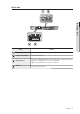
Back side M GENERAL FACTS Name Function USB Port This is a software uploading port of the System Keyboard. Composite Video IN/OUT This is an AV In / Out port. RS-485 (Port1, 2) For RS-485 communication, it will be connected to the RS-485 terminals of other System Keyboards or controlling devices such as cameras, and DVR. MYou can specify different protocols for Port 1 and Port 2.
installation INSTALLATION ENVIRONMENT SETUP The following information is prepared for safe installation of the unit. • This unit can be placed on a flat table or installed in the rack. It should not be used vertically or skew, but horizontally. • The location of the unit and the composition of wiring are very important in properly operating the system. When equipment is placed too close or if ventilation is not properly done, system may not work properly, and maintenance of the system may be difficult.
ADJUSTING SYSTEM KEYBOARD ANGLE You may adjust the angle of the product as shown below. M INSTALLATION FIXING POWER CORD Hang the power cord as shown in the following figure to prevent it from being deviated when you connect it with the main body.
connecting with other equipment You can use the SSC-5000 System Keyboard with a camera, DVR, and the other equipments. This chapter describes how to connect each equipment. CONNECTING RS-485 DEVICE - Connect RS-485 Device through the port in the back of SSC-5000. - You are able to install and control the camera and DVR supporting RS-485 communication. - Either Half Duplex or Full Duplex method is applicable for connection. M For the Half Duplex method, use TX +,-.
Connecting SHR-4081, SHR-4160, SHR-508X Series, SHR-516X Series, SHR-208X and SHR-216X Series DVRs Connect to SSC-5000 through the RS-485 port on the rear of the DVR. W Connecting as Half Duplex - Connect TX (+) of the RS-485 port of the DVR to TX (+) of SSC-5000. - Connect TX (-) of the RS-485 port of the DVR to TX (-) of SSC-5000. M CONNECTING WITH OTHER EQUIPMENT W Connecting as Full Duplex - Connect RX (+) of RS-485 port of the DVR to RX (+) of SSC-5000.
connecting with other equipment Connecting PC Based DVR - Connect SSC-5000 through the RS-485 port in the back of PC Based DVR. - Connect SIGNAL (+) in the RS-485 port of PC Based DVR with TX (+) of SSC-5000. - Connect SIGNAL (-) in the RS-485 port of PC Based DVR with TX (-) of SSC-5000. CONNECTING TO PC USING USB PORT You can use the provided USB cable to connect to the PC with uploading software for updating software of the System Keyboard.
BASIC SYSTEM DIAGRAM OF SSC-5000 1. One Keyboard to One Device Digital Video Recorder Digital Video Recorder Digital Video Recorder 3. Multiple Keyboards to Multiple Devices (“Daisy-Chain”Type Wiring) Digital Video Recorder Digital Video Recorder M Do not use together with the SSC-2000/SSC-1000 because it is different with the SSC-2000/SSC-1000 in communication method. In case of using the keyboard connected SSC-931T Version 1.4, make sure the address of connected keyboards differ from each other.
instructions LOG-IN 1. Turn on the power of all the components of the system. 2. When the power is applied by connecting the power adapter at the back of system keyboard, the following indication is displayed on the LCD screen. Login Operator No. Password Clear Enter 3. Using the keypad of the touch screen or the number key of the keyboard, enter the registered Operator number (1~32) and press . Login Error No. The default Operator No. is 1.
CAMERA CONTROL W Selecting a camera 1. Press “CAM” ( be as follows. ) key. The camera display part of the screen will 2. Enter the camera number (0~255) you want by using the number key and press [ENTER] button. CAM 002 MON 002 W Selecting a monitor 1. Press the [MON] button. 2. Enter the monitor number(0~255) that shows the image of the chosen camera and press . W PAN/TILT control Move the joystick of the keyboard to regulate PAN/TILT of the camera.
instructions W PRESET movement Press the [PRESET] button on the keyboard to start PRESET POSITION movement. The screen will appear as shown in the right figure. Preset CAM 000 MON Save 001 Delete PRESET position movement 1. Enter the preset number you want to operate. 2. Press [ENTER] button. PRESET programming This function is to set the camera screen the user wants to call and monitor whenever he/she wants to. Maximum 128 screens can be preset. (0~127) Preset CAM 000 MON Save 001 1.
Clear PRESET mode Press icon on the right below to go out of the PRESET mode. It will return to the camera control mode. Preset CAM 000 MON Save 001 Delete 1. You can title the selected camera. Press the camera title line to call the title input page on the screen. M INSTRUCTIONS W CAMERA TITLE input CAM 000 MON 001 2. English small letter input page will appear. CAM 000 MON 001 3. Press if you want to enter large letters.
instructions W CAMERA connection information Press the part marked as shown in the right figure to know the number of DVR that are connected to the selected camera. CAM 000 MON 001 A window will appear as shown in the right figure when you press the camera number display part. Connecting Info. CAM 000 MON 001 CAM DVR 000 001 Move to the connected device When you press on the connection information screen, DVR 001 will be selected and the screen will be changed into the DVR control mode.
DVR CONTROL Please refer to the manual of each DVR since DVR’s functions are varied depending on the model. Press the [MENU] button on the DVR set, then go to “System Remote Control Device” in the Settings menu to ensure that "Samsung System Keyboard" is properly set. The DVR will be controllable after the appropriate settings (ID, baud rate, etc.) are set. DVR selection CAM 2. Enter the DVR number (0~255) you want by using the number keys and press [ENTER] button. MON 3.
instructions 4. SHR-2XXX Series, SHR-508X, 516X Series DVR Record Mode DVR 012 Search Freeze 012 Alarm Zoom Audio Eject SHR-5082 MON 000 DVR Select Channel Select Channel SHR-5162 MON 000 DVR 002 002 SHR-5082 SHR-2042 MON MON 002 002 Select Channel Controlling the PTZ device connected to the DVR PTZ devices connected to some DVRs may not be controllable, depending on the DVR model.
DVR channel selection 1. Press the icon below on the DVR screen. 2. A channel selection screen will appear as shown in the right figure. DVR 011 SPR7416 MON 000 4 div. Search DVR 9 div. Record 011 16 div. Alarm Off Rotate Select Channel SPR7416 MON 000 3. Select the channel you want. M INSTRUCTIONS 4. Press the icon on the lower right to finish selecting and return to the DVR control screen. M DVR channel can be selected by using the number keys (0~9) of the keyboard.
MENU setup MAIN MENU 1. Press the [MENU] button of the keyboard and a log-in window will appear as follows. Login Operator No. 2. Using the number keys, enter the correct Operator No. and Password. Password 3. MAIN MENU will be displayed on the screen when you complete the log-in process. 4. Press the item you want to control on the main menu. Press the icon in the main menu to return to the camera control mode.
Protocol Port1/Port2 The protocol of the RS-485 communication can be set. RS-485 communication of the system keyboard supports Camera Protocol as follows. Keyboard Setup Choose one protocol among SAMSUNG / Pelco-D / Pelco-P / Vicon / Panasonic / Kalatel / Diamond / AD / Philips / Erna / VCL TP / Techwin / Honeywell. M The multimedia protocol provided by us may not be supported depending on the installation conditions.
MENU setup New Password 1. Enter the new password. 2. Enter the password by using the number keys (0~9) and press the [ENTER] button. M Maximum 6-digit figure can be entered. Confirm New Password This is to confirm the new password. Enter the password by using the number keys (0~9) and press the [ENTER] button. M If the entered number is not same as the New Password, an error message “Invalid Password!!” will be displayed on the screen. You have to start again from entering the operator no.
Confirm New Password This is to confirm the new password. Enter the password by using the number keys (0~9) and press the [ENTER] button. M If the entered number is not same as the New Password, an error message “Invalid Password!!” will be displayed on the screen. You have to start again from entering the operator's number. A window will appear as in the right figure when the confirm process is completed. Keyboard Setup RS-485 Communication Setup ¨ Operator No.
MENU setup A message will appear when downloading is completed. Keyboard Setup Camera Data Download Camera 000 Download Complete !! CAMERA DATA UPLOAD This function is to download the data set in SAMSUNG DOME CAMERA and upload them to a new camera. UPLOAD check screen If there is no camera data stored in the system keyboard Camera DATA uploading is not possible. Press , , icon to return to the Keyboard Setup screen. Keyboard Setup Camera Data Upload No Camera Data On your System.
SYSTEM INFORMATION AND SETUP S/W Version Displays the present version. It is not available to set. Keyboard Setup System Information and Setup S/W version v1.00_080531 ¨ Language English ¨ Load Factory Default ¨ Display Mode Normal Displays the present Set language. 1. Press the to change the language. Keyboard Setup 2. System keyboard supports English / Français / Deutsch / Español / Italiano/ ĬŏōōņńŅ / Polski/ 中國語 / 한국어 / Ă&4,: 5Ã3,±& / 日本語 / PORTUGUÊS / DUTCH / DANSK / HRVATSKI.
MENU setup OPERATOR LEVEL There are 3 levels of user, who can be registered as a user, including Admin. / Manager / Operator. Admin is the highest level. The range and limit to the usage of various setup menu and system function depends on the user's level. Admin.
others PRODUCT SPECIFICATION Item Description CONNECTOR TYPE : 8P TERMINAL TYPE M OTHERS INTERFACE(RS-485) PORT : 2 PORT BAUD RATE : 1200 / 2400 / 4800 / 9600 / 19200 / 38400 bps 4.3" TFT LCD PANEL + TOUCH PANEL EFFECTIVE DISPLAY AREA : 95.040mm[H] x 53.856mm[V] TFT LCD PANEL NUMBER OF DOTS : 1440[H] x 272[V] DOT PITCH : 66.0㎛[H] x 198.0㎛[V] USB PORT (USB 2.0) S/W Upgrade VIDEO INPUT/OUTPUT Composite Video 1.
others TROUBLESHOOTING (FAQ) PROBLEM SOLUTION • Check the RS-485 communication line. The system keyboard communication is not worked. • Check the address setup of system keyboard. • Refer to “RS-485 Communication Setup” of “Menu Setup” for the method of address setup. (see page 22) • Supply power to the system keyboard while you are pressing the [MENU] and [ENTER] buttons on the keyboard simultaneously. The password in the screen of system log in is lost. • Press buttons until the “Beep” sounds.
Correct Disposal of This Product (Waste Electrical & Electronic Equipment) (Applicable in the European Union and other European countries with separate collection systems) This marking shown on the product or its literature, indicates that it should not be disposed with other household wastes at the end of its working life.