DVD-VCR COMBINATION SV-DVD1E SERVICE MANUAL SERVICE Manual SV-DVD1E For mechanical disassembly and adjustment, refer to the “Mechanical Manual” (DX-9R DVD-VCR COMBINATION AC68-00001A). CONTENTS 1. Precautions ELECTRONICS 2. Product Specifications 3. Disassembly and Reassembly 4. Alignment and Adjustment 5. Troubleshooting 6. Exploded View and Parts List STANDBY/ON PHONES LEVEL OPEN/CLOSE DVD VCR COPY SELECT PROG REC EJECT 7. Electrical Parts List 8. Block Diagram 9. PCB Diagrams 10.
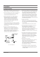
1. Precautions 1-1 Safety Precautions 1. Be sure that all of the built-in protective devices are replaced. Restore any missing protective shields. 2. When reinstalling the chassis and its assemblies, be sure to restore all pretective devices, including : control knobs and compartment covers. 3. Make sure that there are no cabinet openings through which people--particularly children -might insert fingers and contact dangerous voltages.
Precautions 11. Always connect a test instrument’s ground lead to the instrument chassis ground before connecting the positive lead; always remove the instrument’s ground lead last. 12. Observe the original lead dress, especially near the following areas : Antenna wiring, sharp edges, and especially the AC and high voltage power supplies. Always inspect for pinched, outof-place, or frayed wiring. Do not change the spacing between components and the printed circuit board. Check the AC power cord for damage.
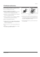
Precautions 1-2 Handling the optical pick-up The laser diode in the optical pick up may suffer electrostatic breakdown because of potential static electricity from clothing and your body. The following method is recommended. (1) Place a conductive sheet on the work bench (The black sheet used for wrapping repair parts.) (2) Place the set on the conductive sheet so that the chassis is grounded to the sheet. (3) Place your hands on the conductive sheet(This gives them the same ground as the sheet.
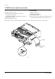
Precautions 1-3 DVD Deck disassembly and reassembly 1-3-1 Disassembly 1-3-2 Assembly 1) Remove the power cable. 2) Switch SW3 on Deck PCB to “OFF” before removing the Flat-Cable. ( Inserted into DVD Main PCB DCN1. See Fig. 1-3) 3) Disassemble the Deck. 4) Disassemble the Deck PCB. 1) Replace the Pick-up. 2) Assemble the Deck PCB. 3) Reassemble the Deck. 4) Insert Flat-Cable into DVD Main PCB DCN1 and switch SW3 on Deck PCB to “ON”.
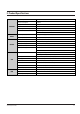
2. Product Specifications GENERAL Power Requirements AC 100-240V, 50/60Hz Power Consumption 32Watts Weight 5.6kg Dimensions W 430mm x D 357mm x H 100mm Operating ambirnt Temperature +5°C ~ +35°C Installation conditions Operation position : Horizontal, Ralative humidity : Below 75% INPUT OUTPUT Video input (Rear) RCA jack : 1.
Product Specifications MEMO 2-2 Samsung Electronics
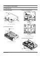
3. Disassembly and Reassembly 3-1 Cabinet and PCB 3-1-3 Ass’y Front Panel Removal 3-1-1 Cabinet Top Removal Œ REMOVE 1 SCREW ´ REMOVE 1 SCREW ˇ REMOVE 3 SCREWS Œ RELEASE 4 HOOKS (Top View) Fig. 3-1 Cabinet Top Removal 3-1-2 Bottom Cover Removal Œ REMOVE 7 SCREWS ´ RELEASE 3 HOOKS (Bottom View) Fig. 3-3 Ass’y Front Panel Removal 3-1-4 Function-Timer PCB Removal Fig. 3-2 Bottom Cover Removal Œ RELEASE 6 HOOKS Fig.
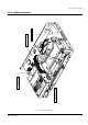
Disassembly and Reassembly 3-1-5 Chassis Removal Œ REMOVE 3 SCREWS ´ REMOVE 3 SCREWS DVD MAIN PCB DVD-DECK S.M.P.S. PCB ¨ REMOVE 1 SCREW ˇ DISCONNECTS CN02/CN03 ˆ REMOVE 2 SCREWS VCR MAIN PCB Ø REMOVE 1 SCREW Fig. 3-5 Chassis Removal 3-1-6 VCR Main PCB Removal Œ REMOVE 3 SCREWS When installing the ass'y full deck on the Main PCB, be sure to align the assembly point of mode switch. MODE SWITCH ASSEMBLY POINT Fig.
Disassembly and Reassembly VCR MAIN PCB FUNCTION-TIMER PCB S.M.P.S. PCB DVD MAIN PCB 3-2 Circuit Board Locations Fig.
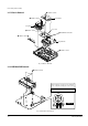
Disassembly and Reassembly 3-3 DVD Deck 3-3-1 PCB Deck Ass’y and Ass’y P/U Deck Removal 1) Remove the soldering of SLED+, SLED- Œ and TM+, TM- ´. 2) Disconnect CN3 ˇ, CN2 ¨. 3) Remove 1 Screw ˆ and lift up the PCB Deck Ø. 4) Remove 1 Screw ∏. 5) Push the Hook ” in the direction of arrow “A” and lift up the Ass’y P/U Deck ’ in direction of arrow “B”. ˆ 1 SCREW Œ SLED+/SLED´ TM+/TM¨ CN2 Ø DECK PCB ˇ CN3 ’ ASS'Y P/U DECK ∏ 1 SCREW "B" "A" ” HOOK Fig.
Disassembly and Reassembly 3-3-2 Tray Disc Removal 1) Insert a Screw Driver Œ into Emergency Hole ´ and push the Sider Housing ˇ in the direction arrow “A”. 2) When the Tray Disc ¨ comes out little, pull it in the direction arrow “B” by hand. 3) Pull the Tray Disc ¨ to disassemble , while simultaneously pushing 2 Stoppers ˆ (left, right) in the direction arrow “C”, “D”. ˆ STOPPER "C" "A" "D" ¨ TRAY DISC "B" ˇ SLIDER HOUSING ˆ STOPPER Œ SCREW DRIVER ´ EMERGENCY HOLE Fig.
Disassembly and Reassembly 3-3-3 Slider Housing Removal 1) Push the Slider Housing Œ in the direction arrow “A”. 2) Lift up the Slider Housing Œ. Œ SLIDER HOUSING "A" Assembly PUSH Fig.
Disassembly and Reassembly 3-3-4 Housing Ass’y Removal 1) Remove Belt Œ and 1 Screw ´. 2) Remove 1 Screw ˇ and lift up the Pulley Gear ¨. 3) Push the Hook ˆ in the direction arrow “A” and lift up Gear Tray Ø, Gear Housing ∏. 4) Push the 4 Hooks ” bottom side in the direction arrow “B” and lift up the Motor Load Ass’y ’. 5) Remove Clamper Ass’y ˝.
Disassembly and Reassembly 3-3-5 Sub Chassis Removal 1) Remove the 4 Screws Œ. 2) Lift up the Ass’y Brkt Deck ´. Œ 4 SCREWS ´ ASSY-BRAK DECK Fig.
Disassembly and Reassembly 3-3-5 Sub Chassis Removal 1) Remove the 4 Screws Œ. 2) Lift up the Ass’y Brkt Deck ´. Œ 4 SCREWS ´ ASSY-BRAK DECK Fig.
Disassembly and Reassembly 3-3-6 Ass’y Brkt Deck Removal 1) Remove Washer Œ. 2) Remove Gear Feed B ´ , Gear Feed A ˇ. 3) Remove 2 Screws ¨. 4) Remove Shaft Pick-Up ˆ and Pick-Up Assy Ø. 5) Remove 1 Screw ∏. 6) Remove 2 Screws ”. 7) Remove 3 Spring Spindle ’ and Motor Spindle Ass’y ˝. ˝ MOTOR SPINDLE Ø PICK-UP ASS'Y ˆ SHAFT PICK-UP ¨ 2 SCREW ’ SPRING SPINDLE Œ WASHER ´ GEAR FEED B ∏ 1 SCREW ” 2 SCREWS ˇ GEAR FEED A Fig.
Disassembly and Reassembly MEMO 3-10 Samsung Electronics
4. VCR Alignment and Adjustments 4-1 Reference 1) X-Point (Tracking center) adjustment, “Head switching adjustment” and “NVRAM option setting” can be adjusted with remote control. 2) When replacing the VCR Main PCB Micom (IC601) and NVRAM (IC605 ; EEPROM) be sure to adjust the “Head switching adjustment” and “NVRAM option setting”. 3) When replacing the cylinder ass’y, be sure to adjust the “X-Point” and “Head switching adjustment”. 4) How to adjustment.
Alignment and Adjustments 4-1-2 SW710 (TEST) location for adjustment mode setting TEST (SW710) BUTTON Fig.
Alignment and Adjustments 4-2 Mechanical Adjustment Note : Refer to the Mechanical Manual “DX-9R (AC68-00001A)” for the adjustment and confirmation of ass’y full deck. 4-2-1 The number and position of test point Test point : TP01-2 (Audio Output) TP01-3 (Envelope) TP01-4 (H’D S/W -Trigger) TP01-5 (Control Pulse) CONTROL PULSE HEAD SWITCHING ENVELOPE AUDIO OUTPUT Fig.
Alignment and Adjustments 4-3 Head Switching Point Adjustment 1) Playback the alignment tape. 2) Press the “SW710 (TEST)” button on Function-Timer PCB to set the adjustment mode. (See Fig. 4-2) 3) Press the “SPEED” button of remote control then adjustment is operated automatically. (See Fig. 4-1) 4-4 NVRAM Option Setting 1) NVRAM Option is adjusted at production line basically.
Samsung Electronics Check IC701, DT701. Yes Data IN, Out, CLK IC701-6, 5, 8. (F/TIMER PCB) Yes AL5V IC701-33, 45. (F/TIMER PCB) Yes 8MHz IC601-18, 19. (VCR MAIN PCB) Yes AL5.8V IC601-41, 69, 92. (VCR MAIN PCB) Yes AL5.8V CN1P2-Pin3. (SMPS PCB) Yes AL5.8V D31. (SMPS PCB) Yes Fuse F01 is OK? (SMPS PCB) No Power (Standby LED OFF) No No No No No No No Check CN701 Connector Wafer. Check XT602, IC601. Check D692, W200, W257. Check CN1P2 Cable. Check Trans PT01, D31 Change Fuse F01.
5-2 A YES SW 30Hz IC601-24 YES CYLINDER ROTATION HIGH (END SENSOR) IC601-74 YES TAPE LOADING OPERATION LOAD A TAPE AND PRESS PLAY BUTTON TURN VCR POWER ON MECHANISM DOESN'T OPERATE IN PLAY MODE NO NO LOW NO CHECK IC602 YES (LOAD) IC601-38:HIGH IC601-39:LOW CYL FG.PG IC601-96.97 SEE (CYLINDER DOES NOT ROTATE) CHECK TAPE (VCR Section) NO CHECK START/END SENSOR (S601/S602) IC601 CHANGE IC601 YES PROG.SW STATE IC601-76, 77, 78 PULSE (S.T REEL) IC601-98.
Samsung Electronics SEE (AUDIO MISSING IN RECORD MODE) YES REC-VIDEO YES D-REC A (H) IC601-1 FULL ERASE (H) IC601-68 NO NO SEE (VIDEO MISSING IN RECORD MODE) CHECK IC601 CHANGE SW602 YES YES SEE (PLAY MODE DOESN'T OPERATE) SAFETY TAB EJECT NO (VCR Section) REC MODE LOAD VCR WITH A BLANK TAPE AND PRESS RECORD BUTTON YES PLAY OPERATION RECORD MODE DOESN'T OPERATE NO CHANGE TAPE CHECK MECHANISM ROTATE CAPSTAN MOTOR ROTATION F.FWD MECHANISM STATE IC601-93.98.99 YES F.
5-4 CHECK MECHANISM YES DOES CAPSTAN MOTOR ROTATE? REW MECHANISM STATE IC601-93.98.99 YES REW INDICATOR IN THE DISPLAY PRESS REWIND BUTTON YES F.FWD OPERATION LOAD A TAPE REWIND DOESN'T OPERATE NO STOP NO NO CHECK IC601-25 (CM F/R) SEE (MECHANISM DOES NOT OPERATE IN PLAY MODE) CHECK TIMER YES PRESS REW KEY IN REMOTE CONTROL SEE (FAST FORWARD DOESN'T WORK) (VCR Section) NO CHECK IC601. XT602 CHECK IC601 YES NOISE BAR LOCKING YES IS CAPSTAN SPEED CHANGED? PRESS F.
Samsung Electronics NO CHECK IC601 YES NOISE BAR LOCKING NO FWD SEARCH NO YES CHECK CAPSTAN MOTOR YES (CONTROL PULSE) IC601-89 CHECK CAP F/R LINE LOW CAP F/R IC601-25 CHANGE DECK SEE (PLAY DOESN'T OPERATE) (VCR Section) (PLAY MODE) (SEARCH MODE) YES IS CAPSTAN SPEED CHANGED? PRESS REWIND BUTTON FOR REV. SEARCH PLAY OPERATION REV.
5-6 NO NO CHECK TM401, ANTTENNA IN CHECK IIC CLK, DATA LINE CHANGE IC801 YES IIC CLK, DATA IC801-63, 64 CHECK IC801-2 TO TM401-24 LINE YES VIDEO SIGNAL TM401-24 NO NO CHECK SV-DVD1E TO TV CONNECTION.
Samsung Electronics CHANGE IC301 NO VIDEO IC301-29 YES VIDEO IC301-20 YES VIDEO FM IC301-74 PLACE THE VCR PLAY MODE YES VIDEO EE MODE OPERATION VIDEO MISSING IN PLAY MODE YES NO NO NO CHECK Q303-E CHECK Q802 NO VIDEO IC801-12 YES H'D SW IC301-11 SEE PAGE 6-6 (VIDEO MISSING IN EE MODE) (VCR Section) YES NO NO VIDEO IC801-19 CHECK IC801 CHECK VIDEO HEAD CHECK IC601-24 CHECK VIDEO OUT LINE CHANGE IC301 YES COLOR IC301-71 YES COLOR IC301-72 YES (VIDEO IN) RECORD MODE COLOR
5-8 COLOR IC301-59. 61 YES FM-ENV IC301-74 COLOR MISSING IN PLAY MODE NO NO YES CHANGE IC301 YES COLOR IC301-71 YES CHECK XT3X1 YES SW 30Hz IC301-10 NO NO NO CHECK Q308, C330, C328 CHANGE XT3X1 CHECK IC601-29 NOTE: XT3X1 - Always (4.433619MHz) SEE PAGE 6-7 (VIDEO MISSING IN PLAY MODE) (VCR Section) NO CHANGE IC6P01 YES (STB, CLK, DATA) IC6P01-9, 10, 11 NO OSC IN IC6P01-6 YES 2fsc IN IC6P01-2 OSD PICTURE MISSING NO NO NO 2fsc : 8.
Samsung Electronics CHANGE IC6P01 YES IC6P01-9, 10, 11 (STB, CLK, DATA) YES IC601-72 "L" YES IC6P01-8 "L" (SYNC JUDGE) YES SELECT LINE MODE WITHOUT INPUT SIGNAL BLUE MISSING IN STOP MODE NO NO NO CHECK IC6E01 YES VIDEO SIGNAL IC6P01-24 CHECK IC601-8, 6, 7 CHECK IC6P01-8 TO IC601-72 (VCR Section) NO CHECK OSD VIDEO IN LINE CHECK DVD BLOCK NO CHANGE IC801 CHECK IC601-50 A MUTE LINE CHECK 9V LINE YES IC801-40, 52 AUDIO SIGNAL INPUT NO NO H NO DVD NO AUX YES IC801-28 YES LI
5-10 CHECK CYLINDER YES IC801-27, 32 AUDIO SIGNAL YES YES CHECK IC501 CHECK R504, CHANGE IC501 CHECK C861, C863, R510, R518 MONO IC501-22.
Samsung Electronics MONO CHECK R3A10, C3A04 AND IC301-100 AUDIO SIGNAL YES IC301-1 AUDIO SIGNAL CHANGE IC501 YES IC501-18 AUDIO FM(MIXED) HIFI AUDIO SELECT PLACE THE VCR IN PB MODE CHECK "AUDIO MISSING IN EE MODE" AUDIO MISSING IN PB MODE NO NO CHECK ACE HEAD C3A15, C3A16, R3A06, R3A07, R3A08 AND CHANGE IC301 CHECK IC501-35(A.H D SW) C514, C513, R503 AND CHANGE CYLINDER OR IC501 (VCR Section) CHANGE IC601 YES CHECK CTL PULSE AC LEVEL (SP.
5-12 CHECK CAPSTAN MOTOR YES CN604-4 2.7V YES CN604-3 2.7V PLACE THE VCR IN PLAY MODE YES CN604-8 AL 5V YES CN604-5 10V CAPSTAN DOES NOT ROTATE NO NO NO NO CHECK R685, R609, C623 YES CN601-10 OUTPUT(PWM) CHECK R660, C691 YES IC601-3 OUTPUT(PWM) CHECK 5.8V AT AL5.
Samsung Electronics C No focus incoming and no disc occurs. Yes LD is outputted from object lens at play key input? No Disc recognition No D (DVD Section) C Check open state from DRIC4 to pick-up. Yes SIC3-1, 2 output are normal? Yes FE in SIC1-25 is within specified range? No focus incoming No No Check SIC3 Check RIC1 and A, B, C, D input.
5-14 Check the Sled Motor and connection Yes LED+, SLEDSIC3-32, 33 output are normal? Yes SLD, SIC1-34 output is normal? No pick-up home positing No No (DVD Section) Check SIC3 Check MIC1 Yes RIC1-21 is 5V? LD out pick-up replace. Yes Current exceeds 0.1A? Yes Divide RQ1 emitter terminal voltage and 5V real voltage difference into 10ohm. D NO LD CD ON No No (DVD Section) Open check in related circuit.
Samsung Electronics See "Fine Seek Check" Yes TE occurs in search range? Yes Actual velocity occurs at SIC4-32, 33 terminal? Yes Actual velocity occurs at SIC1-34 terminal? Yes MIRR, SIC1-157 output is normal? No Search Operation No No No No Focus On? Check SIC3 peripheral circuit. Check SIC1 peripheral circuit. Check RIC1 peripheral circuit. Yes RFAGCO, RIC1-72 output level is normal? (DVD Section) No C Check pick-up. No Check SIC1 peripheral circuit.
5-16 No No No No Check SIC3 soldering and power. Check SIC1, MIC1. No Check RIC1 peripheral circuit and A, B, C, D. No Check RIC1 soldering and power. Check path to RIC1 and SIC1. Yes RIC1-70 output are normal? Yes RIC1-71 output is normal? (DVD Section) After resoldering SIC1. Check or replace disc motor.
Samsung Electronics Check AVJ1, JK801 Audio out peripheral soldering shot, IC801. Yes IC801-36 "L"? (VCR MAIN PCB) Yes AOP1-1, 7 output is normal? (VCR MAIN PCB) Yes Analog output of AIC1-20, 21, 22, 23 is normal? (VCR MAIN PCB) Yes Normal DATA 0 is input in AIC1-6? (VCR MAIN PCB) CD/VCD/DVD L/R output error (Mixed Audio output) No No No No Check ZIC1-125 (CD/VCD ; 16.9344MHz, DVD ; 18.432MHz) Check ZIC1-121 output. Check IC601-50 mute. Check AOP1 peripheral circuit.
5-18 ZIC1 peripheral soldering and short check. Yes Signals are output from SIC1-42, 44? Yes 27MHz clock is input in DIC1-14? Yes 'NO DISK' appears after pick-up moves up and down twice at power on? DVD play error No No No Replace SIC1. Check 27MHz oscillating part. Check DIC1, MIC1 peripheral short. (DVD Section) E Yes Y signal VIC2-12, 13 Yes DVD SETUP in OSD, Video output is S-Video. S-Video output error No No Check VIC2. Change the video output S-Video.
Samsung Electronics E No R, G, B CN1-10, 12, 14 No R, G, B VIC1-9, 10, 12-15 Yes JC801-16 "H" (EURO AV) Yes IC601-49 "L" R,G,B output error Yes Yes No No Yes IC601-2 "H" Check IC601. Check CN1 to VIC1 Check VIC1 to JC801. Check IC601-2 to JC801-16. (DVD Section) No Check IC601. E Check the JK801/RCA cable.
Troubleshooting MEMO 5-20 Samsung Electronics
6.
6-2 157 21 153 602 (S.M.P.S. PCB) 157 22 S601A 1 702 12 CN8A 155 12 13 101 603 (DVD MAIN PCB) S.N.A. : Service Not Available 701 (FUNCTION-TIMER PCB) CN3A1B 601 (VCR MAIN PCB) S602A LD601A CN602B 200 155 REC D EE SP OM ZO INDEX MARK SVHS 3D SOUND DVD MUTE VOLUME TRK- TV VIEW A.DUB SHUTTLE ATR 155 VCR LAST PR AU DIO FRAME/STEP TV/VCR PROG OPEN/CLOSE TRK+ 155 UT01 STANDBY/ON TITLE 2 BRACKET-FRAME (S.N.A.) VCR DECK (S.N.A.
Exploded View and Parts List Loc. No 1 2 12 13 21 22 100 101 153 155 157 200 601 602 603 701 702 CN3A1B CN602B CN8A LD601A S601A S602A UT01 Parts No.
6-4 K530 K490 K248 K250 S.N.A. K188 K182 K502 K110 K330 K350 K240 K140 K340 G530 G532 G546 B473 S.N.A. S.N.A. G420 B448 G450 S.N.A. G001 G510 G480 S.N.A. B452 B410 K546 S.N.A. G555 S.N.A.
Exploded View and Parts List Loc. No B410 B440 B444 B446 B448 B452 B473 G001 G420 G450 G480 G510 G520 G527 G530 G532 G546 G555 G680 K110 K140 K182 K188 K240 K248 K250 K330 K340 K350 K490 K502 K530 K546 Parts No.
6-6 K221 K225 K200 K222 S.N.A. S.N.A. B456 S.N.A. B462 (OPTIONAL) B458 B570 B560 G542 B500 B484 B238 S.N.A. S.N.A.
Exploded View and Parts List Loc. No B238 B456 B458 B462 B484 B488 B500 B560 B570 G542 K200 K221 K222 K225 Parts No. AC61-50660A AC66-20576A AC66-20574A AC60-10517A AC66-20580A AC66-30543A AC66-30542A AC31-12017A AC60-10514A AC66-60051A AC61-21012A AC66-20581A AC60-30306A AC66-30547A Samsung Electronics Description ; Specification Remark SLEEVE-TENSION;-,POM M90-44,-,-,ID3,-,-, GEAR-JOINT 1;-,POM SW-01,M1.0,Z22,-,PCD2 GEAR-JOINT 2;-,POM SW-01,M1.0,Z14,-,PCD1 SCREW-TAP TITE;-,PH,+,-,M2.
Exploded View and Parts List 6-4 DVD Mechanical Parts H107 H103 H102 H100 900 H108 905 H105 H104 H109 S.N.A. H110 H106 H220 H200 H203 900 901 H202 900 906 H202 S.N.A. H206 H207 H205 H204 H208 H210 904 903 S.N.A. 900 H240 H241 900 6-8 S.N.A.
Exploded View and Parts List Loc. No 900 901 903 904 905 906 H100 H102 H103 H104 H105 H106 H107 H108 H109 H110 H200 H202 H203 H204 H205 H206 H207 H208 H210 H220 H240 H241 Parts No.
Exploded View and Parts List MEMO 6-10 Samsung Electronics
7. Electrical Parts List Loc.
Electrical Parts List Loc.
Electrical Parts List Loc.
Electrical Parts List Loc.
Electrical Parts List Loc.
Electrical Parts List Loc.No VL4 VL5 VL6 VL7 VL8 VR10 VR11 VR22 VR23 VR24 VR6 VR7 VR8 VR9 ZD801 ZD802 Part No Description ; Specification 2701-000145 2701-000145 2701-000145 2701-000145 2701-000145 2001-000969 2001-000969 2001-000969 2001-000969 2007-001166 2007-001216 2007-001216 2007-001166 2007-001247 0403-000297 0403-001211 INDUCTOR-AXIAL;1uH,5%,2.4x3.4mm INDUCTOR-AXIAL;1uH,5%,2.4x3.4mm INDUCTOR-AXIAL;1uH,5%,2.4x3.4mm INDUCTOR-AXIAL;1uH,5%,2.4x3.4mm INDUCTOR-AXIAL;1uH,5%,2.4x3.
Electrical Parts List Loc.No R36 VA01 W10 W11 Part No 2001-000440 1405-001026 2001-001037 2001-001037 Description ; Specification R-CARBON;1OHM,5%,1/8W,AA,TP,1.8X3.2MM VARISTOR;470V,600A,9x7mm,TP R-CARBON(S);0.39OHM,5%,1/2W,AA,TP,2.4X6. R-CARBON(S);0.39OHM,5%,1/2W,AA,TP,2.4X6.
Electrical Parts List Loc.
Electrical Parts List Loc.
Electrical Parts List Loc.
8.
Block Diagram MEMO 8-2 Samsung Electronics
9. PCB Diagrams 9-1 S.M.P.S.
PCB Diagrams 9-1 S.M.P.S.
PCB Diagrams 9-2 VCR Main Samsung Electronics 9-3
PCB Diagrams 9-4 SOLDER SIDE COMPONENT SIDE 9-3 DVD Main Samsung Electronics
PCB Diagrams 9-4 Function-Timer 9-5 DVD Deck Samsung Electronics 9-5
PCB Diagrams MEMO 9-6 Samsung Electronics
10.
Wiring Diagram MEMO 10-2 Samsung Electronics
11. Schematic Diagrams ♦ Block Identification of Main PCB - - - - - - - - - - - - - - - - - - - - - - - - - - - - - - - 11-2 11-1 S.M.P.S.
Schematic Diagrams ♦ Block Identification of Main PCB VCR MAIN PCB DVD MAIN PCB 11-2 Samsung Electronics
Schematic Diagrams 11-1 S.M.P.S.
Schematic Diagrams 11-2 Power Drive 11-4 Samsung Electronics
Schematic Diagrams 11-3 Function-Timer Samsung Electronics 11-5
Schematic Diagrams 11-4 System Control/Servo 11-6 Samsung Electronics
Schematic Diagrams 11-5 A/V Samsung Electronics 11-7
Schematic Diagrams 11-6 TM-Blcok (FRANCE, SWITZERLAND Only) 11-8 Samsung Electronics
Schematic Diagrams 11-7 Digital Audio Samsung Electronics 11-9
Schematic Diagrams 11-8 Hi-Fi 11-10 Samsung Electronics
Schematic Diagrams 11-9 OSD Samsung Electronics 11-11
Schematic Diagrams 11-10 Input-Output 11-12 Samsung Electronics
Schematic Diagrams 11-11 A2/NICAM Samsung Electronics 11-13
Schematic Diagrams 11-12 SECAM (OPTION) 11-14 Samsung Electronics
Schematic Diagrams 11-13 DVD Main-Micom Samsung Electronics 11-15
Schematic Diagrams 11-14 Servo 11-16 Samsung Electronics
Schematic Diagrams 11-15 AV Decoder Samsung Electronics 11-17
Schematic Diagrams 11-16 DVD Deck 11-18 Samsung Electronics