Premium Security Digital Video Recorder SVR-1650E/1640A/950E User’s Manual Thank you for purchasing a Samsung Digital Video Recorder. Before attempting to connect or operate this product, please read these instructions carefully and save this manual for future use.
Introduction Thank you for purchasing the SVR-1650E/1640A/950E. This is a user manual for SVR-1650E/1640A/950E. Before product installation and operation, please become thoroughly familiar with this user manual and other manuals referenced by this manual. This user manual and the software and hardware described here are protected by the copyright law.
Table of Contents Introduction ............................................................ 1 Product warranty and limits of responsibility ........................................... 1 Chapter1. Safety Cautions .......................................... 5 Symbols displayed for each item ......................................................... 5 Chapter2. Summary .................................................. 8 2.1 Features .............................................................................
SVR-1650E/1640A/950EUser Manual 4.5.1 Time search .......................................................................... 38 4.5.2 Event search ......................................................................... 40 4.5.3 Log search............................................................................ 41 4.6 Recording file playback .............................................................41 4.6.1 Jog dial / shuttle ring............................................................... 42 4.
5.8.3 Relay................................................................................... 84 5.8.4 TEXT ................................................................................. 84 5.8.5 EVENT-PRESET .................................................................... 85 5.9 Communication setup .............................................................. 86 5.9.1 5.9.2 5.9.3 5.9.4 5.9.5 5.9.6 NETWORK .......................................................................... 86 RS-232.......
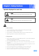
Chapter1. Safety Cautions Symbols displayed for each item Warning Refers to information users need to know in order to prevent serious injury or death. Caution Provides information users need to know in order to prevent minor injury or product damage. Before installation 9 Verify the supplied voltage (AC100V~AC240V) before connecting the power supply. 9 Make sure the power supply is off before installation. 9 Do not install in a very humid environment. Doing so may cause an electric shock or fire.
9 Do not apply excessive force when pulling on the power cord. Damaging the cord may cause an electric shock or fire. 9 Random replacement of built-in battery by other types of batteries may cause explosion. 9 The battery shall be replaced by the same battery. 9 The used batteries shall be disposed carefully because they can cause environment pollutions. Dismantling and cleaning 9 Do not dismantle, repair or modify the product deliberately.
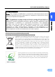
SVR-1650E/1640A/950EUser Manual FCC Compliance Statement Caution : Any changes or modification in construction of this device which are not expressly approved the party responsible for compliance could void the user’s authority to operate the equipment. 1 NOTE : This equipment has been tested and found to comply with the limits for a Class A digital device, pursuant to part 15 of the FCC Rules.
Chapter2. Summary This product is a digital video recorder that digitizes 16 channels of video input and stores it in the built-in hard disk drive. Product functions can be setup conveniently using the mouse and buttons on the front panel. Samsung SVR-1650E/1640E/1640A/950Eis a digital image recorder that can be used as security equipment in banks, apartments, and government and public offices. It is a stand-alone product with proven performance and stability.
SVR-1650E/1640A/950E User Manual Video recording High image quality MPEG4 video recording is possible. Up to 480 frames(SVR-1650E)/120 frames(SVR1640A/950E) per second of recorded video can be stored and pre-event recording can be done for up to 5 seconds before an event occurs. In addition, privacy is protected by the COVERT (image hiding) function.
Storage device A built-in hard disk drive is provided. User may also select to use DVD±RW, CD-RW and USB memory for backup. Standard storage: Built-in hard disk drive Various backup devices available: DVD±RW, DVD±R, CD-RW, CD-R and USB memory HDD Extension Unit (external extendable storage device) : SVS-5 (Sold separately as a designated device) Network Various networks including LAN, xDSL is supported.
SVR-1650E/1640A/950E User Manual 2.2 Components DVR package contains the main body and the following accessories. Please verify whether all accessories are included at the time of purchase. If any accessory is missing, inquire at the point of purchase. 2 2.3 Name and Function of Each Part 2.3.
Backup(Copy) section Category 1. DVD-Multi : DVR for backup Function Used to backup recorded/stored images on DVD/CD media. Jog/shuttle section Category 2. JOG/SHUTTLE Function Menu setup values can be adjusted and STEP function can be controlled with JOG. SHUTTLE can be used for moving items between menus, increasing or decreasing playback speed, changing playback direction and for controlling PTZ. Display section 3.
SVR-1650E/1640A/950E User Manual Function button section Category 11. ▲ 12. ▼ MENU 13. ◀ 14. ▶ 15. + 16. 17.COPY 18. SEARCH 19. MULTI 20. FUNCTION 21. PTZ 22. ENTER 23. ESC. Function Used for movement in the upper direction. Used for movement in the lower direction. Used for movement to the left Used for movement to the right Used to increase value to be setup or move to another page. Used to decrease value to be setup or move to another page. Display the copy menu.
2.3.2 Back connector terminals SVR-1650E/1640E/1640A SVR-950E 2 9 1 3 10 19 No. 2 3 4 5 6 7 8 9 10 I/O terminal names CH1~16 (SVR-950E: CH1~9) LOOP OUT RS-232C MONITOR A2 MONITOR A1 MONITOR B GROUND POWER IN SENSOR IN RELAY OUT 11 CONSOLE 12 RS-485/422 13 TERMINATION 14 USB 15 16 17 18 19 VGA OUTPUT ETHERNET(Main) AUDIO OUT AUDIO IN SATA1~4 1 14 11 12 14 15 4 16 17 5 6 7 8 18 13 Function BNC input connector terminal for the camera.
SVR-1650E/1640A/950E User Manual Refer to ‘Chapter 3. Installation method’ and ‘Chapter 4. Operation method’ for detailed description about setup and utilization. If you make a connection to ATM/POS or HDD Extension Unit, please refer to the manual. 2 2.3.3 Remote Controller Button names 1. MENU 2. STATUS 3. AUTO 4. D.ZOOM 5. SPOT 6. AUX 7. PTZ 8. COPY 9. PIP 10. RECORD( ) 11. SEARCH( ) 12. STOP( ) 13. STEP( ) 14. PLAY/PAUSE( ) 15. FAST( ) 16. DIR( ) 17. (▲) 18. (▼) 19. (◀) 20. (▶) 21. ENTER 22.
2.4 Product specification Video Items Input method Video input level Live screen presentation speed Live screen resolution Monitor output Specification Composite input 16 channels (SVR-1650E/1640A) / 9 channels(SVR-950E) 1.
SVR-1650E/1640A/950E User Manual Connector terminals Items Video input Loop output Monitor output SPOT Monitor output VGA output (PC monitor) Audio 25 pin DSUB(2) Dual RJ-45 9 pin DSUB USB port RJ-45 SATA output Specification BNC(SVR-1650E/1640A: 16, SVR-950E: 9) BNC(SVR-1650E/1640A: 16, SVR-950E: 9) BNC(2), RCA(Front 1) BNC(1) 15 pin VGA RCA input (4), RCA output (2 - including the front) Sensor input (SVR-1650E/1640A: 16, SVR-950E: 9), relay output(4) RS-422/485(2) RS-232C(1) Front (2), back (1) Network
Hard disk drive Items Max. no. of mounts Basic mount Hard disk drive type Min. speed Recommended product Specification 4 1 (built-in) EIDE(ULTRA DMA-133) 7200rpm Seagate series, Maxtor series, Samsung Electronics The recommended models are as follows. Manufacturer HDD capacity Buffer Interface Seagate 250G 8M PATA Seagate 500G 16M PATA Seagate 160G 2M PATA ※ If other products are used, HDD operation error may occur.
SVR-1650E/1640A/950E User Manual Copy Item Digital copy Specification DVD±RW, DVD±R , CD-RW, CD-R and External USB memory DVD±RW, DVD±R, CD-RW and CD-R media may be used.
Accessories Item Supplied accessories 20 Specification Network viewer program CD User manual Quick guide manual Remote controller Mouse (Not included in SVR-950E) Cable core RJ-45 cable (2 cable) Rack mount and screw D-Sub 25p Connector (2 ea) Power supply cable
Chapter3. Installation method 3.1 Overall connection 3.1.1 Front connection method Connection organization diagram for DVR front side terminals are as follows.
3.1.2 Back connection method The organization chart for DVR and monitors, CCTV cameras and external devices is as follows. Camera 1~16 Main Monitor SPOT SVR-950E SVR-1650E 1640E/1640A Warning LED Sensor Audio(Line Input) USB VGA Monitor ATM/POS SCC-3100A HDD Extension Unit Speaker LAN/WAN Speed Dome Camera PC SVR-1650E/1640E/1640A SVR-950E If you make a connection to ATM/POS, please refer to the manual.
SVR-1650E/1640A/950E User Manual 3.2 Detailed connection 3.2.1 Rack mount To mount the product, the enclosed rack must be mounted first. Mount sequence is as follows. The enclosed rack mount is mounted on the product. 3 SVR-1650/1640E/1640A SVR-950E The product is mounted on the 19 inch rack.
3.2.2 Video/Audio connection Main Monitor 1. Camera 2. Monitor Spot Monitor i VGA Monitor Speake Audio(Line input) 3. Voice SVR-1650/1640E/1640A SVR-950E 1. Camera Up to 16(SVR-950E: Up to 9) CCTV cameras can be connected to DVR. Connect the BNC terminal for each camera to the CAMERA IN terminal in the back of this product. If BNC terminal is only connected to CAMERA IN, a 75Ω terminating resistor is setup internally.
SVR-1650E/1640A/950E User Manual Image input from each camera is output simultaneously to the external device connected to the MONITOR OUT terminal in the back of the product. 2. Monitor To output screen information to the main monitor, connect the VGA terminal for monitor output in the back of the product and the monitor BNC terminal with a BNC cable. There are 5 monitor output terminals [BNC 3(SPOT 1), RCA 1, VGA 1) and up to 5 auxiliary monitors can be connected. 3 Monitor outputs are labeled A and B.
3.2.3 External connector MONITOR A1 MONITOR B CH1 CH2 CH4 CH3 CH5 CH6 CH7 2. Relay Out 1. Sensor In CH9 CH10 CH11 CH12 CH13 CH14 RS-422/485 SENSOR IN RELAY OUT CH8 TERM 1 TERM 2 1 2 3 4 1 2 3 4 CONSOLE USB3,4 CH15 RS-232C VGA 3. RS-422/485 SATA Output CH16 MONITOR A2 AUDIO IN 1 AUDIO IN 2 AUDIO IN 3 AUDIO IN 4 ETHERNET AUDIO OUT 6. LAN(Ethernet) 4. RS-232C 5.
SVR-1650E/1640A/950E User Manual 1. Sensor input (SENSOR IN) This is an external sensor connection terminal used to input information from the connected sensors or devices to the product. No. 1 2 3 4 5 6 7 8 9 10 11 12 13 S1 S2 S3 S4 S5 S6 S7 S8 S9 S10 S11 S12 S13 Description SENSOR 1 SENSOR 2 SENSOR 3 SENSOR 4 SENSOR 5 SENSOR 6 SENSOR 7 SENSOR 8 SENSOR 9 SENSOR 10 SENSOR 11 SENSOR 12 SENSOR 13 No.
2. Relay output (RELAY OUT) This is an alarm output terminal used to output alarms for sensor, motion detection, video loss and power OFF to external devices. No. 1 2 3 4 5 6 7 8 9 10 11 12 13 NO1 CM1 NC1 NO2 CM2 NC2 NO3 CM3 NC3 NO4 CM4 NC4 GND Description Normal Open Common Normal Close Normal Open Common Normal Close Normal Open Common Normal Close Normal Open Common Normal Close Ground No.
SVR-1650E/1640A/950E User Manual 3. External control equipment (RS-422/485) This is a terminal for connecting external control equipment. The switch labeled TERM is used to turn ON/OFF terminating resistance for RS–422/485 communication equipment. 3 PORT PORT A (Controller SCC-3100A Control) PORT B (Speed Dome Control) No.
PORT A : SCC-3100A terminal Controller Terminal ( PORT 1) RX+ RXTX+ TX- DVR PORT A RS-485 RS-422 1 or 8 8 2 or 7 7 1 2 ※ RS-422/485 connection can be selected from the SW1 switch. To connect RS-485: SW1 switch 1, 2 are turned ON.
SVR-1650E/1640A/950E User Manual PORT B : SPD-2200 terminal 3 Speed dome terminal D+ DGND DVR PORT B 9 or 16 10 or 15 13 ※ If GND is connected, a much sharper image quality can be seen. TERM2 switch 1, 2 must be set to ON.
SPD-2500 terminal Speed dome terminal D+ DGND DVR PORT B 9 or 16 10 or 15 13 ※ If GND is connected, a much sharper image quality can be seen. TERM2 switch 1, 2 must be set to ON. SPD-2300/3000/3300 terminal Speed dome terminal RXD+ RXDTXD+ TXDGND TX RX DVR PORT B RS-422 16 15 9 10 13 Terminal for RS-232 communication Terminal for RS-232 communication RS-485 9 or 16 10 or 15 ※ If GND is connected, a much sharper image quality can be seen. RS-422/485 connection can be selected from the TERM2 switch.
SVR-1650E/1640A/950E User Manual 4. Communication port (RS-232C) This is a port used to connect to the PC to control the product. No. 1 2 3 4 5 Description N/C(Not connected) RxD(Data receive) TxD(Data send) N/C(Not connected) GND(Ground) No. 6 7 8 9 Description N/C(Not connected) N/C(Not connected) N/C(Not connected) N/C(Not connected) 3 External devices ATM/POS may be connected and used. - SVR-1650E/1640A : RS-232C - SVR-950E : CONSOLE. 5.
Chapter4. Operation method 4.1 Preoperation inspection items Make sure you verify the input power source voltage before turning on the power. If product used for NTSC is used with a PAL device, it may malfunction initially(recognize as a NTSC device). In this case, if power is turned OFF and ON again, it will recognize the PAL device properly. 4.
SVR-1650E/1640A/950E User Manual 4.3.1 FUNCTION screen display If Channel 1~16(SVR-950E: Channel 1~9) is setup as screen mode and FUNCTION button is pressed, icons for FUNCTION-LIVE will be activated. FUNCTION icon can be used to setup SPOT, PTZ and PIP. 4 In the FUNCTION-PLAY screen, the following play screen will be displayed. 4.3.2 Single channel screen display If Channel 1~16(SVR-950E: Channel 1~9) button is pressed, each channel is displayed using the entire screen.
4.3.3 Multi screen display If MULTI button is pressed, 16 channels are displayed as a 16 DIVISION screen (For SVR-950E, channel 9 is partitioned into 9 segments on the screen.). If MULTI button is pressed once again, a 4 DIVISION screen is displayed. Each time MULTI button is pressed, a divided screen is displayed following the order for divided screen types setup in [Screen Setup]-[SEQUENCING].
SVR-1650E/1640A/950E User Manual 4.4 Recording 4.4.1 General recording If REC button is pressed, red LED is turned ON, N is displayed in the upper right corner and video recording is started. If REC is pressed again, video recording is stopped. 4 [RECORD-OFF] is set to ON in password function, password input is needed to stop REC. 4.4.
4.5 Search If SEARCH button is pressed, the following search menu is displayed. Video recorded items can be searched by time, by event and by date using the menu and played. Log file search is also possible. 4.5.1 Time search If [TIME] is selected after SEARCH button is pressed, images stored in the basic built-in HDD can be setup by ‘TIME’ or ‘CALENDAR’ and played. In case of ‘TIME’, date and time video recording was carried out is displayed.
SVR-1650E/1640A/950E User Manual In case of ‘TIME’, recorded images are viewed by selected time period. SVR-1650E/1640E/1640A 4 SVR-950E In case of ‘CALENDAR’, calendar helps to search recorded images conveniently through data and time table. After the date on the left calendar and the hour and channel on the right table are selected, minute can be selected. In the CALENDAR table, green section means event recording and Yellow section means normal recording.
4.5.2 Event search If [EVENT] is selected after SEARCH button is pressed, a screen for selecting the event to search for is displayed. User can search by event and play the result as needed. Channel : Select a channel for event search. 9 SVR-1650E/1640A : CH1~16 9 SVR-950E : CH1~9 Event type : Event type can be filtered for all events or [SENSOR/V-LOSS/MD/TEXT].
SVR-1650E/1640A/950E User Manual 4.5.3 Log search Log history can be searched to verify the time for video recording start and stop, power ON/OFF, system time change (CLOCK), menu setup change (SETUP). 4 [LOG] only provides a list and does not play recordings. Press the ESC button to exit the list. Select the modified Setup on [CONTENTS] and press ENTER button to verify authority and submenu information. 4.
4.6.1 Jog dial / shuttle ring Jog/Shuttl 9 Shuttle ring: Used to increase/decrease play speed and to change play direction, to move between menus 9 Jog dial: Used to search still images in paused state. 4.7 Live / Playback screen conversion If there is a video recording, press the PLAY/PAUSE button from the LIVE screen to get to the PLAY screen. Press the STOP button from the PLAY screen to return to the LIVE screen.
SVR-1650E/1640A/950E User Manual < Image freeze and copy function while LIVE or playback mode.> (USB memory stick is necessary.) Images can be paused and saved to USB memory stick while LIVE or playback mode. The still image is saved as bitmap (*.bmp) file. ▶ How to capture still image while LIVE mode. - Press [STEP] button to freeze images. (On the top of center, ‘Freeze’ is displayed.) - Though recording is operated, you can freeze and copy image without quit.
4.8 Digital zoom If FUNCTION button is pressed and digital zoom icon is clicked, zoom function can be used. 9 To move in the expanded screen, use the up/down/left/right buttons. 9 D-ZOOM button operates in the single screen mode for channel 1~16 (SVR-950E: channel 1~9). 9 To cancel, press the mouse right button or the ESC key. 4.9 Copy If COPY button is pressed, HDD content can be stored in other storage medium including DVD±RW/DVD±R/CD-RW/CD-R and USB memory stick.
SVR-1650E/1640A/950E User Manual After selecting a storage medium, select the channel for which COPY will be carried out and the image information [START-REC TIME /END-REC TIME]. Press ‘FORMAT’ to format media and then press ‘COPY’ to copy recorded images to the media from HDD. -If a recording is in progress, it is continued even during the time COPY is carried out. -Network backup and network playback function are not supported during the time COPY is carried out.
4.9.1 SLiM Player SLIM Player is a program that is automatically saved when making a backup copy of a movie file on a CD or USB using the copy function of the DVR. You may replay a backup copy of the data on a PC without installing a separate Player program on a PC. This function is only supported by DVR firmware version 1.8 or higher.
SVR-1650E/1640A/950E User Manual Button Name 7 Channel Info 8 9 10 11 12 13 14 15 16 Function Display the information of the channel that is saved. Display the information on the recording time for the file being Time Info played. Control of playback speed Adjust the playing speed.(1x/2x/4x/8x) These are functions related to ‘play’. - Move to the previous frame. Control of playback - Play in the reverse direction. functions - Temporary stop. - Play in the forward direction. - Move to the next frame.
4.10 PTZ From the selected LIVE entire screen SINGLE mode, press the PTZ button to adjust camera Pan, Tilt, Zoom or view the screen in preset (PTZ value for camera setup in advance) state. There are no PTZ related buttons on the remote controller. 4.10.1 PTZ adjustment 9 After pressing the PTZ button from the single screen, put the cursor on the P button and adjust using the shuttle.
SVR-1650E/1640A/950E User Manual 4.10.2 Preset setup 9 Select a desired channel from channel 1~16(SVR-950E: channel 1~9) in the LIVE screen and select the entire screen mode. 9 Press PTZ to select the PTZ mode (PTZ is displayed in the upper right corner of the screen.) 9 Press (PAN) / (TILT) / (ZOOM) and use the mouse and jog/shuttle to take the screen to the desired PTZ state. 9 Use PRESET located below PTZ and setup the value with the mouse (1~255). 1.
4.11 Quick setup Collection of frequently used menu items that can be used to modify setup values quickly. It can move to the [Quick Setup] screen by pressing the MENU button on the front of the product. 9 RECORDE MODE : Manual & Event or Schedul & Event setup item. 9 EVENT CHECK : Can be set to OFF, ALWAYS or TIMEZONE. 9 TIME SETUP : Setup the system time. 9 DATE FORMAT : Setup the date display format. 9 LANGUAGE : Language can be selected.
SVR-1650E/1640A/950E User Manual 4.12 PIP If FUNCTION button is pressed in entire screen mode, the FUNCTION screen is displayed. If the PIP icon is pressed from here, another screen can be viewed together. 4 SVR-1650E/1640A SVR-950E Live PIP from Live screen 1. Press the FUNCTION button and select the PIP icon. 2. From the menu on the right side of the live screen, select the desired channel. 3. If the desired channel is selected with the mouse, a small screen is displayed inside the screen. 4.
4.13 System information If FUNCTION button is pressed, the FUNCTION screen is displayed. If the STATUS from here, system related information is displayed as shown below. SVR-1650E icon is clicked SVR-1640A SVR-950E 9 TOTAL RECORDABLE TIME : The time duration that can be allocated to the entire portion of HDD for a given amount of image data received by the DVR in one minute.
SVR-1650E/1640A/950E User Manual 4.14 SPOT If FUNCTION button is pressed, the FUNCTION screen is displayed. If the SPOT icon is clicked from here, the following screen is displayed. If SPOT monitor is used, it can be used like the MULTI function for the main monitor.
Chapter5. Setup method 5.1 Menu organization Menu organization for DVR is as follows.
SVR-1650E/1640A/950EUser Manual Menu organization is as follows. Refer to‘5.5 ~ 5.10’ for details.
5.2 Initial value setup DVR product is shipped with the initial value setup listed below. If the initial values have been changed and the user wants to get back the initial values the product was shipped with, click [System Setup]-[System] in the menu and set [DEFAULT] to [Yes].
SVR-1650E/1640A/950EUser Manual Record setup Main menu RECORD PROGRAM Lower menu RECORD MODE PROGRAM PRE EVENT DURATION POST EVENT DURATION REPEAT RECORD MODE WARNING LEVEL AUDIO Initial value M&E PROGRAM K 3 sec 10 sec ON 5% OFF PROGRAM K IMAGE SIZE 704 x 240(NTSC) SVR-1650E : M=5, Q=H, E=10, Q=S SVR-1640A:M=1, Q=H, E=3, Q=S SVR-950E : M=2, Q=H, E=3, Q=S (Refer to ‘5.7.2 Record program’ for details.
Record program (SVR-1650E) NTSC Order SIZE PAL MANUAL QUALITY EVENT QUALITY SIZE MANUAL QUALITY EVENT QUALITY A 704 X 480 5 S 7 S 704 X 576 5 S 6 S B 704 X 480 3 S 4 S 704 X 576 3 S 5 S C 704 X 480 5 H 7 S 704 X 576 5 H 6 S D 704 X 480 3 H 4 H 704 X 576 3 H 5 H E 704 X 480 1 H 3 H 704 X 576 1 H 3 H F 704 X 240 10 S 15 S 704 X 288 10 S 15 S G 704 X 240 5 S 20 S 704 X 288 5 S 20 S H 704 X 240 3 S 10 S 704 X 288 3 S
SVR-1650E/1640A/950EUser Manual Record program (SVR-1640A) NTSC Order SIZE PAL MANUAL QUALITY EVENT QUALITY SIZE MANUAL QUALITY EVENT QUALITY A 704 X 480 1 H 5 S 704 X 576 1 H 5 S B 704 X 480 1 H 3 H 704 X 576 1 H 3 H C 704 X 480 1 H 1 H 704 X 576 1 H 1 H D 704 X 240 3 S 9 S 704 X 288 3 S 4 S E 704 X 240 3 H 5 S 704 X 288 3 H 3 S F 704 X 240 3 H 3 H 704 X 288 3 H 3 H G 704 X 240 1 H 3 S 704 X 288 1 H 3 S H 704 X 240 3
Record program (SVR-950E) NTSC Order SIZE PAL MANUAL QUALITY EVENT QUALITY SIZE MANUAL QUALITY EVENT QUALITY A 704 X 480 2 H 5 S 704 X 576 2 H 5 S B 704 X 480 1 H 3 H 704 X 576 1 H 3 H C 704 X 480 1 H 2 H 704 X 576 1 H 2 H D 704 X 240 5 S 9 S 704 X 288 5 S 5 S E 704 X 240 3 H 5 S 704 X 288 3 H 5 S F 704 X 240 3 H 3 H 704 X 288 3 H 3 H G 704 X 240 1 H 3 S 704 X 288 1 H 3 S H 704 X 240 5 M 9 S 704 X 288 5 M 5 S I
SVR-1650E/1640A/950EUser Manual Event setup Main menu EVENT MD RELAY TEXT EVENTPRESET Lower menu CHECK MESSAGE BUZZER SWITCH TO EVENT SCREEN EVENT DISPLAY MIN TIME EVENT DISPLAY MAX TIME TEXT MONITORING SENSOR TYPE - CH1~16(SVR-1650E/1640A) - CH1~9(SVR-950E) MD CHANNEL ALL AREA SET SENSOR, MD, V-LOSS,POWER SYNC CHANNEL DEVICE CHECK PROTOCOL LINES SENSOR PRESET MD PRESET Initial value OFF ON OFF OFF 3 sec 5 sec OFF NO CH1~16 (SVR-1650E/1640A)/ CH1~9(SVR-950E), ALL OFF CH1 NORMAL OFF 1 CH1/PRESET 0 CH1/P
Communication Main menu NETWORK RS232 RS422/ 485 E-MAIL DDNS 62 Lower menu TYPE DHCP IP ADDRESS SUBNET MASK GATEWAY DNS PORT SWR BAUD RATE DATA BIT PARITY BIT STOP BIT SYSTEM ID PORT TYPE BAUD RATE DATA BIT PARITY BIT STOP BIT E-MAIL CHECK TO SMTP SERVER AUTHENTICATION ID, PW SWR DDNS SERVER ID PW Initial value Ethernet OFF 000.000.000.000 255.255.255.000 000.000.000.000 000.000.000.
SVR-1650E/1640A/950EUser Manual System setup Main menu SYSTEM Lower menu LANGUAGE KEY BUZZER DEFAULT LOAD/SAVE CONFIGURATION FIRMWARE DOWNLOAD REMOTE SETUP DVR ALIAS REMOTE ID Initial value ENGLISH ON LOAD ENABLE - REMOTE LIVE MODE (Function exclusively for SVR-1650E/1640A) CH 1 ~ 16 (NTSC) CH 1 ~ 16 (PAL) HDD PASSWORD DATE-SETUP PTZ INTERNAL HDD HDD Format HDD EXTERNAL HDD HDD Format HDD USER AUTHORIZATION USER PASSWORD BUZZER IF CHECKING FAILS TIME SETUP DATE FORMAT DAYLIGHT SAVING NTP CHECK NTP
Copy Main menu Lower menu COPY STATUS Initial value 1.NONE(GSA-H55N) 2.NONE 3.NONE 4.
SVR-1650E/1640A/950EUser Manual 5.3 Operation description DVR can be setup easily using the USB mouse. Operation using the mouse Mouse Wheel Left Button Right Button 9 Left button : It is used to select menu or check the setting value. Used to selelet menu, verify setup values and cancel the popup menu.of main menu. 9 Right button : Used to Function or cancel popup menu. 9 Mouse wheel : Used to change setup values and display popup menu.
5.4 FUNCTION menu 5.4.1 LIVE/PLAY mode For SINGLE mode setup in the LIVE screen, all LIVE functions are activated and displayed. For MULTI mode setup in the LIVE screen, D-ZOOM, PIP, PTZ are inactivated and cannot be setup. MENU STATUS SPOT MULTI AUTO D-ZOOM PIP PTZ STEP PLAY/ STOP PAUSE FAST DIR If PLAY/PAUSE button is pressed, conversion to the PLAY screen occurs.
SVR-1650E/1640A/950EUser Manual STATUS If STATUS button is clicked, information related to the system is displayed. 9 SYSTEM INFORMATION 1 : Displays video recording program status information. 9 SYSTEM INFORMATION 2 : Displays VERSION, IP ADDRESS, MAC ADDRESS and AUDIO information.
SVR-1650E/1640E/1640A SVR-950E SPOT If SPOT button is clicked, the SPOT setup screen is displayed. SPOT monitor can be used to view SINGLE or divided screen. DISPLAY If MULTI button is clicked, the MULTI setup screen is displayed. Main monitor can be used for live observation in SINGLE screen or divided screen.
SVR-1650E/1640A/950EUser Manual AUTO If AUTO button is pressed, each channel and 4 DIVISION screen, 9 DIVISION screen and 16 DIVISION screen(SVR-950E: 4 DIVISION screen, 9 DIVISION screen) are automatically converted and displayed in time interval which was setup in [Screen Setup]–[SEQUENCING] in the conversion menu. In automatic screen conversion state, input from other buttons is not recognized. Push the AUTO button and cancel the Automatic screen conversion function before using other function buttons.
5.5 Menu screen description Organization of the menu screen is as follows. Main menu Sub menu Setup items Usage method Description of all menu screen setup value selection and modification is based on the assumption that the mouse is used. 70 9 Main menu : Main menu corresponding to each tab can be selected. 9 Sub menu : Lower menu that can be setup from the main menu can be selected. 9 Setup items : Setup items for the lower menu can be modified.
SVR-1650E/1640A/950EUser Manual 5.6 Screen setup If [Screen Setup] tab is clicked, lower menu related to [Screen Setup] is displayed as shown below. In screen setup, [SCREEN], [SEQUENCING], [DISPLAY], [COVERT], [SPOT] related setup values may be modified. 5 5.6.1 Screen Select a channel among the 16 available(SVR-950E: select a channel among the 9 available) and setup the channel name, brightness and contrast for that channel. Each channel can be setup separately like this.
VIDEO OUTPUT SELECT 9 Enhanced COMPOSITE: May be selected when current mode is 'Enhanced VGA'. Both COMPOSITE output and VGA output is possible and values from -9 to 9 may be setup for ‘CONTRAST'. In 'Enhanced COMPOSITE', image quality for VGA output may degrade slightly. 9 Enhanced VGA : May be selected when current mode is 'Enhanced COMPOSITE'. Only VGA output is possible and values from -7 to 7 may be setup for ‘CONTRAST’.
SVR-1650E/1640A/950EUser Manual 9 DWELL TIME : Setup the conversion display duration. Setup range is SKIP, 1~99 sec. 5 SVR-1650E/1640A SVR-950E 9 ORDER : Setup whole channels that will be converted. 9 User defined screen - 4DIV C : SVR-950E 4DIV E : SVR-1650E/1640A It sets the user defined screen with 4-partitioned segments for 4 channels. - 9DIV B : It sets the user defined screen with 9-partitioned segments for 9 channels. (This function is not supported by a SVR-950E series.
VIDEO LOSS SKIP [ON/OFF] : If setup as[ON], channels without image signals will be skipped automatically and only channels with image signals will be displayed in the screen.
SVR-1650E/1640A/950EUser Manual 5.6.3 Display Information to be displayed on the live screen can be selected. 9 DATE & TIME [ON/OFF] : If setup as [ON], current time is displayed in the live screen. 9 HDD FREE SPACE [ON/OFF] : If setup as [ON], remaining capacity for the mounted hard disk drive is displayed. 9 RECORD STATUS [ON/OFF] : If setup as [ON], video recording status display([NNNN]) is displayed in the upper right area of the screen during video recording.
5.6.4 Covert One channel among the 16 available(SVR-950E: among the 9channel) may be selected to setup the image hiding function. 9 LIVE COVERT : If image hiding is turned ON, image is not shown for live screen as in VLOSS and privacy can be protected. 9 PLAYBACK COVERT : If Playback Covert is turned ON, recorded images stored in HDD cannot be played back. 5.6.5 SPOT Setup items for the SPOT monitor. 76 9 TITLE DISPLAY : Determines if title is to be displayed in the SPOT monitor.
SVR-1650E/1640A/950EUser Manual 5.7 Record setup If the mouse is moved over the [Record Setup] tab, a video recording related lower menu is displayed as shown below. If ‘ENTER’ key, located in the front of DVR, is pressed or if lower level menu is selected with the mouse, detailed items may be viewed. 5.7.1 Record mode 5 Record mode setups manual and scheduled recording mode. 9 M & E : Manual setup. If REC button is pressed, video recording is carried out.
9 WARNING LEVEL : If available space in the hard disk drive reaches the setup percentage, a warning message will be displayed to the user. Possible setup range is 1 ∼ 10% and 5∼10% is generally used. 9 AUDIO : Select whether to store voice information. Scheduled video recording mode can be used to setup the date and time when video recording will be carried out automatically. Setting Method 9 As you set INDEX, DAY, PROGRAM and HOUR, then the content will be immediately displayed in the table.
SVR-1650E/1640A/950EUser Manual 5.7.2 Record program SVR-1650E SVR-1640A 9 In the SVR-1650E series, it is possible to assign a different resolution to each group. 9 Each group is comprised of the four channels as follows. Group1: Channel1~4, Group2: Channel5~8, Group3: Channel9~12, Group4: Channel13~16 5 SVR-950E [PROGRAM] can be used to adjust the FRAME RATE, QUALITY and RESOLUTION to setup video recording for M&E and S&E.
5.7.
SVR-1650E/1640A/950EUser Manual PAL (Installed Hard disk : 250G) SVR-1650E 704 x 480 100 50 25 16 8 4 1 2 4 6 12 25 SUPER Day 5 Hour Day 0 Hour Day 0 Hour Day 6 Hour Day 12 Hour Day 1 Hour 1 2 5 8 17 34 HIGH Day Day Day Day Day Day Hour Hour Hour Hour Hour Hour 2 4 8 13 27 55 MID Day Day Day Day Day Day 10 9 19 18 13 2 Hour Hour Hour Hour Hour Hour 7 13 27 43 86 172 LOW Day Day Day Day Day Day 20 18 13 1 2 4 Hour Hour Hour Hour Hour Hour 704 x 240 200 100 50 32 16 8 4 1 2 3 5 11 22 45 SUPER
5.8 Event setup For event video recording, a lower menu like the one shown below can be setup. If ‘ENTER’ key, located in the front of DVR, is pressed or if lower level menu is selected with the mouse, detailed items may be viewed. 5.8.1 Event 9 CHECK : Setup whether to check and store events. [Application time setup] will be activated only if [Event application time] is setup as [Time application ]. 9 MESSAGE [ON/OFF] : Select whether to display event items on screen with text.
SVR-1650E/1640A/950EUser Manual 5.8.2 Motion detection Analyze the image input by the camera to detect motion. If any change is detected, it is counted as an event. 9 MD CHANNER : Setup the channel for which motion detection will be carried out. 9 MD SETUP : Setup whether to detect motion for channel that will be used for motion detection. 9 AREA SETUP : Setup motion detection for each channel and specify the sensitivity and area with the mouse.
5.8.3 Relay When an event occurs, you can generate RELAY during sensor, movement detection, lost images, power alarm and record off using the output device connected to the RELAY OUT terminal on the back side of the product. Blinking green box indicates the state before selection. After selection, it turns yellow. 5.8.4 TEXT This setup allows material input with equipment like a POS System to be viewed with DVR equipment.
SVR-1650E/1640A/950EUser Manual 5.8.5 EVENT-PRESET This function allows each Speed Dome Camera wired to the DVR for quick setup of event detection and positioning to the initial location allocated per each event such as sensor input or motion detection. 9 SENSOR PRESET: Determine a preset number of each specific event sensor. When the preset sensor detects input signal, determine a PRESET number of each channel to command PRESET MOVE.
5.9 Communication setup Setup items needed to connect a computer to a network. Communication setup screen is as shown below. If ‘ENTER’ key, located in the front of DVR, is pressed or if lower level menu is selected with the mouse, detailed items may be viewed. 5.9.1 NETWORK 9 9 DHCP [ON/OFF]: DVR is automatically granted IP by DHCP server, it activates DHCP function. ‘DHCP’ is used in LAN environment where DHCP server operates.
SVR-1650E/1640A/950EUser Manual 9 SUBNET MASK : Input the [SUBNET MASK] address obtained from the internet service company of the user. 9 GATEWAY : Input the [GATEWAY] address obtained from the internet service company of the user. 9 DNS : Input the [DNS] address obtained from the internet service company of the user. 9 PORT : [PORT] assigned when connecting to a computer can be changed. If port is changed in the DVR, When the network setup is changed, it takes time to setup the network module again.
If using network by connecting the DVR body with IP router, you should designate a port for DVR from the Setup Menu of the IP router. The main body of SVR-1650E/1640A/950Euses 2 ports for TCP communication. In addition, it uses DHCP function supported by IP router. Even if dynamically allocating IP address to the main body of DVR for use, you should designate a port for IP, which DVR receives from the Setup Menu of IP router.
SVR-1650E/1640A/950EUser Manual 5.9.3 RS-422/485 Setup items needed to connect the product with surveillance equipment like camera and CCTV. 9 SYSTEM ID : Setup ID for DVR main body when connecting the product with equipment like a controller. 9 PORT TYPE: Setup type of port to use. 5 -PORT A: Connect the SCC-3100A controller. -PORT B: Connect the speed dome. -Control method -Controller : Connect PORT A and controller with RS422/485. Setup the SYSTEM ID corresponding to the connected SCC-3100A.
5.9.4 E-MAIL The manager can verify details related to the generated event through the email. 90 9 E-MAIL CHECK : If turned [ON], E-MAIL notice function is activated. 9 to 9 SMTP SERVER : This is a standard protocal for transmitting e-mail and used to prevent e-mail from spam mail. You must have a User ID for using e-mail. Ex) SMTP SERVER : kornet.net 9 AUTHENTICATION: Used during user account registration. .… : Setup the E-MAIL address to receive a transmission if an event occurs. ..
SVR-1650E/1640A/950EUser Manual 5.9.5 DDNS Configuration 9 SWR : Decide the use of SWR function. The SWR provides same function as below (DDNS), but this mode doesn't support connection by using ID. 9 DDNS : Decide the use of DDNS function. The DDNS function supports to connect web-server directly regardless of change of IP. 9 SERVER : Enter the DDNS server address. Ex) SMTP SERVER : kornet.net 9 Enter the ID & Password used to register product at iPOLIS website.
5.9.6 DDNS Registration DDNS Registration Procedure Step1) Sign up at iPOLiS website The website : www.samsungipolis.com Figure5-1. iPOLiS Hompage Figure5-2.
SVR-1650E/1640A/950EUser Manual Figure5-3. SIGN UP page: check ID availability 5 Step2) The product registration is possible after sign up. Figure5-4. Sign in at iPOLiS website Figure5-5.
Figure5-6. Product Registration (Check ID availability) Figure5-7.
SVR-1650E/1640A/950EUser Manual Step3) Configuration DDNS at DVR Select [Network] > [DDNS] on OSD Menu. 9 DDNS > ‘ON’ 9 SERVER > Enter the DDNS server address(Default:www.samsungipolis.com) 9 ID & PW > Enter the ID(Domain) & Password using the product registration at iPOLiS website. 5 The DDNS configuration is completed. Step4) The connection status of selected product can check on product list.
5.10 System setup System setup screen is as shown below. If ‘ENTER’ key, located in the front of DVR, is pressed or if lower level menu is selected with the mouse, detailed items may be viewed. 5.10.1 System 96 9 LANGUAGE : Select a language for the menu screen. 9 KEY BUZZER [ON/OFF] : Select whether to generate sound for key strokes when using the remote controller or when manipulating keys. 9 DEFAULT : Use to get back the initial setup values the product was shipped with.
SVR-1650E/1640A/950EUser Manual LOAD/SAVE CONFIGURATION 9 LOAD: Call the setup file stored in the USB Memory Stick and change the DVR setup value. 9 SAVE: Store the DVR setup value in the USB Memory Stick This function is not compatible between SVR-1650E, SVR-1640A and SVR950E. It may not be compatible with other firmware versions. Firmware version may be verified by pressing the "FUNC" button in front of the DVR. USB Memory Stick formatted in FAT32 format may not work.
9 REMOTE LIVE MODE Determines the frame and video quality of each channel of the network board. There are single mode and quad mode. When single mode is selected, a window for setting the framerate and bitrate that is sent to the network for each channel can be displayed. In auto mode, the network transmit data is regularly monitored and when the amount that is transferred drops, it automatically reduces the bitrate to compute the optimal transmission conditions.
SVR-1650E/1640A/950EUser Manual 5.10.2 HDD ‘HDD’ setups information for the mounted hard disk drive. Basic information related to HDD is displayed on the screen. Information for up to 4 hard disk drives can be viewed. 9 INTERNAL HDD : You may view the information on the HDD included in the DVR. 9 HDD FORMAT : Select whether to format the built-in, fixed HDD. If ‘YES' is clicked in the confirmation dialog window, formatting is carried out. 9 HDD : Setup can be for HDD1~HDD4 or ALL.
5.10.3 Password Setup password for user and manager to give authorization needed to use the product and to modify the setup. If ‘ENTER’ key, located in the front of DVR, is pressed or if lower level menu is selected with the mouse, detailed items may be viewed. One ‘ADMIN’ and 10 ‘USER’ are supported. (10 users are displayed as ‘USER1’~’USER10’) 9 USER AUTHORIZATION: Setup all user’s password and authority.
SVR-1650E/1640A/950EUser Manual System user authorization – ADMIN: All system setup is allowed. – USER1~USER10: Only allowed by authority. Factory default password ADMIN 11111111 USER1 22222222 USER2 33333333 USER3 44444444 USER4 55555555 USER5 66666666 USER6 77777777 USER7 88888888 USER8 99999999 USER9 12344321 USER10 43211234 - Modified password should be saved on MENU to affect after rebooting. Previous ADMIN’s and USER1’s password is kept after firmware upgrade.
5.10.4 Date setup It is used to setup date and time for the product. When setup is completed and stored, it is displayed on the live screen. 9 TIME SETUP : Setup the date, time and deffernce from GMT. From the dialog box shown above, use the mouse wheel or the buttons on the front of the product to modify the setup value. Then select [SET] to make the assignment. 9 DATE FORMAT : Setup format to use for date notation. Select from [year/month/day], [month/day/year], [day/month/year].
SVR-1650E/1640A/950EUser Manual 5.10.5 PTZ If dome camera has been installed, camera ID can be assigned and setup for each channel to use the PAN, TILT, ZOOM functions. 9 CH NUMBER : For camera connected to each channel, assign an ID and setup the camera model. 9 CAMERA ID : User can assign an ID between 0 ~ 255 for each camera. 9 MODEL[None/SPD/PELCO(D) /PANASONIC/SCC/SRX/BOSCH] : Select the manufacturer for the connected camera. Signal input from a camera is different for each manufacturer.
5.11 Video recording search For video recording search, time, event and log file retrieval functions are provided. If ‘ENTER’ key, located in the front of DVR, is pressed or if lower level menu is selected with the mouse, detailed items may be viewed. The above is same as ‘4.5. Search’ after [SEARCH] button is pressed on DVR. 5.11.1 Time search From HDD, recorded images can be searched by using TIME of CALENDAR.
SVR-1650E/1640A/950EUser Manual In the CALENDAR table, green section means event recording and Yellow section means normal recording. 5.11.2 Event search Retrieval by event types including loss video, sensor and motion detection is possible. 5 Items selected during event search can be played back. If ESC key is pressed during playback, returns to the event search window.
5.11.3 Log search Log history for generated events can be verified. When the setup is modified, you can verify submenu information and authority by press [ENTER] button. < LOG file copy function> (USB memory stick is necessary.) Log file is recorded by DVR can be saved to USB memory stick. ▶ How to capture log file. - Press [MENU] button to main menu. (Or press [SEARCH] button.) - Select submenu ‘LOG’ after menu ‘SEARCH’. - Connect USB memory stick to DVR and press [COPY] button.
SVR-1650E/1640A/950EUser Manual 5.12 Copy If a storage medium is connected, video recorded images may be copied to the storage devices. If ‘ENTER’ key, located in the front of DVR, is pressed or if lower level menu is selected with the mouse, detailed items may be viewed. If USB and DVD±RW/DVD±R/CD-RW/CD-R storage is inserted, a screen like the one shown below is displayed. 9 STATUS : Progress status for the current copy operation is displayed. Please use recommended media.
5.13 Exit Modified setup values are applied when they are verified after the Save button is pressed. 9 108 As shown in the screen below, when setup has been modified and [SAVE] is pressed, the setup functions are applied. The setup functions can be cancelled by pressing “Do NOT SAVE”.
Chapter6. Trobleshooting DVR is an intricate mechanical device and it can malfunction. For such cases, take the following measures. Product is not turned ON when stand-by switch is pressed. Verify if the power supply cable is connected properly. Screen is not displayed when product is turned ON. Verify if video output terminal is properly connected to the CCTV monitor. Verify if the camera is properly connected to the input terminal. Verify if CCTV monitor brightness is appropriate.
If the power cable connector has been damaged If rain or water has entered the product If a liquid has been spilled on the product or if a foreign substance has entered the product If the product does not operate as described in this manual If the product has been seriously damaged after being dropped If there is a clear difference in performance 110
Product Specifications Model Power Source SVR-1650E Max.
Model SVR-1650E PAL SVR-1640A Power Source AC 100V~240V,(50/60Hz), Max. 2A Power Consumption Max.
Dimensions
SALES NETWORK SAMSUNG TECHWIN CO., LTD. 145-3, Sangdaewon-dong, Jungwon-gu Seongnam-si Gyeonggi-do 462-120, Korea Tel: +82-31-740-8151~8 Fax: +82-31-740-8145 SAMSUNG OPTO-ELECTRONICS UK, LTD. Samsung House, 1000 Hillswood Drive, Hillswood Business Park Chertsey, Surrey KT16 OPS Tel: +44-1932-45-5308 Fax: +44-1932-45-5325 P/No. : Z6806.0759.