
Installation Manual


INS_TE(C,U)-FX 08/12/19 PAGE 8
INSTALLATION AND OPERATION MANUAL TE(C,U)-F SERIES
INSTALLATION INSTRUCTIONS
1 - SET 10/100 SWITCH
Locate the 10/100 data rate DIP switch on the unit.
Set the data rate according to bandwidth required.
NOTE: The data rate must be set the same on both the local and remote units.
2 - SET WIRE PAIR DIP SWITCHES (UTP MODELS ONLY, FOR COAX MODELS SKIP TO STEP 3)
Locate the wire pair DIP switch on the unit.
Set the pair according to number of twisted wire pairs used (1 or 4).
NOTE: The number of pairs selected must be set the same on both the local and remote units.
PoE Pass-Through mode is only available in 4-pair mode and requires a PD device connected to
the remote unit to operate.
3 - SET LOCAL/REMOTE SWITCHES (1 AND 4 CHANNEL UNITS ONLY, FOR RACK UNITS SKIP TO STEP 4)
Locate the Local/Remote Dip switch and set to “LC” at the head end or “RM” at the camera end.
Locate the Local/Remote push button switch (coax units only), and set to the same setting as the dip switch.
The TE(C,U)-F16 units are preconfigured as Local devices.
4 - CONNECT EXTENDED WIRING
Connect Extended Distance Port to field wiring.
5 - CONNECT NETWORK WIRING
Using CAT5/5e cabling, connect Local unit to network and Remote unit to camera.
6 - CONNECT POWER
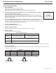
Connect power to unit per the following table:
Power Connections per Use Case
Unit Local Power Pass-Through PoE
TE(C,U)-F01 9 to 36 VDC or 18 to 32 VAC No external power required
TE(C,U)-F04
9 to 15 VDC (9 VDC
†
when in a SBP-C03 or SBP-C14 rack)
TE(C,U)-F16 9 to 15 VDC
†
Contact pre-sales support, or refer to the appropriate installation and operation manual when configuring and specifying power for a deployment.
7 - VERIFY FUNCTIONALITY
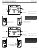
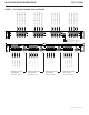
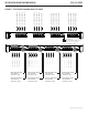
See LED table below and Troubleshooting Guide if corrective action is needed. See figures beginning on page 6 for LED
configurations for each model.
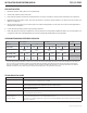
Indicating LEDs
PWR Ethernet Link Ethernet Activity EXT LNK
GREEN Power Applied – Activity Detected 10Mbps
YELLOW – Link Established – 100Mbps
OFF Power Off No Link No Activity No Link
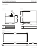
Ethernet
Activity
Ethernet
Link
EXT Link Power
TEU-F01 Only
For 1-pair mode, use the first
pair of pins (pins 1 and 2) of the
“Extended Ethernet” RJ-45 port.