TFT-LCD-TV Chassis Model SERVICE TFT-LCD TV GSM26MLA GSM32MLA GSM40MLA LN26T71B LN32T71B LN40T71B Manual Feature - Luxurious Slim Design - Supreme Picture Quality - Supreme Sound Quality - Supreme Convenience Quality - Convenience for Users
Copyright 2006 by Samsung Electronics Co., Ltd. All rights reserved. This manual may not, in whole or in part, be copied, photocopied, reproduced, translated, or converted to any electronic or machine readable form without prior written permission of Samsung Electronics Co., Ltd. LN26T71B / LN32T71B / LN40T71B Service Manual First edition June 2006. Printed in Korea. ii Trademarks Samsung is the registered trademark of Samsung Electronics Co., Ltd.
Contents
Contents
1 Precautions 1 Precautions Follow these safety, servicing and ESD precautions to prevent damage and to protect against potential hazards such as electrical shock. 1-1 Safety Precautions 1-1-1 Warnings 1. For continued safety, do not attempt to modify the circuit board. 2. Disconnect the AC power and DC Power Jack before servicing. 1-1-2 Servicing the LCD Monitor 1. When servicing the LCD Monitor Disconnect the AC line cord from the AC outlet. 2.
1 Precautions 1-2 Servicing Precautions WARNING: An electrolytic capacitor installed with the wrong polarity might explode. Caution: Before servicing units covered by this service manual, read and follow the Safety Precautions section of this manual. Note: If unforeseen circumstances create conflict between the following servicing precautions and any of the safety precautions, always follow the safety precautions. 1-2-1 General Servicing Precautions 1. 4.
1 Precautions 1-4 Installation Precautions 1. For safety reasons, more than two people are required for carrying the product. 2. Keep the power cord away from any heat emitting devices, as a melted covering may cause fire or electric shock. 3. Do not place the product in areas with poor ventilation such as a bookshelf or closet. The increased internal temperature may cause fire. 6. Keep the antenna far away from any high-voltage cables and install it firmly.
1 Precautions Memo 1-4
2 Product Specifications 2 Product specifications 2-1 Fashion Feature Excellent Picture Quality -DNIe technology provides life-like clear images. Dynamic Contrast -Automatically detects the input visual signal and adjusts to create optimum contrast. Energy saving -Adjusts the brightness of TV so as to reduce the power consumption. SRS TruSurround XT -SRS TruSurround XT provides a virtual Dolby surround system.
2 Product Specifications 2-2 LN26T71B Specifications Item Description ± ° ° 2-2 ° ° ° ° ° °
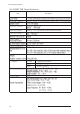
2 Product Specifications 2-3 LN32T71B Specifications Item Description LCD Panel TFT-LCD panel, RGB vertical stripe, normaly white, 32-Inch viewable, 0.511 (H) x 0.511 (V) mm pixel pitchh Scanning Frequency Horizontal : 30 kHz ~ 61 kHz (Automatic) / Vertical : 60 Hz ~ 75 Hz (Automatic) Display Colors 16,777,216 colours Maximum Resolution Horizontal : 1360 Pixels Vertical : 768 Pixels Input Video Signal Analog 0.
2 Product Specifications 2-4 LN40T71B Specifications Item Description LCD Panel TFT-LCD panel, RGB vertical stripe, normaly white, 40-Inch viewable, 0.648(H) x 0.216(V) mm pixel pitch Scanning Frequency Horizontal : 30 kHz ~ 61 kHz (Automatic) / Vertical : 60 Hz ~ 75 Hz (Automatic) Display Colors 16,777,216 colours Maximum Resolution Horizontal : 1360 Pixels Vertical : 768 Pixels Input Video Signal Analog 0.
2 Product Specifications 2-5 Spec Comparison Model LA26R51B / LA32R51B / LA40R51B LN26T71B / LN32T71B / LN40T71B 30 ~ 61 kHz 60 ~ 75 Hz 16,777,216 colors 30 ~ 61 kHz 60 ~ 75 Hz 16,777,216 colors WXGA, 1360 x 768 @ 60 Hz WXGA, 1360 x 768 @ 60 Hz H/V Separate, TTL, P. or N. 0.7 Vp-p @ 75ohm H/V Separate, TTL, P. or N. 0.
2 Product Specifications 2-6 Option Specification Item 2-6 Item Name Code.
3 Alignments and Adjustments 3 Alignments and Adjustments 3-1 Service Instruction 1. Usually, a color TV-VCR needs only slight touch-up adjustment upon installation. Check the basic characteristics such as height, horizontal and vertical sync. 2. Use the specified test equipment or its equivalent. 3. Correct impedance matching is essential. 4. Avoid overload. Excessive signal from a sweep generator might overload the front-end of the TV.
3 Alignments and Adjustments 3-2 How to Access Service Mode 3-2-1 Entering Factory Mode " " - If you have Factory remote - control - The buttons are active in the service mode. 1. Remote - Control Key : Power, Arrow Up, Arrow Down, Arrow Left Arrow Right, Menu, Enter, Number Key(0~9) 2. Function - Control Key : Power, CH +, CH -, VOL +, VOL -, Menu, TV/VIDEO(Enter) 3-2-2 Panel Check Specially for LA26,32R7**, You have to check Panel Maker Because of different adjustments as follows.
3 Alignments and Adjustments 3-3 Factory Data 1. Calibration 2. Option Table 3. White Balance XXXX XXXX 4. SVP-PX 5. Option Block 6. STV8258/STA323W 7. YC Delay 8. Adjust 9. I2C Check 10. W/B MOVIE 11. Checksum 12. Reset 13. Spread Spectrum T-BRDMNUS-1000 (Main Micom Ver) T-BRDMNUSS-1000 (Sub Micom Ver) Month / Day / Year / Hour / Min. / Sec. 1. Calibration 1) AV Calibration 2) DTV Calibration 3) PC Calibration 4) HDMI Calibration 2.
3 Alignments and Adjustments 1. Calibration 2. Option Table 3. White Balance 3-4 AV Calibration EXE DTV Calibration PC Calibration EXE EXE HDMI Calibration EXE Inch Option 26" 32" 40" Gamma Panel Option AUO AUO AUO AUO_AMVA AMLCD AMLCD_INT 2Hdmi Brt.
3 Alignments and Adjustments 4.
3 Alignments and Adjustments Calibration Target low high delta AV ADC COMP ADC 17H D5H 0FH EBH 04H 02H PC ADC ALL RGB 17H D5H 00H DDH 04H 08H Color Management Skin Direction Skin Enhane Reddish 40H 5. Option block EXE 6.
3 Alignments and Adjustments 8. Adjust Video Mute Time 10 Vol Curve Melody Volume Large 4 Ana_Dimm_Max FEH LNA PLUS Hotel Option RFDB-1 Level 2 RFDB-2 Level RFDB-3 Level 5 9 RFDB-4 Level Hotel Mode 24 OFF Power On Channel 1 9. I2C Check 10.
3 Alignments and Adjustments 11. Checksum 12. Reset 13.
3 Alignments and Adjustments 3-4 Service Adjustment 3-4-1 White Balance - Calibration If picture color is wrong, do calibration first. Equipment : CA210, Patten : chess pattern Execute calibration in Factory Mode Source AV : PAL composite, Component : 1280*720/60Hz PC : 1024*768/60Hz ( chess patten ) 3-4-2 White Balance - Adjustment If picture color is wrong, check White Balance condition.
3 Alignments and Adjustments 3-4-3 Conditions for Measurement 1. On the basis of toshiba ABL pattern : High Light level (57 IRE) - INPUT SIGNAL GENERATOR : MSPG-925LTH * Mode NO 1 : 744X484@60 Hz NO 2 : 744X484@60 Hz NO 6 : 1280X720@60 Hz NO 21 : 1024X768@60 Hz * Pattern NO 36 : 16 Color Pattern NO 16 : Toshiba ABL Pattern NO 92 : W/B Pattern 2. Optical measuring device : CA210 (FL) Please use the MSPG-925 LTH generator for model LE26M51B/LE32M51B/LE40M51B/LE46M51B. 3-4-4 Method of Adjustment 1.
3 Alignments and Adjustments Picture 4-3 W/B Patten 3-11
3 Alignments and Adjustments 3-5 Software Upgrade 3-5-1 How to Update Flash ROM 1. Installthe Flash Downloader ConnectSet(Service Jack)and Jig Cable to execute Program Update. 2. Flash Downloader program update -Before Turning on the set,Click "connect"which is under of OSD Screen! -Turn on the Set.
4 Troubleshooting 4 Troubleshooting 4-1 First Checklist for Troubleshooting 1. Check the various cable connections first. - Check to see if there is a burnt or damaged cable. - Check to see if there is a disconnected cable connection or a connection is too loose. - Check to see if the cables are connected according to the connection diagram. 2. Check the power input to the Main Board. 3.
4 Troubleshooting 4-2 Checkpoints by Error Mode 4-2-1 No Power LAMP off, power indicator LED red color? No Check a connection a power cable. Yes Does proper DC 12V appear at CN800? No Change a Assy PCB Power. Yes Does proper DC A3.3V, A5V appear at C854, C866? No Check a IC809, IC802. Change a main PCB ass'y. No Check a IC803, IC805, IC813, IC307. Change a main PCB ass'y No Check a other function. (No picture part) Replace a lcd panel. Yes Does proper DC 5V, 3.3V, 1.
4 Troubleshooting 4-2-2 No Video (Analog PC) Power Indicator is off. Lamp on, no video. Yes Check a PC source and check the connection of DSUB cable? No Input a analog PC signal and connected cable(DPMS). No PC cable. Change a PC cable. Change a main PCB ass'y. No Check a IC500 Change a main PCB ass'y.
4 Troubleshooting WAVEFORMS 1 R,G,B Output Signal of IC500 4-4
4 Troubleshooting 4-2-3 No Video (Digital-HDMI) Power Indicator is off. Lamp on, no video. Yes Check the connection of HDMI cable? No Input a HDMI cable. Yes Does the digital data appear at 3 R503~R510? No Check a a IC 500 Change a main PCB ass'y. No Check a IC500 Change a main PCB ass'y. Yes 2 Does the digital data appear at output of IC500 LVDS(R563_OP~R572_OP)? Yes Check a LVDS cable? Replace lcd panel? No Please, Call to Samsung Co. LTD.
4 Troubleshooting 2 Digital Output Data of IC500 4-6 3 Signal of HDMI(Data)
4 Troubleshooting 4-2-4 No Picture (Tuner_CVBS) Power Indicator is off. Lamp on, no picure. No Connect the RF cable and check RF signal. No Check a B+ voltage (#6 of Tuner) 5V, change a main PCB ass'y Yes 4 Dose the signal appear at R110? Yes 4 Does the signal appear at #8 of IC500? No Change a main PCB ass'y. Yes 3 Does the digital data appear at output of R563_OP~R572_OP? No Check a IC500. Change a main PCB ass'y.
4 Troubleshooting WAVEFORMS 3 CVBS Output Signal 4-8 4 Tuner_CVBS Output Signal
4 Troubleshooting 4-2-5 No Picture (Video_CVBS) Power Indicator is off. Lamp on, no picture. No Check a A/V cable and video signal. Yes 4 Dose the signal appear at #10 of IC500? No Check a connection harness. Yes Does the signal appear at Out of IC500 R563_OP~R572_OP? No Check a IC515. Change a main PCB ass'y Yes Check a LVDS cable? Replace lcd panel? No Please, Call to Samsung Co. LTD.
4 Troubleshooting WAVEFORMS 4 CVBS Output Signal 4-10
4 Troubleshooting 4-2-6 No Picture (S-VIDEO_Y,C) Power Indicator is off. Lamp on, no picure. No Connect the s-video cable. Operating a video player. Yes 5 Dose the Y/C signal appear at No Check a connection harness. #21, #31 of IC500? Yes 2 Does the digital data appear at Output of IC500, R563_OP~R572_OP? No Check a IC500. Change a main PCB ass'y. Yes Check a LVDS cable? Replacea lcd panel? No Please, Call to Samsung Co. LTD.
4 Troubleshooting WAVEFORMS 2 Digital Output Data of IC500 4-12 5 Analog Signal(Y,C) to IC500
4 Troubleshooting 4-2-7 No Sound No Picture is display, no sound. Connect a sound cable. control a volume. Yes Does the signal appear at Pin #10, #16(CH1_L, R Sound) and Pin #3, #9 6 (CH2_L, R Sound) of IC603? No Check a connection harness and headphone jack / Side AV. No Check a IC603. Change a main PCB ass'y. Yes Check the DC 12V of IC603? Yes 7 Does the signal appear at L609_OP, L611_OP, L612_OP, L614_OP? No Change a main PCB ass'y.
4 Troubleshooting WAVEFORMS 6 The Signal are Inputed to IC603 4-14 7 DC +12V
5 Exploded View & Parts List 5 Exploded View and Parts List - You can search for updated part codes through ITSELF web site. URL : http://itself.sec.samsung.co.
5 Exploded View & Parts List 5-2 LN26T71B Parts list Location Code.No Item & Specification T0003 BN96-03174B ASSY COVER P-FRONT;26T71,UO(XAX),HIPS,HB 1 S.A T0175 BN96-03279A ASSY SPEAKER P;16ohm,Sonoma 26,Left,5W,N 1 S.A T0175 BN96-03280A ASSY SPEAKER P;16ohm,Sonoma 26,Right,5W, 1 S.A M0215 BN07-00254A LCD-PANEL;T260XW02,8bit,626.0*373.0*50.0 1 S.A T0447 BN96-03008C ASSY BRACKET P-PANEL;BORDEAUX,26,AUO,SMP 1 S.N.
5 Exploded View & Parts List 5-3 LN32T71B Exploded View T0447 M0215 M0013 T0076 T0003 T0175 T0175 M0013 5-3
5 Exploded View & Parts List 5-4 LN32T71B Parts list Location Code.No Item & Specification T0003 BN96-03175B ASSY COVER P-FRONT;32T71,UO(XAX),-,HIPS, 1 S.A T0175 BN96-03247B ASSY SPEAKER P;8ohm,Yellow/Black,470mm,1 1 S.A T0175 BN96-03248B ASSY SPEAKER P;8ohm,Red/Black,950mm,10W, 1 S.A M0215 BN07-00207A LCD-PANEL;V320B1-L01,Duomo,8bit,760*450* 1 S.A T0447 BN96-02999A ASSY BRACKET P-PANEL;BORDEAUX,32,AMLCD,S 1 S.N.
5 Exploded View & Parts List 5-5 LN40T71B Exploded View M0014 T0447 M0215 M0013 T0076 T0003 T0175 T0175 M0013 5-5
5 Exploded View & Parts List 5-6 LN40T71B Parts list Location Code.No Item & Specification Q'ty SA/SNA T0003 BN96-03184C ASSY COVER P-FRONT;40T71,UO(XAX),HIPS,HB 1 S.A T0175 BN96-03247A ASSY SPEAKER P;8ohm,Sonoma 32,Left,10W,N 1 S.A T0175 BN96-03248A ASSY SPEAKER P;8ohm,Sonoma 32,Right,10W, 1 S.A M0215 BN07-00264A LCD-PANEL;LTA400WT-L01,8bit,952*551*51.0 1 S.A T0447 BN96-03528B ASSY BRACKET P-PANEL;SONOMA,40EO,READY,S 1 S.N.
6 Electrical Parts List 6 Electrical Parts List You can search for updated part codes through ITSELF web site. URL : http://itself.sec.samsung.co.kr/ 6-1 LN26T71B Parts List Level Loc. No. 0 Code No. Description & Specification Q'ty LN26T71BX/XAO LN26T71B,A51O/26T70-GSM,26,LCD-TV,COLOMB 0 SA/SNA 0.1 ..2 ..2 ...3 ...3 ...3 ...3 ...3 ...3 ...3 ...3 ...3 ...3 ...3 ...3 ...3 ...3 ...3 ...3 ..2 ..2 ..
6 Electrical Parts List Level Loc. No. ...3 ...3 ...3 ...3 ...3 ....4 ....4 ....4 ....4 ....4 ....4 ....4 ....4 ....4 ....4 ....4 ....4 ....4 ....4 ....4 ....4 ....4 ....4 ....4 ....4 ....4 ....4 ....4 ....4 ....4 ....4 ....4 ....4 ....4 ....4 ....4 ....4 ....4 ....4 ....4 ....4 ....4 ....4 ....4 ....4 ....4 ....4 ....4 ....4 ....4 ....4 ....4 ....4 ....4 ....4 ....4 ....4 ....4 ....4 ....4 ....4 ....4 ....4 ....4 ....4 ....4 ....4 ....4 ....4 ....4 ....4 ....
6 Electrical Parts List Level Loc. No. ....4 ....4 ....4 ....4 ....4 ....4 ....4 ....4 ....4 ....4 ....4 ....4 ....4 ....4 ....4 ....4 ....4 ....4 ....4 ....4 ....4 ....4 ....4 ....4 ....4 ....4 ....4 ....4 ....4 ....4 ....4 ....4 ....4 ....4 ....4 ....4 ....4 ....4 ....4 ....4 ....4 ....4 ....4 ....4 ....4 ....4 ....4 ....4 ....4 ....4 ....4 ....4 ....4 ....4 ....4 ....4 ....4 ....4 ....4 ....4 ....4 ....4 ....4 ....4 ....4 ....4 ....4 ....4 ....4 ....4 ....4 ....
6 Electrical Parts List Level Loc. No. ....4 ....4 ....4 ....4 ....4 ....4 ....4 ....4 ....4 ....4 ....4 ....4 ....4 ....4 ....4 ....4 ....4 ....4 ....4 ....4 ....4 ....4 ....4 ....4 ....4 ....4 ....4 ....4 ....4 ....4 ....4 ....4 ....4 ....4 ....4 ....4 ....4 ....4 ....4 ....4 ....4 ....4 ....4 ....4 ....4 ....4 ....4 ....4 ....4 ....4 ....4 ....4 ....4 ....4 ....4 ....4 ....4 ....4 ....4 ....4 ....4 ....4 ....4 ....4 ....4 ....4 ....4 ....4 ....4 ....4 ....4 ....
6 Electrical Parts List Level Loc. No. ....4 ....4 ....4 ....4 ....4 ....4 ....4 ....4 ....4 ....4 ....4 ....4 ....4 ....4 ....4 ....4 ....4 ....4 ....4 ....4 ....4 ....4 ....4 ....4 ....4 ....4 ....4 ....4 ....4 ....4 ....4 ....4 ....4 ....4 ....4 ....4 ....4 ....4 ....4 ....4 ....4 ....4 ....4 ....4 ....4 ....4 ....4 ....4 ....4 ....4 ....4 ....4 ....4 ....4 ....4 ....4 ....4 ....4 ....4 ....4 ....4 ....4 ....4 ....4 ....4 ....4 ....4 ....4 ....4 ....4 ....4 ....
6 Electrical Parts List Level Loc. No. ....4 ....4 ....4 ....4 ....4 ....4 ....4 ....4 ....4 ....4 ....4 ....4 ....4 ....4 ....4 ....4 ....4 ....4 ....4 ....4 ....4 ....4 ....4 ....4 ....4 ....4 ....4 ....4 ....4 ....4 ....4 ....4 ....4 ....4 ....4 ....4 ....4 ....4 ....4 ....4 ....4 ....4 ....4 ....4 ....4 ....4 ....4 ....4 ....4 ....4 ....4 ....4 ....4 ....4 ....4 ....4 ....4 ....4 ....4 ....4 ....4 ....4 ....4 ....4 ....4 ....4 ....4 ....4 ....4 ....4 ....4 ....
6 Electrical Parts List Level Loc. No. ....4 ....4 ....4 ....4 ....4 ....4 ....4 ....4 ....4 ....4 ....4 ....4 ....4 ....4 ....4 ....4 ....4 ....4 ....4 ....4 ....4 ....4 ....4 ....4 ....4 ....4 ....4 ....4 ....4 ....4 ....4 ....4 ....4 ....4 ....4 ....4 ....4 ....4 ....4 ....4 ....4 ....4 ....4 ....4 ....4 ....4 ....4 ....4 ....4 ....4 ....4 ....4 ....4 ....4 ....4 ....4 ....4 ....4 ....4 ....4 ....4 ....4 ....4 ....4 ....4 ....4 ....4 ....4 ....4 ....4 ....4 ....
6 Electrical Parts List Level Loc. No. ....4 ....4 ....4 ....4 ....4 ....4 ....4 ....4 ....4 ....4 ....4 ....4 ....4 ....4 ....4 ....4 ....4 ....4 ....4 ....4 ....4 ....4 ....4 ....4 ....4 ....4 ....4 ....4 ....4 ....4 ....4 ....4 ....4 ....4 ....4 ....4 ....4 ....4 ....4 ....4 ....4 ....4 ....4 ....4 ....4 ....4 ....4 ....4 ....4 ....4 ....4 ....4 ....4 ....4 ....4 ....4 ....4 ....4 ....4 ....4 ....4 ....4 ....4 ....4 ....4 ....4 ....4 ....4 ....4 ....4 ....4 ....
6 Electrical Parts List Level Loc. No. ....4 ....4 ....4 ....4 ....4 ....4 ....4 ....4 ....4 ....4 ....4 ....4 ....4 ....4 ....4 ....4 ....4 ....4 ....4 ....4 ....4 ....4 ....4 ....4 ....4 ....4 ....4 ....4 ....4 ....4 ....4 ....4 ....4 ....4 ....4 ....4 ....4 ....4 ....4 ....4 ....4 ....4 ....4 ....4 ....4 ....4 ....4 ....4 ....4 ....4 ....4 ....4 ....4 ....4 ....4 ....4 ....4 ....4 ....4 ....4 ....4 ....4 ....4 ....4 ....4 ....4 ....4 ....4 ....4 ....4 ....4 ....
6 Electrical Parts List Level Loc. No. ....4 ....4 ....4 ....4 ....4 ....4 ....4 ....4 ....4 ....4 ....4 ....4 ....4 ....4 ....4 ....4 ....4 ....4 ....4 ....4 ....4 ....4 ....4 ....4 ....4 ....4 ....4 ....4 ....4 ....4 ....4 ....4 ....4 ....4 ....4 ....4 ....4 ....4 ....4 ....4 ....4 ....4 ....4 ....4 ....4 ....4 ....4 ....4 ....4 ....4 ....4 ....4 ....4 ....4 ....4 ....4 ....4 ....4 ....4 ....4 ....4 ....4 ....4 ....4 ....4 ....4 ....4 ....4 ....4 ....4 ....4 ....
6 Electrical Parts List Level Loc. No. ....4 ....4 ....4 ....4 ....4 ....4 ....4 ....4 ....4 ....4 ....4 ....4 ....4 ....4 ....4 ....4 ....4 ....4 ....4 ....4 ....4 ....4 ....4 ....4 ....4 ....4 ....4 ....4 ....4 ....4 ....4 ....4 ....4 ....4 ....4 ....4 ....4 ....4 ....4 ....4 ....4 ....4 ....4 ....4 ....4 ....4 ....4 ....4 ....4 ....4 ....4 ....4 ....4 ....4 ....4 ....4 ....4 ....4 ....4 ....4 ....4 ....4 ....4 ....4 ....4 ....4 ....4 ....4 ....4 ....4 ....4 ....
6 Electrical Parts List Level Loc. No. ....4 ....4 ....4 ....4 ....4 ....4 ....4 ....4 ....4 ....4 ....4 ....4 ....4 ....4 ....4 ....4 ....4 ....4 ....4 ....4 ....4 ....4 ....4 ....4 ....4 ....4 ....4 ....4 ....4 ....4 ....4 ....4 ....4 ....4 ....4 ....4 ....4 ....4 ....4 ....4 ....4 ....4 ....4 ....4 ....4 ....4 ....4 ....4 ....4 ....4 ....4 ....4 ....4 ....4 ....4 ....4 ....4 ....4 ....4 ....4 ....4 ....4 ....4 ....4 ....4 ....4 ....4 ....4 ....4 ....4 ....4 ....
6 Electrical Parts List Level Loc. No. ....4 ....4 ....4 ....4 ....4 ....4 ....4 ....4 ....4 ....4 ....4 ....4 ....4 ....4 ....4 ....4 ....4 ....4 ....4 ....4 ....4 ....4 ....4 ....4 ....4 ....4 ....4 ....4 ....4 ....4 ....4 ....4 ....4 ....4 ....4 ....4 ....4 ....4 ....4 ....4 ....4 ....4 ....4 ....4 ....4 ....4 ....4 ....4 ....4 ....4 ....4 ....4 ....4 ....4 ....4 ....4 ....4 ....4 ....4 ....4 ....4 ....4 ....4 ....4 ....4 ....4 ....4 ....4 ....4 ....4 ....4 ....
6 Electrical Parts List Level Loc. No. ....4 ....4 ....4 ....4 ....4 ....4 ....4 ....4 ....4 ....4 ....4 ....4 ....4 ....4 ....4 ....4 ....4 ....4 ....4 ....4 ....4 ....4 ....4 ....4 ....4 ....4 ....4 ....4 ....4 ....4 ....4 ....4 ....4 ....4 ....4 ....4 ....4 ....4 ....4 ....4 ....4 ....4 ....4 ....4 ....4 ....4 ....4 ....4 ....4 ....4 ....4 ....4 ....4 ....4 ....4 ....4 ....4 ....4 ....4 ....4 ....4 ....4 ....4 ....4 ....4 ....4 ....4 ....4 ....4 ....4 ....4 ....
6 Electrical Parts List Level Loc. No. Code No. Description & Specification Q'ty SA/SNA ....4 ....4 ....4 ....4 ....4 ....4 ....4 ....4 ....4 ....4 ....4 ....4 ....4 ....4 ....4 ....4 ....4 ....4 ....4 ....4 ....4 ....4 ....4 ....4 ....4 ....4 ....4 ....4 ....4 ....4 ....4 ....4 ....4 ....4 ....4 ....4 ....4 ....4 ....4 ....4 ....4 ....4 ....4 ....4 ....4 ....4 ....4 ....4 ....4 ....4 ....4 ....4 ....4 ....4 ....4 ....4 ....4 ....4 ....4 .....5 ....4 .....5 ....4 ....4 ....4 ....4 ....4 ....4 ...3 ..
6 Electrical Parts List Level Loc. No. ..2 ..2 ..2 ..2 ..2 ..2 ..2 ..2 ..2 ..2 ..2 ..2 ...3 ...3 ...3 ...3 ...3 ...3 ..2 ..2 ..2 ..2 ..2 ..2 ..2 ..2 ..2 M0081 M0081 T0069 M2893 M2893 T0076 M2893 M2893 M0146 M0115 M0114 T0447 M0146 Code No.
6 Electrical Parts List 6-2 LN32T71B Parts List Level Loc. No. 0 Code No. Description & Specification Q'ty LN32T71BX/XAO LN32T71B,A51O/32T70-GSM,32,LCD-TV,COLOMB 0 SA/SNA 0.1 ..2 ..2 ...3 ...3 ...3 ...3 ...3 ...3 ...3 ...3 ...3 ...3 ...3 ...3 ...3 ...3 ...3 ...3 ..2 ..2 ..
6 Electrical Parts List Level ....4 ....4 ....4 ....4 ....4 ....4 ....4 ....4 ....4 ....4 ....4 ....4 ....4 ....4 ....4 ....4 ....4 ....4 ....4 ....4 ....4 ....4 ....4 ....4 ....4 ....4 ....4 ....4 ....4 ....4 ....4 ....4 ....4 ....4 ....4 ....4 ....4 ....4 ....4 ....4 ....4 ....4 ....4 ....4 ....4 ....4 ....4 ....4 ....4 ....4 ....4 ....4 ....4 ....4 ....4 ....4 ....4 ....4 ....4 ....4 ....4 ....4 ....4 ....4 ....4 ....4 ....4 ....4 ....4 ....4 ....4 ....4 6-18 Loc. No.
6 Electrical Parts List Level ....4 ....4 ....4 ....4 ....4 ....4 ....4 ....4 ....4 ....4 ....4 ....4 ....4 ....4 ....4 ....4 ....4 ....4 ....4 ....4 ....4 ....4 ....4 ....4 ....4 ....4 ....4 ....4 ....4 ....4 ....4 ....4 ....4 ....4 ....4 ....4 ....4 ....4 ....4 ....4 ....4 ....4 ....4 ....4 ....4 ....4 ....4 ....4 ....4 ....4 ....4 ....4 ....4 ....4 ....4 ....4 ....4 ....4 ....4 ....4 ....4 ....4 ....4 ....4 ....4 ....4 ....4 ....4 ....4 ....4 ....4 ....4 Loc. No.
6 Electrical Parts List Level ....4 ....4 ....4 ....4 ....4 ....4 ....4 ....4 ....4 ....4 ....4 ....4 ....4 ....4 ....4 ....4 ....4 ....4 ....4 ....4 ....4 ....4 ....4 ....4 ....4 ....4 ....4 ....4 ....4 ....4 ....4 ....4 ....4 ....4 ....4 ....4 ....4 ....4 ....4 ....4 ....4 ....4 ....4 ....4 ....4 ....4 ....4 ....4 ....4 ....4 ....4 ....4 ....4 ....4 ....4 ....4 ....4 ....4 ....4 ....4 ....4 ....4 ....4 ....4 ....4 ....4 ....4 ....4 ....4 ....4 ....4 ....4 6-20 Loc. No.
6 Electrical Parts List Level ....4 ....4 ....4 ....4 ....4 ....4 ....4 ....4 ....4 ....4 ....4 ....4 ....4 ....4 ....4 ....4 ....4 ....4 ....4 ....4 ....4 ....4 ....4 ....4 ....4 ....4 ....4 ....4 ....4 ....4 ....4 ....4 ....4 ....4 ....4 ....4 ....4 ....4 ....4 ....4 ....4 ....4 ....4 ....4 ....4 ....4 ....4 ....4 ....4 ....4 ....4 ....4 ....4 ....4 ....4 ....4 ....4 ....4 ....4 ....4 ....4 ....4 ....4 ....4 ....4 ....4 ....4 ....4 ....4 ....4 ....4 ....4 Loc. No.
6 Electrical Parts List Level ....4 ....4 ....4 ....4 ....4 ....4 ....4 ....4 ....4 ....4 ....4 ....4 ....4 ....4 ....4 ....4 ....4 ....4 ....4 ....4 ....4 ....4 ....4 ....4 ....4 ....4 ....4 ....4 ....4 ....4 ....4 ....4 ....4 ....4 ....4 ....4 ....4 ....4 ....4 ....4 ....4 ....4 ....4 ....4 ....4 ....4 ....4 ....4 ....4 ....4 ....4 ....4 ....4 ....4 ....4 ....4 ....4 ....4 ....4 ....4 ....4 ....4 ....4 ....4 ....4 ....4 ....4 ....4 ....4 ....4 ....4 ....4 6-22 Loc. No.
6 Electrical Parts List Level ....4 ....4 ....4 ....4 ....4 ....4 ....4 ....4 ....4 ....4 ....4 ....4 ....4 ....4 ....4 ....4 ....4 ....4 ....4 ....4 ....4 ....4 ....4 ....4 ....4 ....4 ....4 ....4 ....4 ....4 ....4 ....4 ....4 ....4 ....4 ....4 ....4 ....4 ....4 ....4 ....4 ....4 ....4 ....4 ....4 ....4 ....4 ....4 ....4 ....4 ....4 ....4 ....4 ....4 ....4 ....4 ....4 ....4 ....4 ....4 ....4 ....4 ....4 ....4 ....4 ....4 ....4 ....4 ....4 ....4 ....4 ....4 Loc. No.
6 Electrical Parts List Level ....4 ....4 ....4 ....4 ....4 ....4 ....4 ....4 ....4 ....4 ....4 ....4 ....4 ....4 ....4 ....4 ....4 ....4 ....4 ....4 ....4 ....4 ....4 ....4 ....4 ....4 ....4 ....4 ....4 ....4 ....4 ....4 ....4 ....4 ....4 ....4 ....4 ....4 ....4 ....4 ....4 ....4 ....4 ....4 ....4 ....4 ....4 ....4 ....4 ....4 ....4 ....4 ....4 ....4 ....4 ....4 ....4 ....4 ....4 ....4 ....4 ....4 ....4 ....4 ....4 ....4 ....4 ....4 ....4 ....4 ....4 ....4 6-24 Loc. No.
6 Electrical Parts List Level ....4 ....4 ....4 ....4 ....4 ....4 ....4 ....4 ....4 ....4 ....4 ....4 ....4 ....4 ....4 ....4 ....4 ....4 ....4 ....4 ....4 ....4 ....4 ....4 ....4 ....4 ....4 ....4 ....4 ....4 ....4 ....4 ....4 ....4 ....4 ....4 ....4 ....4 ....4 ....4 ....4 ....4 ....4 ....4 ....4 ....4 ....4 ....4 ....4 ....4 ....4 ....4 ....4 ....4 ....4 ....4 ....4 ....4 ....4 ....4 ....4 ....4 ....4 ....4 ....4 ....4 ....4 ....4 ....4 ....4 ....4 ....4 Loc. No.
6 Electrical Parts List Level ....4 ....4 ....4 ....4 ....4 ....4 ....4 ....4 ....4 ....4 ....4 ....4 ....4 ....4 ....4 ....4 ....4 ....4 ....4 ....4 ....4 ....4 ....4 ....4 ....4 ....4 ....4 ....4 ....4 ....4 ....4 ....4 ....4 ....4 ....4 ....4 ....4 ....4 ....4 ....4 ....4 ....4 ....4 ....4 ....4 ....4 ....4 ....4 ....4 ....4 ....4 ....4 ....4 ....4 ....4 ....4 ....4 ....4 ....4 ....4 ....4 ....4 ....4 ....4 ....4 ....4 ....4 ....4 ....4 ....4 ....4 ....4 6-26 Loc. No.
6 Electrical Parts List Level ....4 ....4 ....4 ....4 ....4 ....4 ....4 ....4 ....4 ....4 ....4 ....4 ....4 ....4 ....4 ....4 ....4 ....4 ....4 ....4 ....4 ....4 ....4 ....4 ....4 ....4 ....4 ....4 ....4 ....4 ....4 ....4 ....4 ....4 ....4 ....4 ....4 ....4 ....4 ....4 ....4 ....4 ....4 ....4 ....4 ....4 ....4 ....4 ....4 ....4 ....4 ....4 ....4 ....4 ....4 ....4 ....4 ....4 ....4 ....4 ....4 ....4 ....4 ....4 ....4 ....4 ....4 ....4 ....4 ....4 ....4 ....4 Loc. No.
6 Electrical Parts List Level ....4 ....4 ....4 ....4 ....4 ....4 ....4 ....4 ....4 ....4 ....4 ....4 ....4 ....4 ....4 ....4 ....4 ....4 ....4 ....4 ....4 ....4 ....4 ....4 ....4 ....4 ....4 ....4 ....4 ....4 ....4 ....4 ....4 ....4 ....4 ....4 ....4 ....4 ....4 ....4 ....4 ....4 ....4 ....4 ....4 ....4 ....4 ....4 ....4 ....4 ....4 ....4 ....4 ....4 ....4 ....4 ....4 ....4 ....4 ....4 ....4 ....4 ....4 ....4 ....4 ....4 ....4 ....4 ....4 ....4 ....4 ....4 6-28 Loc. No.
6 Electrical Parts List Level ....4 ....4 ....4 ....4 ....4 ....4 ....4 ....4 ....4 ....4 ....4 ....4 ....4 ....4 ....4 ....4 ....4 ....4 ....4 ....4 ....4 ....4 ....4 ....4 ....4 ....4 ....4 ....4 ....4 ....4 ....4 ....4 ....4 ....4 ....4 ....4 ....4 ....4 ....4 ....4 ....4 ....4 ....4 ....4 ....4 ....4 ....4 ....4 ....4 ....4 ....4 ....4 ....4 ....4 ....4 ....4 ....4 ....4 ....4 ....4 ....4 ....4 ....4 ....4 ....4 ....4 ....4 ....4 ....4 ....4 ....4 ....4 Loc. No.
6 Electrical Parts List Level ....4 ....4 ....4 ....4 ....4 ....4 ....4 ....4 ....4 ....4 ....4 ....4 ....4 ....4 ....4 ....4 ....4 ....4 ....4 ....4 ....4 ....4 ....4 ....4 ....4 ....4 ....4 ....4 ....4 ....4 ....4 ....4 ....4 ....4 ....4 ....4 ....4 ....4 ....4 ....4 ....4 ....4 ....4 ....4 ....4 ....4 ....4 ....4 ....4 ....4 ....4 ....4 ....4 ....4 ....4 ....4 ....4 ....4 ....4 ....4 ....4 ....4 ....4 ....4 ....4 ....4 ....4 ....4 ....4 ....4 ....4 ....4 6-30 Loc. No.
6 Electrical Parts List Level Loc. No. Code No. Description & Specification Q'ty SA/SNA ....4 ....4 ....4 ....4 ....4 ....4 ....4 ....4 ....4 ....4 ....4 ....4 ....4 ....4 ....4 ....4 ....4 .....5 ....4 .....5 ....4 ....4 ....4 ....4 ....4 ....4 ...3 ...
6 Electrical Parts List Level Loc. No. Code No. Description & Specification Q'ty SA/SNA 0.1 M0019 BN92-02002R ASSY LABEL;LN32T71BX/XAO 1 S.N.A 0.1 ..2 ...3 ...3 ...3 ...3 ...3 ...3 ...3 ...3 ...3 ....4 ....
6 Electrical Parts List 6-3 LN40T71B Parts List Level Loc. No. 0 Code No. Description & Specification Q'ty LN40T71BX/XAO LN40T71B,A51O/40T70-GSM,40,LCD-TV,COLOMB 0 SA/SNA 0.1 ..2 ..2 ...3 ...3 ...3 ...3 ...3 ...3 ...3 ...3 ...3 ...3 ...3 ...3 ...3 ...3 ...3 ...3 ..2 ..2 ..
6 Electrical Parts List Level Loc. No. ....4 ....4 ....4 ....4 ....4 ....4 ....4 ....4 ....4 ....4 ....4 ....4 ....4 ....4 ....4 ....4 ....4 ....4 ....4 ....4 ....4 ....4 ....4 ....4 ....4 ....4 ....4 ....4 ....4 ....4 ....4 ....4 ....4 ....4 ....4 ....4 ....4 ....4 ....4 ....4 ....4 ....4 ....4 ....4 ....4 ....4 ....4 ....4 ....4 ....4 ....4 ....4 ....4 ....4 ....4 ....4 ....4 ....4 ....4 ....4 ....4 ....4 ....4 ....4 ....4 ....4 ....4 ....4 ....4 ....4 ....4 ....
6 Electrical Parts List Level Loc. No. ....4 ....4 ....4 ....4 ....4 ....4 ....4 ....4 ....4 ....4 ....4 ....4 ....4 ....4 ....4 ....4 ....4 ....4 ....4 ....4 ....4 ....4 ....4 ....4 ....4 ....4 ....4 ....4 ....4 ....4 ....4 ....4 ....4 ....4 ....4 ....4 ....4 ....4 ....4 ....4 ....4 ....4 ....4 ....4 ....4 ....4 ....4 ....4 ....4 ....4 ....4 ....4 ....4 ....4 ....4 ....4 ....4 ....4 ....4 ....4 ....4 ....4 ....4 ....4 ....4 ....4 ....4 ....4 ....4 ....4 ....4 ....
6 Electrical Parts List Level Loc. No. ....4 ....4 ....4 ....4 ....4 ....4 ....4 ....4 ....4 ....4 ....4 ....4 ....4 ....4 ....4 ....4 ....4 ....4 ....4 ....4 ....4 ....4 ....4 ....4 ....4 ....4 ....4 ....4 ....4 ....4 ....4 ....4 ....4 ....4 ....4 ....4 ....4 ....4 ....4 ....4 ....4 ....4 ....4 ....4 ....4 ....4 ....4 ....4 ....4 ....4 ....4 ....4 ....4 ....4 ....4 ....4 ....4 ....4 ....4 ....4 ....4 ....4 ....4 ....4 ....4 ....4 ....4 ....4 ....4 ....4 ....4 ....
6 Electrical Parts List Level Loc. No. ....4 ....4 ....4 ....4 ....4 ....4 ....4 ....4 ....4 ....4 ....4 ....4 ....4 ....4 ....4 ....4 ....4 ....4 ....4 ....4 ....4 ....4 ....4 ....4 ....4 ....4 ....4 ....4 ....4 ....4 ....4 ....4 ....4 ....4 ....4 ....4 ....4 ....4 ....4 ....4 ....4 ....4 ....4 ....4 ....4 ....4 ....4 ....4 ....4 ....4 ....4 ....4 ....4 ....4 ....4 ....4 ....4 ....4 ....4 ....4 ....4 ....4 ....4 ....4 ....4 ....4 ....4 ....4 ....4 ....4 ....4 ....
6 Electrical Parts List Level Loc. No. ....4 ....4 ....4 ....4 ....4 ....4 ....4 ....4 ....4 ....4 ....4 ....4 ....4 ....4 ....4 ....4 ....4 ....4 ....4 ....4 ....4 ....4 ....4 ....4 ....4 ....4 ....4 ....4 ....4 ....4 ....4 ....4 ....4 ....4 ....4 ....4 ....4 ....4 ....4 ....4 ....4 ....4 ....4 ....4 ....4 ....4 ....4 ....4 ....4 ....4 ....4 ....4 ....4 ....4 ....4 ....4 ....4 ....4 ....4 ....4 ....4 ....4 ....4 ....4 ....4 ....4 ....4 ....4 ....4 ....4 ....4 ....
6 Electrical Parts List Level Loc. No. ....4 ....4 ....4 ....4 ....4 ....4 ....4 ....4 ....4 ....4 ....4 ....4 ....4 ....4 ....4 ....4 ....4 ....4 ....4 ....4 ....4 ....4 ....4 ....4 ....4 ....4 ....4 ....4 ....4 ....4 ....4 ....4 ....4 ....4 ....4 ....4 ....4 ....4 ....4 ....4 ....4 ....4 ....4 ....4 ....4 ....4 ....4 ....4 ....4 ....4 ....4 ....4 ....4 ....4 ....4 ....4 ....4 ....4 ....4 ....4 ....4 ....4 ....4 ....4 ....4 ....4 ....4 ....4 ....4 ....4 ....4 ....
6 Electrical Parts List Level Loc. No. ....4 ....4 ....4 ....4 ....4 ....4 ....4 ....4 ....4 ....4 ....4 ....4 ....4 ....4 ....4 ....4 ....4 ....4 ....4 ....4 ....4 ....4 ....4 ....4 ....4 ....4 ....4 ....4 ....4 ....4 ....4 ....4 ....4 ....4 ....4 ....4 ....4 ....4 ....4 ....4 ....4 ....4 ....4 ....4 ....4 ....4 ....4 ....4 ....4 ....4 ....4 ....4 ....4 ....4 ....4 ....4 ....4 ....4 ....4 ....4 ....4 ....4 ....4 ....4 ....4 ....4 ....4 ....4 ....4 ....4 ....4 ....
6 Electrical Parts List Level Loc. No. ....4 ....4 ....4 ....4 ....4 ....4 ....4 ....4 ....4 ....4 ....4 ....4 ....4 ....4 ....4 ....4 ....4 ....4 ....4 ....4 ....4 ....4 ....4 ....4 ....4 ....4 ....4 ....4 ....4 ....4 ....4 ....4 ....4 ....4 ....4 ....4 ....4 ....4 ....4 ....4 ....4 ....4 ....4 ....4 ....4 ....4 ....4 ....4 ....4 ....4 ....4 ....4 ....4 ....4 ....4 ....4 ....4 ....4 ....4 ....4 ....4 ....4 ....4 ....4 ....4 ....4 ....4 ....4 ....4 ....4 ....4 ....
6 Electrical Parts List Level Loc. No. ....4 ....4 ....4 ....4 ....4 ....4 ....4 ....4 ....4 ....4 ....4 ....4 ....4 ....4 ....4 ....4 ....4 ....4 ....4 ....4 ....4 ....4 ....4 ....4 ....4 ....4 ....4 ....4 ....4 ....4 ....4 ....4 ....4 ....4 ....4 ....4 ....4 ....4 ....4 ....4 ....4 ....4 ....4 ....4 ....4 ....4 ....4 ....4 ....4 ....4 ....4 ....4 ....4 ....4 ....4 ....4 ....4 ....4 ....4 ....4 ....4 ....4 ....4 ....4 ....4 ....4 ....4 ....4 ....4 ....4 ....4 ....
6 Electrical Parts List Level Loc. No. ....4 ....4 ....4 ....4 ....4 ....4 ....4 ....4 ....4 ....4 ....4 ....4 ....4 ....4 ....4 ....4 ....4 ....4 ....4 ....4 ....4 ....4 ....4 ....4 ....4 ....4 ....4 ....4 ....4 ....4 ....4 ....4 ....4 ....4 ....4 ....4 ....4 ....4 ....4 ....4 ....4 ....4 ....4 ....4 ....4 ....4 ....4 ....4 ....4 ....4 ....4 ....4 ....4 ....4 ....4 ....4 ....4 ....4 ....4 ....4 ....4 ....4 ....4 ....4 ....4 ....4 ....4 ....4 ....4 ....4 ....4 ....
6 Electrical Parts List Level Loc. No. ....4 ....4 ....4 ....4 ....4 ....4 ....4 ....4 ....4 ....4 ....4 ....4 ....4 ....4 ....4 ....4 ....4 ....4 ....4 ....4 ....4 ....4 ....4 ....4 ....4 ....4 ....4 ....4 ....4 ....4 ....4 ....4 ....4 ....4 ....4 ....4 ....4 ....4 ....4 ....4 ....4 ....4 ....4 ....4 ....4 ....4 ....4 ....4 ....4 ....4 ....4 ....4 ....4 ....4 ....4 ....4 ....4 ....4 ....4 ....4 ....4 ....4 ....4 ....4 ....4 ....4 ....4 ....4 ....4 ....4 ....4 ....
6 Electrical Parts List Level Loc. No. ....4 ....4 ....4 ....4 ....4 ....4 ....4 ....4 ....4 ....4 ....4 ....4 ....4 ....4 ....4 ....4 ....4 ....4 ....4 ....4 ....4 ....4 ....4 ....4 ....4 ....4 ....4 ....4 ....4 ....4 ....4 ....4 ....4 ....4 ....4 ....4 ....4 ....4 ....4 ....4 ....4 ....4 ....4 ....4 ....4 ....4 ....4 ....4 ....4 ....4 ....4 ....4 ....4 ....4 ....4 ....4 ....4 ....4 ....4 ....4 ....4 ....4 ....4 ....4 ....4 ....4 ....4 ....4 ....4 ....4 ....4 ....
6 Electrical Parts List Level Loc. No. ....4 ....4 ....4 ....4 ....4 ....4 ....4 ....4 ....4 ....4 ....4 ....4 ....4 ....4 ....4 ....4 ....4 ....4 ....4 ....4 ....4 ....4 ....4 ....4 ....4 ....4 ....4 ....4 ....4 ....4 ....4 ....4 ....4 ....4 ....4 ....4 ....4 ....4 ....4 ....4 ....4 ....4 ....4 ....4 ....4 ....4 ....4 ....4 ....4 ....4 ....4 ....4 ....4 ....4 ....4 ....4 ....4 ....4 ....4 ....4 ....4 ....4 ....4 ....4 ....4 ....4 ....4 ....4 ....4 ....4 ....4 ....
6 Electrical Parts List Level Loc. No. ....4 ....4 ....4 ....4 ....4 ....4 ....4 ....4 ....4 ....4 ....4 ....4 ....4 ....4 ....4 ....4 ....4 .....5 ....4 .....5 ....4 ....4 ....4 ....4 ....4 ....4 ...3 ...
6 Electrical Parts List Level Loc. No. Code No. Description & Specification Q'ty SA/SNA 0.1 ..2 M0003 T0130 BN92-01699R BN69-01310M ASSY BOX;40T71,UO,(READY,GSU),-,-,SONOMA BOX-00,SET;40T7(OVERSEA),DY-01,AB,YEL,A1 1 1.01 S.N.A S.N.A 0.1 ..2 ..2 ..2 ..2 M0113 T0376 T0376 T0003 T0524 BN92-01702A 6902-000061 6902-000379 6902-000604 6902-000411 ASSY P/MATERIAL;40T70,SONOMA BAG AIR;LDPE,T0.2,L1000,W500,TRP,,, BAG AIR;LDPE,T0.2,W1000,L1800,TRP,-,-BAG WRAPPING;LDPE,T0.
8 Wiring Diagrams 8 Wiring Diagram 8-1 LN26T71B / LN32T71B / LN40T71B Wiring Diagram 8-1
8 Wiring Diagrams 8-2 Main Board Layout 8-2
8 Wiring Diagrams 8-3 PIN characteristic CN800 - Main Board power supply PIN 1 NAME B12V Function Define - B12V - B5V - B12VS - A5V 2 3 4 5 6 7 GND B5V B5V B5V GND GND 8 9 10 11 12 GND B12VS B12VS B12VS GND 13 14 15 16 GND GND A5V A5V B8V, B5V-T B5V-1, B5V, 5V-P, B1.8V B12VS A5V, A3.3V-3, A3.3V, A3.3V-1, B3.3V, A1.
8 Wiring Diagrams CN221 - Front control PIN 1 2 3 NAME SDA-T SCL-T GND 4 5 6 7 8 9 10 11 KEY LED GND A5V GND IR KEY KEY INPUT1 INPUT1 INPUT2 Function Define - A5V Front control board poewr supply - KEY INPUT1,2/SDA/SCL Key control, from the memu, change up/down Etc.
8 Wiring Diagrams 8-5
8 Wiring Diagrams 8-4 Power Board Layout 8-6
8 Wiring Diagrams CN801 - AC Input PIN I 2 NAME Live Netural VOLTAGE AC AC Functing Define - Refer to : AC Input CN801 - Main Board power supply PIN 1 2 NAME 13V 3 GND 5.4V 4 5 6 7 8 9 10 11 12 13 5.4V 5.
8 Wiring Diagrams CN802 - Inverter power supply PIN 1 2 3 4 5 6 7 NAME 24V 24V 24V 24V 24V GND GND Functing Define - AMLCD - 24V - B/L - A_D - P_D 8 9 GND GND 10 11 12 13 14 GND GND B/L A_D P_D 10 11 12 13 14 GND A_D B/L P_D GND Panel Inverter Power LAMP INVERTER Voltage Brightness sensor power ANA_DIMMING PWM_DIMMING CN803 - Inverter power supply PIN 1 2 3 4 5 6 7 NAME 24V 24V 24V 24V 24V GND GND Functing Define - AUO - 24V - B/L - A_D - P_D 8-8
8 Wiring Diagrams 8-9
8 Wiring Diagrams CN801 - AC Input PIN I 2 NAME Live Netural VOLTAGE AC AC Functing Define - Refer to : AC Input CN801 - Main Board power supply PIN 1 2 NAME 13V 3 GND 5.4V 4 5 6 7 8 9 10 11 12 13 5.4V 5.
8 Wiring Diagrams CN803 - Inverter power supply PIN 1 2 3 4 5 6 7 NAME 24V 24V 24V 24V 24V GND GND Functing Define - AMLCD - 24V - B/L - A_D - P_D 8 9 GND GND 10 11 12 13 14 GND GND B/L A_D P_D 10 11 12 13 14 GND B/D P_L GND B/L Panel Inverter Power LAMP INVERTER Voltage Brightness sensor power ANA_DIMMING PWM_DIMMING CN804 - Inverter power supply PIN 1 2 3 4 5 6 7 NAME 24V 24V 24V 24V 24V GND GND Functing Define - CMO - 24V - B/L - P_D 8 9 GND
8 Wiring Diagrams Memo 8-12
9 Schematic Diagrams 9 Schematic Diagrams -This Document can not be used without Samsung's authorization. 9-1 Power_Sound Schematic Diagram B8V PO W ER B12V B5V B12VS B5V_VCCT TP800 C805 C800 TP949 TP950 MC33269DTRK-5.0 3 3 BA178M08FP 1 IN < TORINO SMPS > OUT 1 I 2 O SOUND L101 3.
9 Schematic Diagrams ’ 9-2 Jack Schematic Diagram SC A R T1 JA701_EU SC1_SR_OUT JA716 SC1_SL_OUT 470ohm R407 SC1_COMP2_SL_IN XREF TP405 TP406 1 2 3 4 5 6 7 8 9 10 11 12 13 14 15 16 17 18 19 20 21 C403 100pF C402_EU 100pF 100pF AGND_IN R414 47ohm R415 47ohm R418 47ohm XREF D418 XREF R430_EU R420_EU D422_EU D423_EU D424_EU 3 R490_EU 3 R425 3 R424 3 R423 XREF 1/10W 51ohm R422_EU D410_NT B5V_VCCA D411_NT 1 SC1_B_COMP2_Pb TP415 TP416 SC1_G_COMP2_Y 330ohm R408 470oh
9 Schematic Diagrams ’ 9-3 Micom Schematic Diagram 9-3
9 Schematic Diagrams ’ 9-4 SVP-PX/PX-Power/LBE-Option Schematic Diagram 9-4
9 Schematic Diagrams ’ 9-5 Application Schematic Diagram 9-5
9 Schematic Diagrams Memo 9-6
10 Operating Instructions and Installation 10 Operating Instructions and Installation 10-1 Front - The product color and shape may vary depending on the model. 1. SOURCE 5. SPEAKERS Toggles between all the available input sources (TV, AV1, AV2, S-Video1, S-Video2, Component, PC, 6. REMOTE CONTROL SENSOR HDMI1, HDMI2). Aim the remote control towards this spot on the TV. In the on-screen menu, use this button as you would use the ENTER button on the remote control. 7.
10 Operating Instructions and Installation 10-2 Connection Panel LN-S2641D LN-S3241D / LN-S4041D 1. AV IN 1 Video and audio inputs for external devices, such as a camcorder or VCR. S-VIDEO 1 Connect an S-Video signal from a camcorder or VCR. 2. AUDIO OUT Connect to the audio input jacks on your Amplifier/ Home theater. 3. DIGITAL AUDIO OUT (OPTICAL) Connect to a Digital Audio component. 4. SERVICE 1/SERVICE 2 Connector for service only. 5.
10 Operating Instructions and Installation 10-2-1 Side Panel Jacks(LN32T71B / LN40T71B) - Use the left side panel jacks to connect a component that is used only occasionally, such as a camcorder or video game. 1. AV IN 2 Video and audio inputs for external devices. S-VIDEO IN 2 Video inputs for external devices with an S-Video output. 2. HEADPHONE Connect a set of external headphones for private lis tening.
10 Operating Instructions and Installation 10-3 Remote Control - This is a special remote control for the visually impaired, and has Braille points on the Power, Channel and Volume buttons.
10 Operating Instructions and Installation 10-5
10 Operating Instructions and Installation Memo 10-6
11 Disassembly and Reassembly 11 Disassembly and Reassembly This section of the service manual describes the disassembly and reassembly procedures for the TFT-LCD TV. WARNING : This monitor contains electrostatically sensitive devices. Use caution when handling these components. 11-1 Disassembly Cautions : 1. Disconnect the monitor from the power source before disassembly. 2. Follow these directions carefully; never use metal instruments to pry apart the cabinet. Description Picture Description 1.
11 Disassembly and Reassembly Description 2. Lift up the rear cover and remove the stand. 3. Remove screws from the stand BRKT and lift up the stand BRKT.
11 Disassembly and Reassembly Description Picture Description 4. Disonnect cables from the boards. 5. Remove screws from the boards and lift up the boards.
11 Disassembly and Reassembly Description 6. Remove screw from the side connector. Remove screws from the panel BRKT. 7. Lift up the panel BRKT.
11 Disassembly and Reassembly Description Picture Description 8. Lift up the LCD panel. 11-2 Reassembly Reassembly procedures are in the reverse order of disassembly procedures.
11 Disassembly and Reassembly Memo 11-6
12 PCB Diagram 12 PCB Diagram 12-1 26" Main PCB Diagram 12-1
12 PCB Diagram 12-2 32" , 40" Main PCB Diagram 12-2
12 PCB Diagram 12-3 26" SMPS board 12-3
12 PCB Diagram 12-4 32" SMPS board 12-4
12 PCB Diagram 12-5 40" IP Board 12-5
12 PCB Diagram Memo 12-6
13 Circuit Descriptions 13 Circuit Descriptions 13-1 Block description 13-1-1 Block description with IP Board Bordeaux consists of three main blocks 1. Main board : Video signal processing 2. IP board : Power supply & Inverter 3.
13 Circuit Descriptions 13-1-2 Block description with SMPS Bordeaux consists of three main blocks 1. Main board : Video signal processing 2. SMPS : Power supply 3.
13 Circuit Descriptions 13-2 Main Block 13-3
13 Circuit Descriptions 13-3 SMPS Board 13-3-1 26", 32" SMPS Block 13-3-2 26", 32" SMPS Block 13-4
13 Circuit Descriptions 13-3-3 26" , 32" SMPS Block 13-3-4 26" , 32" SMPS Block 13-5
13 Circuit Descriptions 13-6
13 Circuit Descriptions 13-3-5 32" , 40" IP Board 13-3-6 32" , 40" IP Board 13-7
13 Circuit Descriptions Memo 13-8
14 Reference Infomation 14 Reference Infomation 14-1 Technical Terms - TFT-LCD - Auto Configuration(Auto adjustment) (Thin film Transistor Liquid Crystal Display) ADC(Analog to Digital Converter) This is an algorithm to adjust monitor to optimum condition by pushing one key. This is a circuit that converts from analog signal to digital signals. - OSD(On Screen Display) On screen display. customer can control the screen easily with this.
14 Reference Infomation - T.M.D.S - Interlace and Non-Interlace Methods (Transition minimized Differential Signaling) a kind of transmission method for Digital. Showing the horizontal lines of the screen from the top to the bottom in order is called the Non- It can be used from Video card to Main PBA. Interlace method while showing odd lines and then even lines in turn is called the Interlace method.
14 Reference Infomation - Satellite Broadcasting - Channel Fine Tuning Broadcasting service provided via satellite. Enables high picture quality and clear sound This feature allows the viewer to fine-tune the TV channel to obtain the best viewing conditions. The throughout the country regardless of the location of the viewer. Samsung LCD TV has both automatic and manual channel fine-tuning features to enable the viewer to adjust their desired settings.
14 Reference Infomation 14-2 Pin Assignments 14-2-1 DVI-D Sync Type Pin No. 24P DVI-D 1 Rx2- 13 NC 2 Rx2+ 14 DDC Input power (+5V) 3 GND 15 IDENT-DVI 4 NC 16 Output Signal (HDCP Control) 5 NC 17 Rx0- 6 DDC - SCL 18 Rx0+ 7 DDC - SDA 19 GND 8 NC 20 NC 9 Rx1- 21 NC 10 Rx1+ 22 GND 11 GND 23 RxC+ 12 NC 24 RxC- Figure 1.
14 Reference Infomation 14-2-2 Component 14-2-3 S-Video Y Pin Separate GND 1 2 3 4 5 GND Y C GND GND RCA Green Pb (Cb) RCA Blue GND Pr (Cr) RCA Red GND Audio L 14-2-5 D-SUB RCA White GND Audio R RCA Red GND 14-2-4 A/V RCA Yellow CVBS Audio L RCA White GND Audio R RCA Red GND Pin Separate 1 2 3 4 5 6 7 8 9 10 11 12 13 14 15 Red Green Blue GND GND GND Red GND Green GND Blue DDC Input power(+5V) IDENT PC GND DDC Data(SDA) H SYNC V SYNC DDC Clock(SCL) 14-2-6 PC Display mode Both screen positi
14 Reference Infomation 14-3 Timing Chart This section of the service manual describes the timing that the computer industry recognizes as standard for computergenerated video signals.
14 Reference Infomation 14-3-2 Supported Modes (1) 14-7
14 Reference Infomation 14-3-3 Supported Modes (2) 14-8
14 Reference Infomation 14-3-4 Supported Modes (3) 14-9
14 Reference Infomation 14-4 Panel Description Maker VENDOR P/N PANEL_CODE PANEL_ABB STICKER_CODE SEC LT140X1-002 BN07-00004A SA SEC LT150XS-L01 BN07-00009A SB - SEC LT150XS-L01-B BN07-00022A SC - SEC LTM150XS-L02 BN07-00005A SD - SEC LT181E2-132 BN07-00001A SE - SEC LT150XS-T01 BN07-00010A SF - SEC LTM181E3-132 BN07-00019A SG - SEC LT170E2-131 BN07-10001D SH - SEC LT181E2-131 BN07-10001E SJ - SEC LTM170E4-L01 BN07-00018A SK - SEC LTM240W1-L01 BN07-00
14 Reference Infomation Maker VENDOR P/N PANEL_CODE BN07-00109A PANEL_ABB S1 STICKER_CODE Remarks SEC LTA400W1-L01 PANEL of AMLCD 40" TV SEC LTM153W1-L01 BN07-00110A S2 Color coordinates change 0.280/0.290, 10000k & ZPD Panel SEC LTM150XH-L06 BN07-00111A S3 Color coordinates change 0.280/0.290, 10000k & ZPD Panel SEC LTM170W1-L01 BN07-00112A S4 Color coordinates change 0.280/0.290, 10000k & ZPD Panel SEC LTM170EH-L05 BN07-00113A S5 Color coordinates change 0.280/0.
14 Reference Infomation Maker VENDOR P/N PANEL_CODE PANEL_ABB STICKER_CODE Remarks SEC LTA260W2-L01 BN07-00185A SPZ AMLCD 26" 16:9 new Panel SEC LTM240M1-L01 BN07-00195A SPH 24" panel with high brightness deveiopment SEC LTA400W2-L01 BN07-00186A SPZ AMLCD 40" 16:9 new Panel SEC LTM150XO-L01 BN07-00197A STH AMLCD 15" XO-L01 Pb free panel code SEC LTM150XO-L01 BN07-00197B STZ AMLCD 15" XO-L01 Pb free panel ZPD code SEC LTM170EU-L21 BN07-00202A STZ AMLCD EU-L21 ZPD new code
14 Reference Infomation Maker VENDOR P/N PANEL_CODE PANEL_ABB STICKER_CODE Remarks HANNSTAR HSD150MX17-A BN07-00226A NTZ Hannstar 15" slim panel ZPD code derivation TORISAN TM150XG-22L03(A) BN07-00021A RA - TORISAN TM150XG-26L06 BN07-00042A RB - TORISAN TM181SX-76N01 BN07-00048A RC - TORISAN TM150XG-26L06 BN07-00059A RD 15" XGA TN MODE(ZPD) TORISAN TM290WX-71N31 BN07-00063A RE "RS24NS (TORISAN 29"" NEW PANEL)" TORISAN TM396WX-71N31 BN07-00064A RF "RS24NS (TORISAN 40"
14 Reference Infomation Maker VENDOR P/N PANEL_CODE PANEL_ABB STICKER_CODE Remarks ACER M170EN05 BN07-00102A AC ZPD Panel code ACER M190EN02 BN07-00170A AMH "AU Monitor 19"" new panel development (P19-1S)" ACER M190EN02 BN07-00170B AMZ "AU 19"" ZPD code derivation (ZPD)" ACER M170EN06 BN07-00171A ATH "AU Monitor 17"" New panel development " ACER T260XW01 BN07-00163A AMZ "AU 26"" new panel development (NF26EO)" ACER A201SN01 BN07-00177A ATZ "AU TV panel 20.
14 Reference Infomation Memo 14-15
- This Service Manual is a property of Samsung Electronics Co., Ltd. Any unauthorized use of Manual can be punished under applicable International and/or domestic law. Samsung Electronics Co.,Ltd. 416, Maetan-3Dong, Yeongtong-Gu, Suwon City, Gyeonggi-Do, Korea, 443-742 Printed in Korea P/N : BN82-00139U-00 URL : http://itself.sec.samsung.co.