
User's Manual

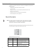


Table Of Contents
- Contents
- Figures
- Introduction
- Installation
- Operation
- Troubleshooting
- Specifications
- Reader Specifications
- Environmental Specifications
- Battery Specifications (Optional)
- Power Supply Specifications
- RS-232 Connector Specifications
- RS-485 Connector Specifications
- RS-485/Ethernet Jumper Setting
- Ethernet LAN Connector Specifications
- Digital I/O Connector Specifications
- Optional Communication Cable Specifications
- Suitable Antenna Specifications
- Regulatory Standards
- Reader Configuration
- Tag Programming
- Configuring the IP Address

MP9320 V2.8 User’s Guide
4
In addition to the scalable, multi-protocol architecture, the MP9320 V2.8 includes the
following features:
• LED indicators (operational and antenna transmit)
• (4) antenna ports
• Multiple host interface connections (RS-232, RS-485, Ethernet LAN)
• Digital input and output lines
• Integrated real-time clock with battery backup (optional)
• On-board temperature sensor (optional)
Physical Description
NOTE: The reader enclosure is designed for office, indoor warehouse, and light
manufacturing areas. If a sealed reader is required for wet or hazardous
environments, contact your SAMSys representative.
The digital board contains four LED indicators to provide the operational status of the
reader. The LEDs are visible on the front panel of the reader.
Figure 3–MP9320 LED Status Indicators
Indicator Color Description
Fault Red Error condition exists
Power Green Power is applied to the reader and
processor initialization complete
Sense Green Reader has tag data to report.This LED
also flashes when the reader software
is being loaded.
Transmit Green Transmitter is operating and RF power
is applied to one of the antennas
Fault
Power
Sense
Transmit