
User's Manual

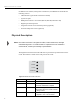


Table Of Contents
- Contents
- Figures
- Introduction
- Installation
- Operation
- Troubleshooting
- Specifications
- Reader Specifications
- Environmental Specifications
- Battery Specifications (Optional)
- Power Supply Specifications
- RS-232 Connector Specifications
- RS-485 Connector Specifications
- RS-485/Ethernet Jumper Setting
- Ethernet LAN Connector Specifications
- Digital I/O Connector Specifications
- Optional Communication Cable Specifications
- Suitable Antenna Specifications
- Regulatory Standards
- Reader Configuration
- Tag Programming
- Configuring the IP Address

Introduction
5
In addition to the status LEDs, four Active Antenna LEDs provide indication that RF
power is being applied to one of the four antennas. Two LEDs (not shown) are also
provided on the Ethernet LAN connector to indicate network communication status.
Figure 4–MP9320 Active Antenna LED Indicators
Four SMA type antenna ports are provided on the end panel. The reader also has one
power and four communication interface connectors on the opposite end panel.
Figure 5–MP9320 V2.8 End-Panel Connectors
Active Antennas
12 34
RS-232 Port
Digital I/O
Port
Antenna
RF Ports
RS-485 Port
Ethernet Port
Power