MP9320 UHF Reader Field Installation and Calibration Guide
Fourth Edition (May 1, 2005) V4.1 © Copyright 2005 SAMSys Technologies, Inc. All Rights Reserved. Disclaimer and Limitation of Liability The content of this manual is for information use only and is subject to change without notice. SAMSys assumes no responsibility or liability for any errors or inaccuracies that may appear in this publication.
Contents Introduction . . . . . . . . . . . . . . . . . . . . . . . . . . . . . . . . . . . . . . . . . . . . . . . . . Assumptions . . . . . . . . . . . . . . . . . . . . . . . . . . . . . . . . . . . . . . . . . . . . . . . . . Getting Technical Assistance . . . . . . . . . . . . . . . . . . . . . . . . . . . . . . . . . . . . Antenna Installation . . . . . . . . . . . . . . . . . . . . . . . . . . . . . . . . . . . . . . . . . . . Antenna Specifications . . . . . . . . . . . . . . . . . . . . . . . . . .
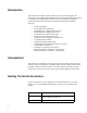
Introduction This document is intended to assist technical service personnel engaged in the installation of the SAMSys MP9320 UHF Reader. The document includes procedures for installing and configuring the reader to meet local standards and regulatory requirements.
Antenna Installation The MP9320 supports from one to four external antennas in a variety of configurations. One- and two-antenna configurations are typical for most conveyor and container tracking. Four-antenna configurations are used for portals and loading dock doorways. Caution For uncontrolled environments (in the general population), the spacing between the antenna(s) and any persons must be at least 9 inches when the reader is operating at full power (4 Watts EIRP).
Antenna Specifications The MP9320 is factory calibrated for operation with the following type of antenna: Antenna Parameter FCC ETSI Frequency 902-928 MHz 865-870 MHz Polarization Circular Circular Gain, dBic 8, max 5, max Antenna power handling 1 W, minimum 1 W, minimum VSWR, maximum 1.3:1 1.
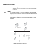
Antenna Installation Procedure It is highly recommended that the antenna mounting be adjustable in order to obtain the best performance from the system. However, the antennas must be installed on a solid surface or frame to prevent damage or later misalignment. Perform the following to install the antennas. NOTE: Use the existing mounting holes on the antenna flange. Drilling new holes in the flange is not recommended. 1. Determine the location of each antenna.
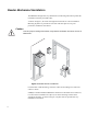
Reader Mechanical Installation The MP9320 is designed for easy installation. The following instructions provide the information to install your UHF reader. As shown in Figure 2, the reader is designed for horizontal or vertical installation. Mounting keyholes are provided on each side of the base plate for easy, nonpermanent, installation and removal. Caution To ensure proper cooling of the reader, verify that the fan intakes and vents are free of obstructions.
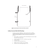
6.40 in (162.5 mm) .359 in Ø (9 mm) 5.0 in (127 mm) Figure 3–MP9320 Base Plate with Mounting Keyholes Hollow Concrete Block Wall Mounting To temporarily mount the MP9320 to a hollow concrete block wall, SAMSys recommends metal sleeve type concrete anchors that accept a #10 screw and flat washer. To install the MP9320 on a hollow concrete block wall, perform the following. 1. Refer to Figure 3, and mark the location of the mounting screws. Do not install the anchors into the mortar joint. 2.
Solid Concrete Wall Mounting To temporarily mount the MP9320 to a solid concrete wall, SAMSys recommends one-piece expansion type concrete anchors that accept a #10 screw and flat washer. To install the MP9320 on a solid concrete wall, perform the following. 1. Refer to Figure 3, and mark the location of the mounting screws. 2. Drill the appropriate size hole for a expansion type anchor. 3. Install the anchors 4. Install the washers and insert the screws. 5. Tighten the screws to within .
RS-485/Ethernet Communication Selection The MP9320 is equipped with both RS-485 and Ethernet communication ports. However, only one can be selected at a time. The reader is typically shipped with Ethernet communication enabled. To enable RS-485 communication, perform the following: Caution - ESD The following procedures involve electrostatic discharge sensitive components. ESD protection is required.
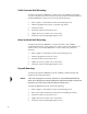
Serial (RS-232) Communication Setup The reader is equipped with a 9-pin RS-232 communication port for communication directly with a PC or other serial device. Refer to the Specifications chapter in the MP9320 User’s Guide for information on the port. ct A 3 S nsm Tra it en se P ow er Fa ul t 1 2 iv e A nte nn a 4 DB-9 Connector de r C EP Re a 2.7 P ow e RS r (1 -4 5 85 Vd & c 2.
9. If the tag did not read correctly, use RF Command Suite to verify the reader operating mode matches the application requirement. If necessary, reconfigure the reader operating modes. NOTE: Refer to the RF Command Suite User’s Guide and the Comprehensive Heuristic Unified Messaging Protocol (CHUMP) Reference Guide for detailed information on configuring the reader. Ethernet LAN Communication Setup The MP9320 can be networked with other readers on an enterprise 10/100 BaseT Ethernet LAN.
Configuring the IP Address The MP9320 is equipped with an optional TCP/IP Ethernet port and embedded IP device server. This reader is configured for automatic IP address allocation using the Dynamic Host Configuration Protocol (DHCP) Mode and the reader automatically extracts the IP address from the DHCP server. This is the default mode for the reader as it is shipped from the factory.
Setting Digital Input for Reader Duty Cycle Control MP9320 readers with software version 1.33.04 or later can be configured for limited duty cycle (trigger enabled RF output) by setting one of the digital inputs. This functionality can be enabled to meet regulatory requirements or to set the reader to respond to external events. In order for the reader to recognize a trigger, the Protocol Control Word (PCW) must be configured. Perform the following to setup the reader for external trigger: 1.
Transmit Power Calibration The MP9320 can be operated with a variety of commercially available antennas and coaxial cables. As a result, the output RF power of the reader must be configured to optimize the read range for a given antenna configuration, while not violating FCC or ETSI regulations. Calibration of the reader transmit RF power must only be performed by SAMSys authorized installation personnel or certified resellers.
Transmitter and Antenna Configuration Multiplexer Configuration Word (MCW) The MCW configures the MP9320 UHF reader. Parameters include the following: • • • • 7 6 5 4 Enable/suppress antenna hopping Enable/suppress MUX failure messages Number of antennas Number of inventory operations before antenna hop.
Multiplexer Select Word (MSW) The MSW selects which antennas are active on the MP9320 UHF reader. The variable also selects the activation order (LSB to MSB). The bit settings for the MSW are shown in Figure 8.
Transmit Power Configuration (TPC) The transmitter configuration is controlled by the 32-bit Transmit Power Configuration (TPC) register. For bit settings, refer to Figure 10. The default setting for this register is 0x00000840. 7 6 5 4 3 2 1 0 Bit Name D0 Tx DAC Pwr D7 15 14 13 12 11 10 9 8 Bit Name D8 Tx DAC Pwr D15 23 22 21 20 19 18 17 16 Bit Name D16 Frequency control Disable Tx drift D17 compensation Function Tx DAC power setting for the current antenna. Bits 0-7.
The following command sets the reader for FCC operation: }Cw,d:tpc,b:00010000,f:1! The following command sets the reader for ETSI operation with Frequency Hopping: }Cw,d:tpc,b:00040000,f:1! NOTE: A change in value for Frequency control or Enable ETSI frequency hopping will reset the reader when it changes modes. Writing these bits to the previous value will not affect the reader since there is no mode change. The reader can internally check antenna condition via the reflected power measurement.
Antenna Transmit Power (TPx) This register sets the antenna power for antenna ports 1, 2, 3,and 4 (TP0, TP1, TP2, and TP3 respectively). Refer to the following sections for calculating the antenna power index values. 7 6 5 4 3 2 1 0 Bit Name D0 Tx DAC Pwr D7 15 14 13 12 11 10 9 8 W X Setting/Function R Tx DAC Pwr Tx DAC power setting for the current antenna. Bits 8-14.
Manual Field Power Calibration - FCC Readers Caution The following procedure involves connecting and disconnecting RF cables from the reader. The reader should be powered down (transmitter disabled) before disconnecting any antenna, cable, or power meter from any port to prevent damaging the unit. Antennas (or a power meter) should be attached to all active ports prior to transmitter power up.
In order to calibrate the reader for 32.5 dBm, use the following table to look-up a corresponding index number to write to the reader. As shown in the following table, 32.5 dBm corresponds to an index of 0e. Index Pout (dBm) (W) Index Pout (dBm) (W) Index Pout (dBm) (mW) Index Pout (dBm) (mW) Index Pout (dBm) (mW) 00 27** 0.5 14 31 1.26 28 26 398 3c 21 126 50 16 40 02 34.7 2.95 16 30.5 1.12 2a 25.5 355 3e 20.5 112 52 15.5 35 04 34.3 2.
Manual Field Power Calibration - ETSI Readers Caution The following procedure involves connecting and disconnecting RF cables from the reader. The reader should be powered down (transmitter disabled) before disconnecting any antenna, cable, or power meter from any port to prevent damaging the unit. Antennas (or a power meter) should be attached to all active ports prior to transmitter power up.
In order to calibrate the reader for 27 dBm, use the following table to look-up a corresponding index number to write to the reader. As shown in the following table, 27 dBm corresponds to an index of 24. Index Pout (dBm) (W) Index Pout (dBm) (W) Index Pout (dBm) (mW) Index Pout (dBm) (mW) Index Pout (dBm) (mW) 00 27** 0.5 14 31 1.26 28 26 398 3c 21 126 50 16 40 02 34.7 2.95 16 30.5 1.12 2a 25.5 355 3e 20.5 112 52 15.5 35 04 34.3 2.