
Installation Guide
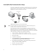


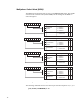

Table Of Contents
- Contents
- Introduction
- Assumptions
- Getting Technical Assistance
- Antenna Installation
- Reader Mechanical Installation
- RS-485/Ethernet Communication Selection
- RS-485 Impedance Matching Selection
- Serial (RS-232) Communication Setup
- Ethernet LAN Communication Setup
- Installing the RF Command Suite Application
- Configuring the IP Address
- Digital (TTL) Input/Output Setup
- Setting Digital Input for Reader Duty Cycle Control
- Transmit Power Calibration
- Transmitter and Antenna Configuration
- Manual Field Power Calibration - FCC Readers
- Manual Field Power Calibration - ETSI Readers

12
Serial (RS-232) Communication Setup
The reader is equipped with a 9-pin RS-232 communication port for communication
directly with a PC or other serial device. Refer to the Specifications chapter in the
MP9320 User’s Guide for information on the port.
Figure 4–MP9320 Standalone RS-232 Communication Setup
NOTE: A serial port adapter may be required if the device has a different connector type. For
example, some PCs may have 25-pin serial connectors.
Every effort has been made to ensure the MP9320 is configured to match your
application. However, it is recommended that the reader configuration be verified
before placing the reader into service. If the system is to be used as a local, standalone
reader connected to a terminal or PC, perform the following:
1. Verify all antennas, cabling and power supplies are secure.
2. Verify the operator terminal or PC is connected to the reader and operational.
3. Power up the reader.
4. Launch RF Command Suite
.
5. Select Auto Connect from the Reader Connection pull-down menu. RF
Command Suite will attempt to connect with the reader.
6. For maximum reader performance, set the terminal serial port baud rate to
57600. (Set all three UARTs to 57600 baud.)
7. Introduce a test tag into the RF field.
8. Verify the tag was read correctly.
RS-232
Power
(15 Vdc 2.5 amp m
ax)
RS-485 & Digital I/O
MP9320 2.7 EPC
UHF Long-Range
Reader
Fault
Power
Sense
Transmit
Active Antenna
1
2
3
4
RS-232 Link
12345
6789
RS-232 Cable
DB-9 Connector
RS-232
Power
(15 Vdc 2.
5 amp max)
RS-485 & Digital I
/O
MP9320
UHF Long-Range R
eader
Fault
Power
Sense
Tra
nsmit
Active Antenna
1
2
3
4