
Installation Guide
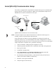

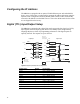
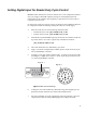


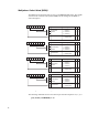

Table Of Contents
- Contents
- Introduction
- Assumptions
- Getting Technical Assistance
- Antenna Installation
- Reader Mechanical Installation
- RS-485/Ethernet Communication Selection
- RS-485 Impedance Matching Selection
- Serial (RS-232) Communication Setup
- Ethernet LAN Communication Setup
- Installing the RF Command Suite Application
- Configuring the IP Address
- Digital (TTL) Input/Output Setup
- Setting Digital Input for Reader Duty Cycle Control
- Transmit Power Calibration
- Transmitter and Antenna Configuration
- Manual Field Power Calibration - FCC Readers
- Manual Field Power Calibration - ETSI Readers

15
Setting Digital Input for Reader Duty Cycle Control
MP9320 readers with software version 1.33.04 or later can be configured for limited
duty cycle (trigger enabled RF output) by setting one of the digital inputs. This
functionality can be enabled to meet regulatory requirements or to set the reader to
respond to external events.
In order for the reader to recognize a trigger, the Protocol Control Word (PCW) must
be configured. Perform the following to setup the reader for external trigger:
1. Place the reader into one of the following automatic modes:
• Field Off between reads: }Cw,d:GCW,b:03,f:01!
• Field On between reads: }Cw,d:GCW,b:07,f:01!
2. Set PCW bit 13 (mask 0x2000). Typically, the PCW is set to 0x100 to enable the
tag activity buzzer. As a result, a typical setup command is as follows:
}Cw,d:PCW,b:2100,f:01!
3. The reader should now be in limited duty cycle mode.
4. Apply +5 to 24 Vdc to Digital Input Common pin 8 or 15 (D connector) or pin
“N” (round, MilSpec connector).
5. To trigger a read, apply 0 Vdc to digital input 1. As shown in the previous table
and in Figure 7, digital input 1 is pin “7” on the 15-pin D type connector or pin
“a” on the 26-pin MilSpec connector.
Figure 7–Main I/O Connector(s)
6. At this point, the reader should only radiate RF energy when digital input 1 is
pulled low (0 Vdc). Otherwise, the reader’s RF field shuts down.
7. For more information on reader configuration and control settings, refer to the
Comprehensive Heuristic Unified Messaging Protocol Reference Guide.
A
B
M
D
R
K
C
P
N
L
E
J
G
F
H
V
U
S
T
W
X
Y
Z
a
b
c
123
4
5
10
11121314
15
78
9
6
or
DigI/O-1
DigI/O-1