
Installation Guide


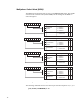

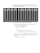

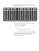
Table Of Contents
- Contents
- Introduction
- Assumptions
- Getting Technical Assistance
- Antenna Installation
- Reader Mechanical Installation
- RS-485/Ethernet Communication Selection
- RS-485 Impedance Matching Selection
- Serial (RS-232) Communication Setup
- Ethernet LAN Communication Setup
- Installing the RF Command Suite Application
- Configuring the IP Address
- Digital (TTL) Input/Output Setup
- Setting Digital Input for Reader Duty Cycle Control
- Transmit Power Calibration
- Transmitter and Antenna Configuration
- Manual Field Power Calibration - FCC Readers
- Manual Field Power Calibration - ETSI Readers

21
Antenna Transmit Power (TPx)
This register sets the antenna power for antenna ports 1, 2, 3,and 4 (TP0, TP1, TP2,
and TP3 respectively). Refer to the following sections for calculating the antenna
power index values.
Figure 11–TPx Bit Configuration
NOTE: The Power index values are obtained from the calibration tables listed in the
following sections.
Tx DAC Pwr
D0
Bit Name Function
D7
01234567
Tx DAC power setting
for the current antenna.
Bits 0-7.
RW
X
89101112131415
Bit Name Setting/Function
D8
D14
D15
High VSWR detected
RW
0 = Low VSWR
1 = High VSWR
X
Tx DAC Pwr
Tx DAC power setting
for the current antenna.
Bits 8-14.
X
1617181920212223
D16
Bit Name Function
D23
Reserved Reserved
RW
2425262728293031
Power index
Power index value from
calibration tables (see the
next section).
Bit Name Setting/Function
D24
D25
D31
RW
XX
Reserved Reserved