
Installation Guide

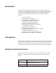
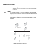

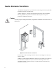
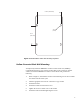
Table Of Contents
- Contents
- Introduction
- Assumptions
- Getting Technical Assistance
- Antenna Installation
- Reader Mechanical Installation
- RS-485/Ethernet Communication Selection
- RS-485 Impedance Matching Selection
- Serial (RS-232) Communication Setup
- Ethernet LAN Communication Setup
- Installing the RF Command Suite Application
- Configuring the IP Address
- Digital (TTL) Input/Output Setup
- Setting Digital Input for Reader Duty Cycle Control
- Transmit Power Calibration
- Transmitter and Antenna Configuration
- Manual Field Power Calibration - FCC Readers
- Manual Field Power Calibration - ETSI Readers

8
Reader Mechanical Installation
The MP9320 is designed for easy installation. The following instructions provide the
information to install your UHF reader.
As shown in Figure 2, the reader is designed for horizontal or vertical installation.
Mounting keyholes are provided on each side of the base plate for easy, non-
permanent, installation and removal.
Caution
To ensure proper cooling of the reader, verify that the fan intakes and vents are free of
obstructions.
Figure 2–MP9320 Reader Installations
For horizontal or table mounting, ensure the reader and all cabling is secured to the
surface or frame.
SAMSys recommends that the MP9320 be mounted on a horizontal surface. However,
if vertical surface installation is required, refer to the following sections for the
appropriate mounting. As shown in Figure 3, keyhole slots are provided for easy
installation and removal.
RS-232
Power
(15 Vdc 2.5 a
mp ma
x)
RS-485 & Digital I/O
MP9320 2.7 EP
C
UHF Long-Range R
eader
Fault
Power
Sense
Tra
nsmit
Active Antenna
12
3
4
RS-232
Power
(15 Vdc 2.5 am
p
max)
RS-485 & Digit
al I/O
MP9320
UHF Long-Ra
nge R
eader
Fault
Power
Sense
Tra
nsmit
Active
Antenna
1
2
3
4
RS-232
Power
(15 Vdc 2.5 amp
max)
RS-485 & Digital I/O
MP9320
UHF Long-Rang
e Reader
Fault
Power
Sense
Transmit
Active
Antenna
1
2
3
4