
Installation Manual


16
Field Power Calibration
The MP9320 can be operated with a variety of commercially available antennas and coaxial
cables. As a result, the output RF power of the reader must be configured to optimize the read
range for a given antenna configuration, while not violating FCC or CE regulations.
Calibration of the reader transmit RF power must only be performed by SAMSys authorized
installation personnel or certified resellers.
For readers with software version 1.3.1.pR1 or later, Field Power Calibration automatically
sets the MP9320 to the FCC or ETSI legal power limit. For FCC, power is adjusted to 1 Watt
maximum at the end of the coax cable or 4 Watt EIRP out of the antenna, whichever is less.
For ETSI, power is adjusted to 1/2 Watt ERP out of the antenna (800 mW EIRP).
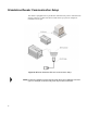
1. Build up system with cables and antennas in final configuration.
2. Disconnect antennas at the end of the cables. The unit compensates for cable
losses.
3. Set the unit to FCC or ETSI by setting the TPC configuration word as follows:
For FCC: TPC=10000, use the following CHUMP command:
}cw,d:TPC,b:10000,F:1!
For ETSI: TPC=0, use the following CHUMP command:
}cw,d:TPC,b:0,F:1!
4. Set each RF port configuration word (TPx, where x = 0, 1, 2, 3) for antenna gain
(dBi) and antenna polarization (linear or circular). If a port is not used, set g =
F HEX. Antenna polarization and gain settings are as follows:
Circular Antenna: TPx = 300g0000
Linear Antenna: TPx = 310g0000
where g = dB antenna gain in HEX (range = 0x0 - 0xf). Use gain in dBi for
linear polarized antennas and gain in dBic for circular polarized antennas.
5. For example, if you have the following configuration:
• 6 dBic circular antenna on port 1
• 10 dBi linear antenna on port 2
• Ports 3 and 4 not used
Use the following CHUMP commands to set each port:
}cw,d:TP0,b:30060000,F:1!
}cw,d:TP1,b:310A0000,F:1!
}cw,d:TP2,b:300F0000,F:1!
}cw,d:TP3,b:300F0000,F:1!